Here lies the documentation for my final project for HTMAA:
The Cricket Vending Machine. This is a machine that allows you
to eat crickets whenever you want. The video provides the most
complete process description of what I did.
I came up with my idea for my final project the very first day
of class and, as of writing October 16th, about 1.5 months
later, I'm still very set on this idea. As such, here I
document my progress on the final project.
Update: December 21st, I followed through with my plan from
months ago and demoed my cricket machine yesterday!!
Duration
September 7th-December 20th, 2022
Skills Learned
How to make almost anything
Image Source
Midjourney: An engineer standing at the end of a long tunnel
that represents the end of a long journey
01
Ideation (September 7th-October 16th)
A protein vending machine
The idea for a cricket vending machine came during class. I
detail more of the story in my week 0 documentation.
Esentially, I get hungry at night... very very hungry at
night. I want a reliable, automatic animal protein source at
any time. Crickets are uniquely positioned in that they are a)
animal protein, b) can reproduce quickly, which creates a
self-sustaining population, and c) it is not horrendously
inhumane to kill them.
Crickets? Yuck!
Understandably, most people are slightly grossed out at the
thought of crickets. This is very fair as I myself am afraid
of crickets. Also, crickets don't taste particularly good.
They are mediocre at best. Nevertheless, they are a
self-replenishing protein source!!
02
Design Planning
Narrowed scope
As stated in week 0, my cricket trough had the following
requirements:
1. sustaining the crickets
2. breeding the crickets
3. collecting crickets for processing
4. cleaning/preparing the crickets
5. cooking the crickets
It'd be nearly impossible to try to tackle all of these at
once. As such, I'm going to focus primarily on the first two
requirements for now, and then add on the other requirements
later.
The only potential downside of this is that, if I don't think
through the entire design now, I may end up completing steps 1
and 2, but in a way that's not scalable to sets 3-5.
As such, I'll focus most of my efforts on 1 and 2, however,
I'll keep in mind that I have steps 3, 4, and 5 to implement.
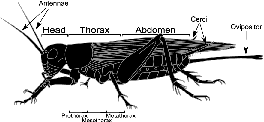
How Crickets Work
Cricket anatomy and stuff.
How Cricket Breeding Works
Essentially, there are three stages of environments that our
crickets must go through in their life cycle.
To start off, we receive a box of adult crickets from the
store. These crickets will be placed in a large container,
where they can eat, drink, and breed.
These adult crickets will live their lives, for about BLANK
days, before the females lay their eggs.
Here comes the second stage of cricket farming. Here, we
ensure that the female crickets lay their eggs in the correct
place. The females lay their eggs about 3/4" below the surface
of the topsoil. The eggs will then hatch after about 10
days.
Once the eggs have hatched, we move the crickets to the third
location, which is a kind of playground where juvenile
crickets can mature without being eaten by the adult crickets.
Materials Literature Review
I will go through the following resources to determine what
the moving parts are in a project like this.
1.
Video
tutorial on breeding crickets for hobbyists
2.
This
farm tour which gives a good overview of some of the processes
industrial-scale farms use.
3.
This
article gave me the most insight into how to actually sustain
and breed crickets.
4.
This
video details in-depth the process
In a much later section I will go more-indepth on a
component-by-component basis on what I need and how exactly
each of these components would work in my implementation.
Crickets
We actually need to, well, buy the crickets to start off our
colony! It's recommended to purchase 1,000 "quarter-inch"
crickets. These crickets are about 7-day old, and not quite
ready to breed yet. Crickets that are ready to breed are about
5/8" and 10-12 days old.
The reasoning behind younger crickets is that transport can be
very stressful for the crickets. If they are sexually active,
they may not adjust as quickly as younger crickets can. So
starting qwith 1/4" crickets is the move!
Primary Enclosure
Firstly, the crickets need some place to actually live their
adult life. The crickets live in a large container covered by
a screen protector
I also need
vermiculite
for the surface of the breeding container. The crickets don't
use vermiculite to burrow or anything, but rather, it controls
the odor for when the crickets defacate. It's very absorbent.
Rearing Chamber
The rearing chamber is a single chamber with 3 different
purposes:
1. Egg laying
2. Egg incubation
3. Juvenile cricket playground
Egg Laying Chamber
In the rearing chamber, we need an egg-laying container for
the crickets to lay their eggs. This egg laying container is
basically a tub of topsoil separated from the primary the
enclosure. The crickets need a separate substrate to lay their
eggs in.
Topsoil
retains moistrue much better and is more dense than
vermiculite. The cricket eggs need to be in a humid
environment, and the top soil helps with that.
The other method is as follows (source):
In the video, they leave the topsoil egg laying chambers in
the primary enclosure uncovered. However, I think it makes
sense to use a sheet of screening over the topsoil to prevent
the crickets from burrowing and eating their own eggs.
The female crickets can still lay their eggs too because they
actulaly have a needle on their butt. They then stick it into
the dirt through the screen and inject their eggs.
Incubation chamber
We leave the crickets to lay their eggs for about 1 week. The
idea is, you'll see more and more cricket eggs and at a
certain point they'll just stop laying eggs. Note that
crickets lay their eggs deep into the top soil, so you wont
see their eggs on the surface, so you may have to search a bit
to find the eggs.
The incubation chamber doesn't need much other than just
making sure that a) the temperature stays around 90 degrees
temperature and b) the topsoil is very very moist to prevent
the eggs from drying out.
After about 1 week, 100s of crickets will start hatching
everyday.
Juvenile Playground
Once the eggs have hatched, the juvenile crickets must be kept
be apart from the adult crickets. This is for two reasons.
Firstly, the adult crickets may eat the young crickets if kept
together. Secondly, for our food production, we only want
adult crickets.
Food and Water
The crickets also need to eat. There are off the shelf cricket
feeds available. The one in the video is
this.
With my feeding trough, I can provide both the dry food, as
well as treats like oranges and carrots. Diverse food sources
increases yield of cricket farming. Something he also mentions
is a water source for the crickets. What most breeders use is
some type of tissue, and you spray the tissue with water
ocassionally.
Note: Something that crickets DO NOT need is still water.
Crickets will jump into the water and drown themselves.
However, to automate this water refill process, I think it'd
be best to have water drip onto a sponge every hour or so. I
will plan to follow
this
tutorial to make a water drip system.
Crickets need a temperature of 85-90 degrees Farhenheit. That
means a heat lamp is necessary
In addition, it'd be useful to have several auxiliary cliamte
indicators, like temperature, topsoil moisture, and
humidity.
Something truly amazing would be to have the heat lamp and
water drip all automated based on auxiliary indicators.
01
Component-by-component Material Selection
Here, I will go in-depth to all of the moving parts of this
project and EXACTLY what materials I need.
red highlight = something I'll
need to purchase blue highlight = something
I'll need to make
Water
One interesitng idea I have for the water trough system is to
use this instead:
https://www.youtube.com/watch?v=7VjmYPj6Kb0.
This doesn't require any electircla components and I think
would be far simpler for my purposes!
This
is the alternative, more complicated option for this
Spring Loaded Cricket Depoist
In
this youtube
video, the man shakes the cricket condo in order to release
some of the crickets.I propose that, in the enclosure, one of
the cricket condos has a spring attached to it. When the user
presses a button, it should shake the crickets down into some
other area. spring loaded system for getting crickets to kill
and eat
Cricket Condos
In
this youtube
video, they mention "cricket" condos. Rather than using egg
cartons, I can laser print cricket condos
Primary Condos
The primary enclosure is the physical space where the adult
crickets live. This does not include the objects like the
cricket condos contained within. The primary condos in
this
tutorial are 12 inches tall, 23 inches wide, and 16 inches
long. This is perfect for about 500 crickets.
Egg Laying Containers
It's important that we have as much space for egg laying
containers as possible. Crickets will stop laying eggs if they
notice that the boxes are full (of eggs), so get as much
square footage as possible.
Divider
The window spline has a diameter of 0.125"
(https://www.amazon.com/gp/product/B09T2KKDSR/ref=ppx_yo_dt_b_asin_title_o00_s00?ie=UTF8&th=1)
Substrate
I need to buy vermiculite and topsoil! I layer 2 inches of
vermiculite in my primary container.
03
How I built it
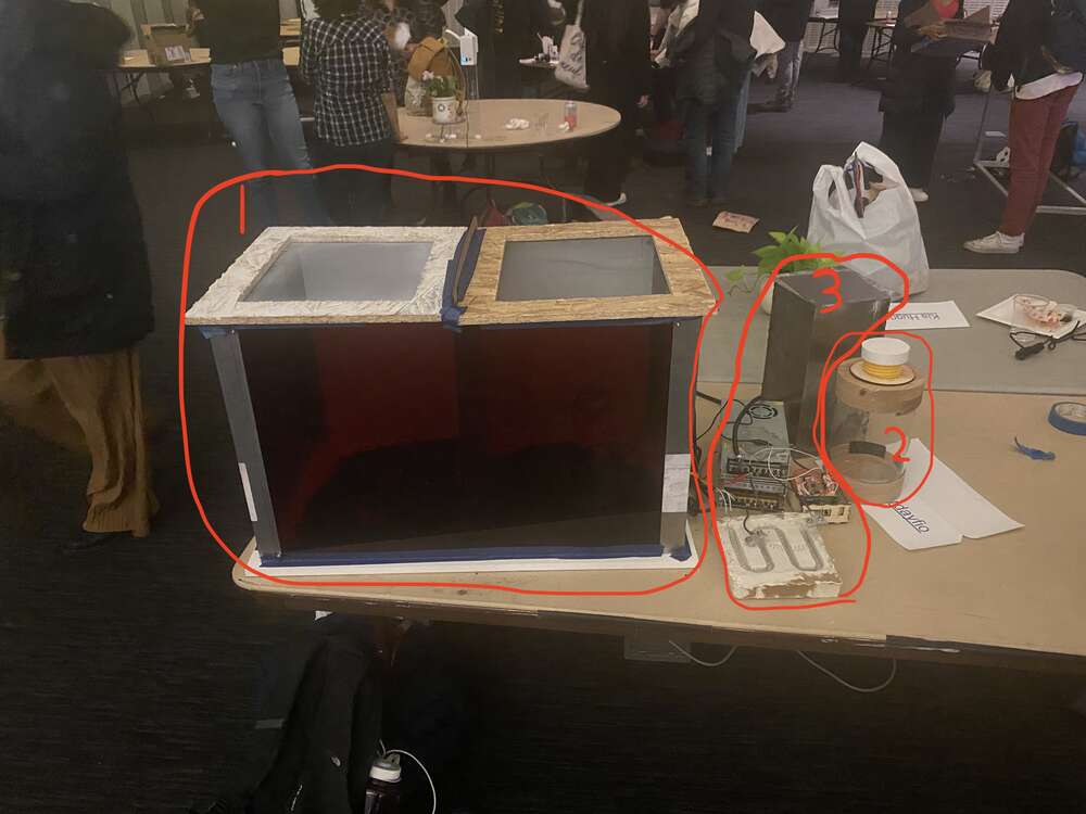
The below image shows each of the 3 major components of my
project. I will go into depth into how I built each one.
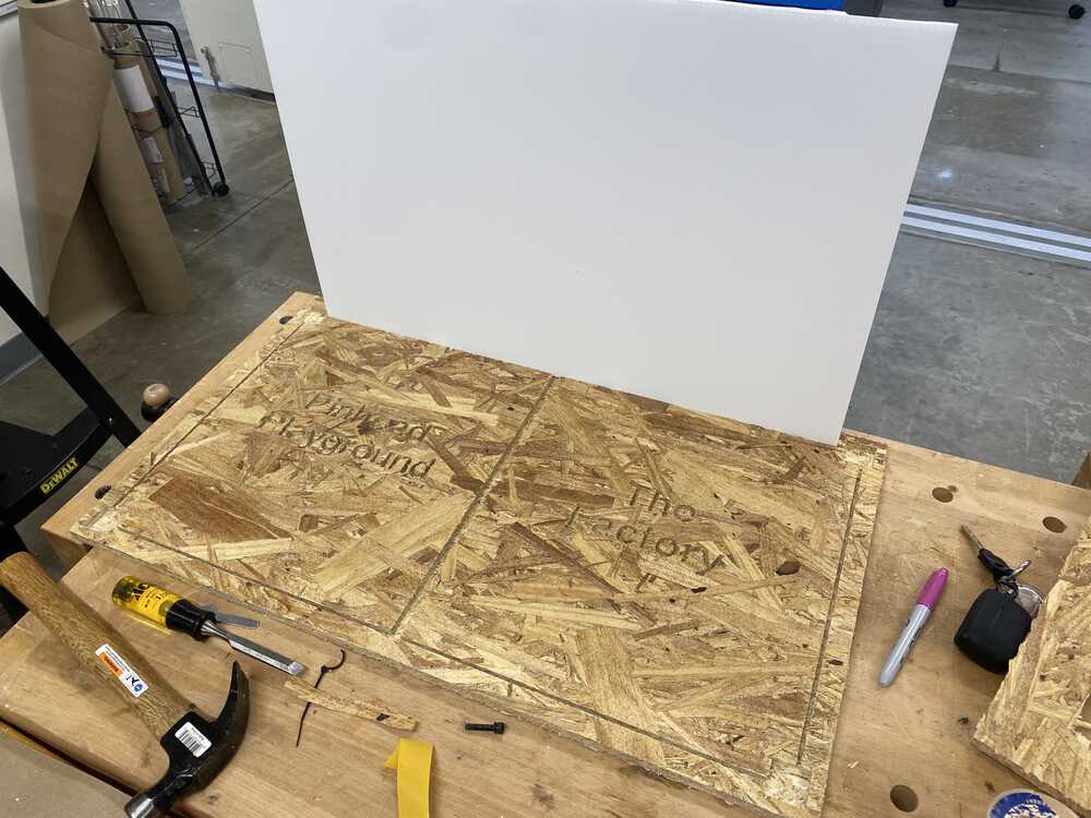
Component 1: The Cricket Grounds
The cricket grounds is the area where the adult crickets breed
and the pinheads play. It is quite large, at 70cm x 40cm x
50cm. The base of the enclosure is made of 1/2" synthetic,
plastic-like material. The sides are made of acrylic that was
laser cut to fit. Lastly, the ceiling is made of OSB. You can
read more about the prodcess of making this from the
computer-controlled machining week.
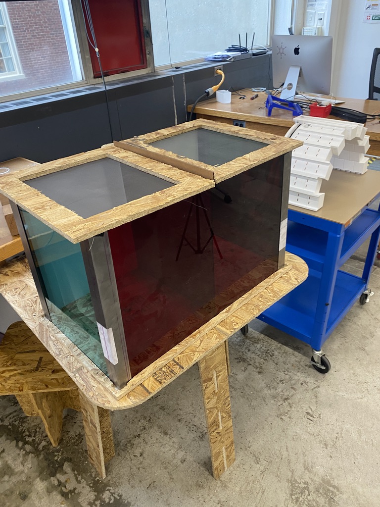
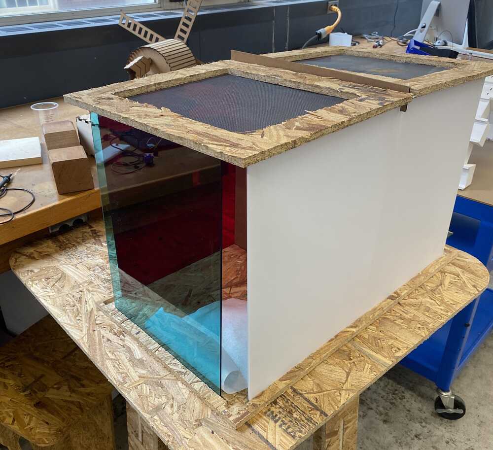
The enclosure
The enclosure made use of lots of subtractive manufacturing. I
used a ShopBot to mill the base of the floor and the cutouts
in the ceiling. I then used a laser cutter to cut the wall
panels as well as the cardboard backing.
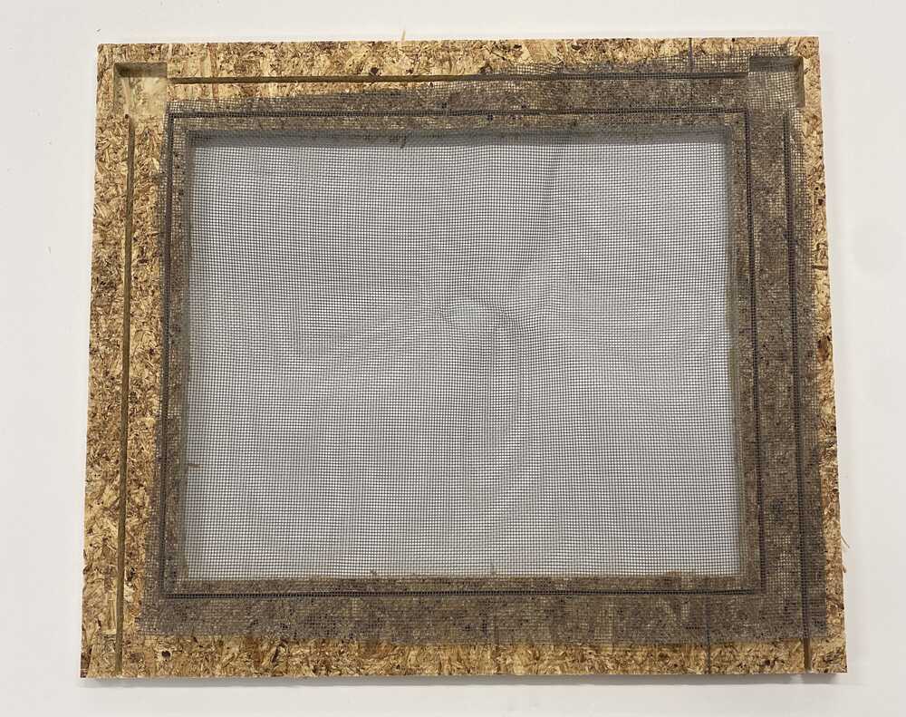
Ceiling
Adding the screens to the ceiling of the box. These
are necessary for allowing the crickets to breath,
while still preventing them from escaping.
Cardboard
The cardboard backing I used to form the back wall of
the container.
Progress Update 1
This was the first standing cage I had. The cage
stayed in this state for weeks before I finally filled
in the corners.
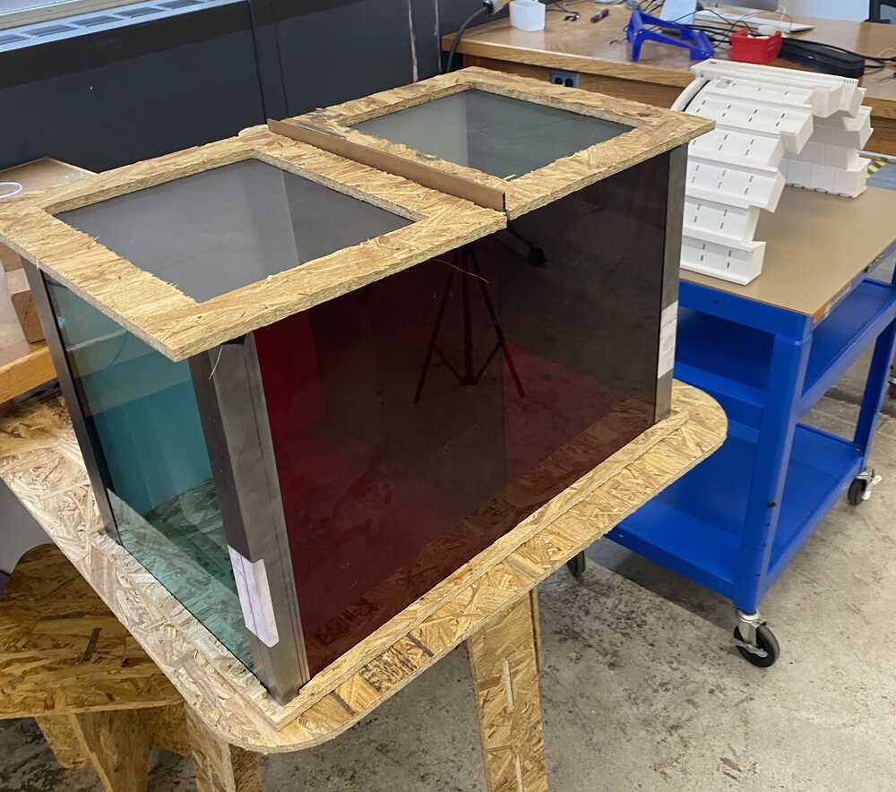
Progress Update 2
I filled the corners of the cage in with metal
brackets that I made. This decreased the places where
the crickets could escape by orders of magnitude.
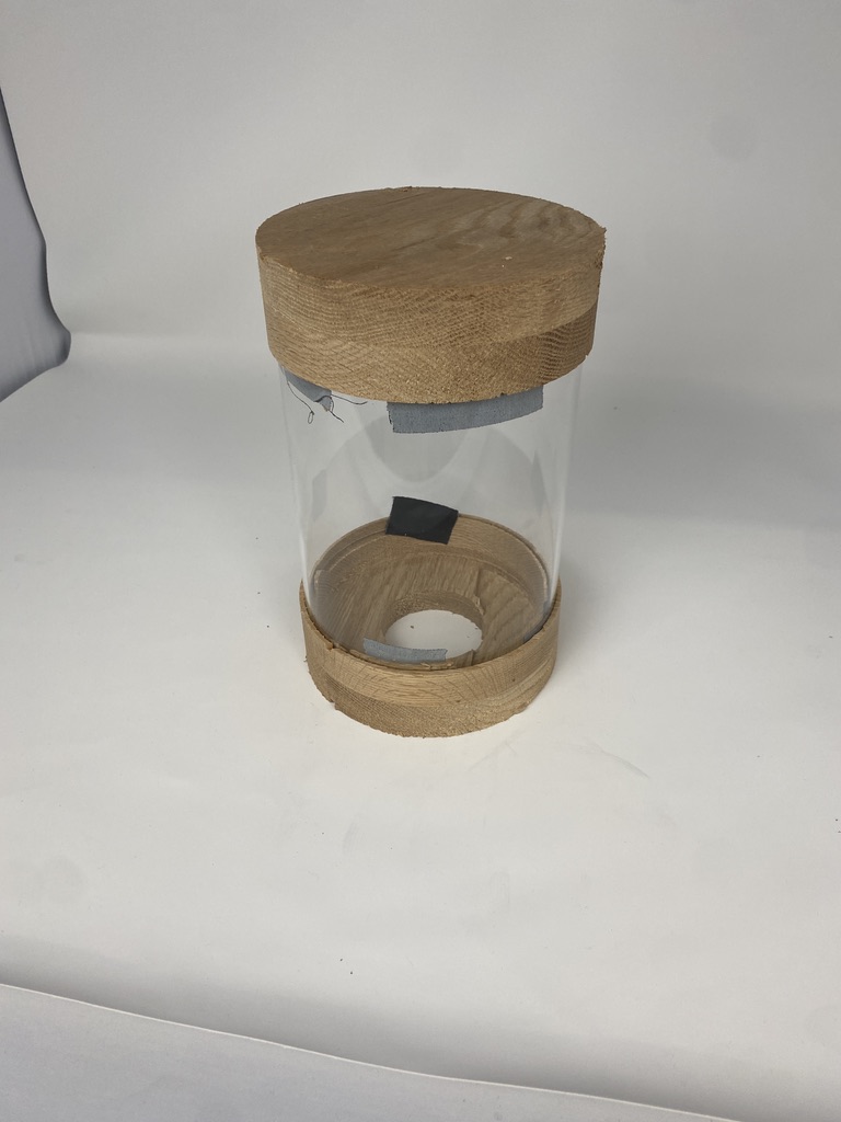
Component 2 is the cricket container. It is a capsule
container that holds the crickets. It's like a holding cell
for the crickets in-between going from the main container to
the oven. The way it works is the container is screwed onto
the main cage (from the back). When the user wants a cricket,
they unscrew the container and cover it with a piece of glass
(connected to the container itself). The user can then move
the container anywhere. For example, to humanely kill the
crickets, you can place them in a freezer first before putting
them in the oven.
The cricket container was one of the easier items to make and
was very milling intensive. I had to use the shopbot to mill
large quantities of thick wood.
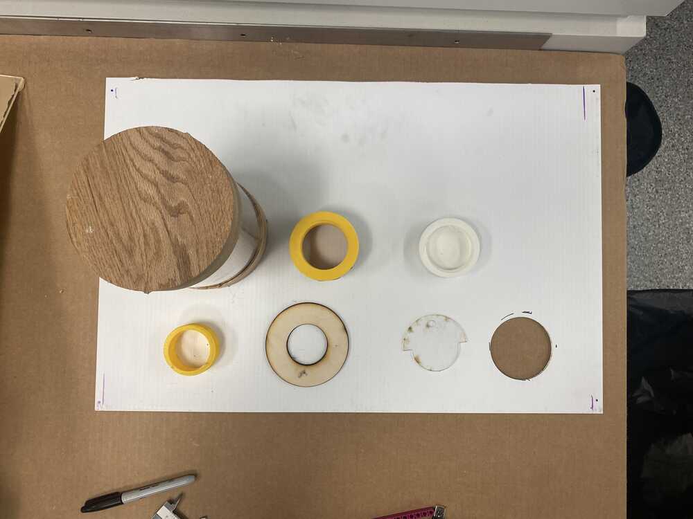
The container
Some of the different components that go into the container
system for the crickets
Component 3: The Oven
The final component to my device is the oven. The oven was the
device that was the most enjoyable to work on. When a user is
ready to cook their crickets, they place them in the oven,
turn the oven on using the adjustable control system and
display (bottom right of 3)!
The Heating Element
Creating the actual heating element for my oven was difficult
to say the least. I describe the full process in output week,
but essentially, I had to run current through a kanthal wire.
Having obtained a power supply and coiled wire during output
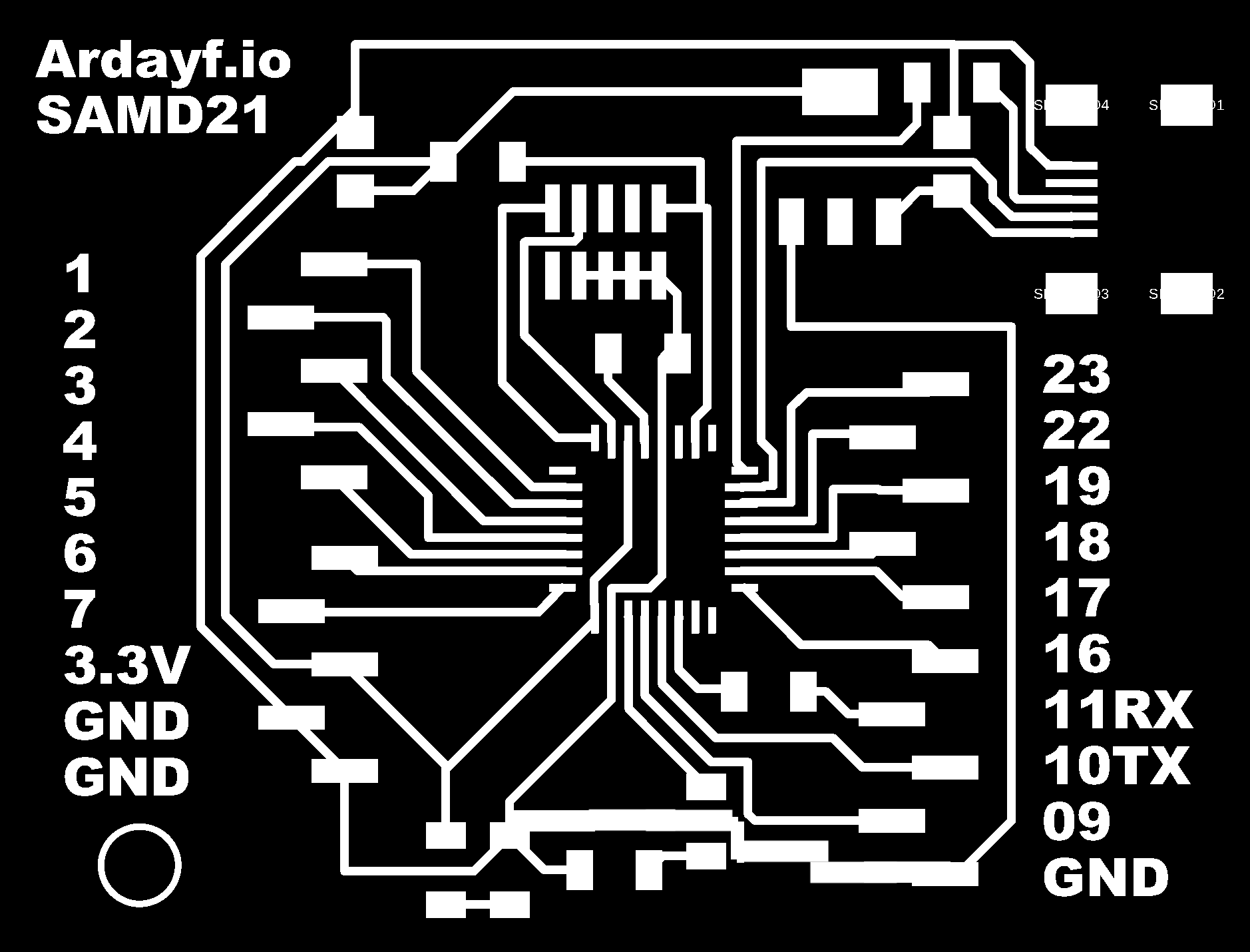
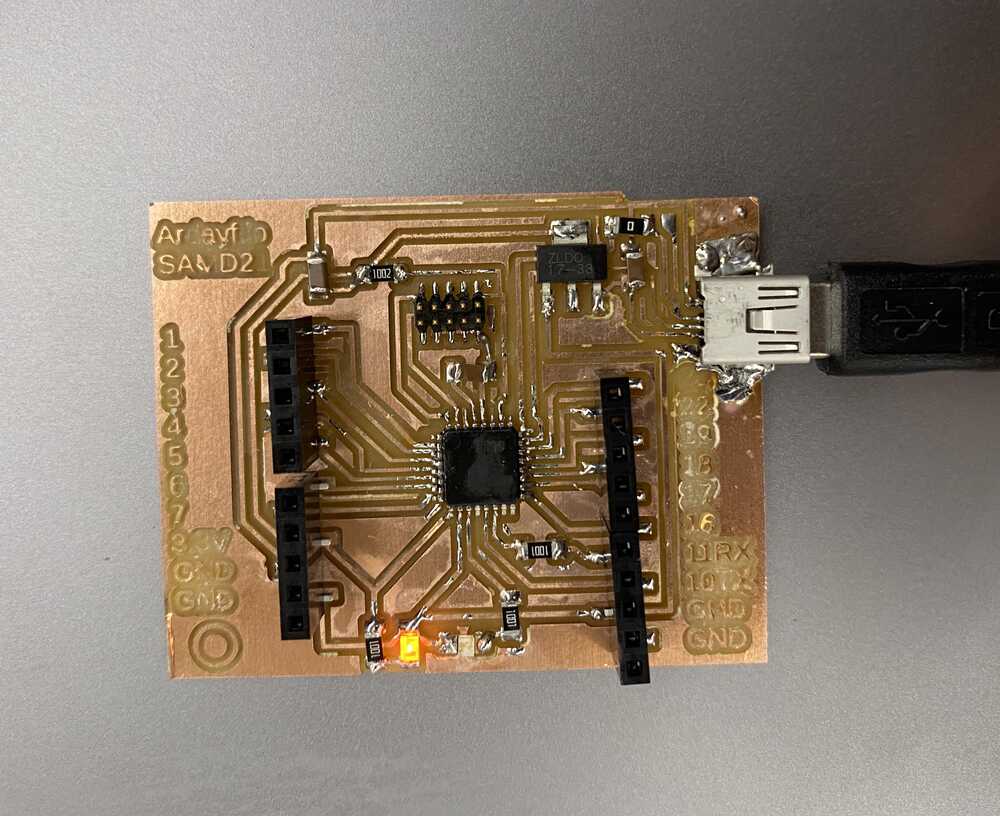
week, I needed to programatically control the oven. I designed
the following board:
The SAMD-21 devkit I designed to control the oven.
As stated in output week, I run current through the wire via
two large power supplies.
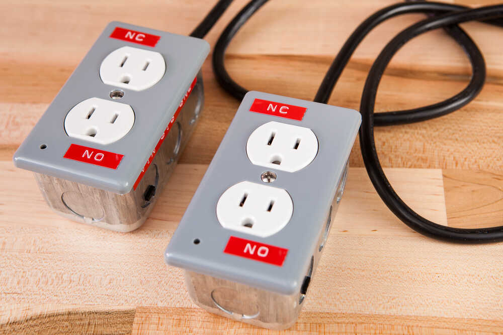
In order to actually turn the heating element on and off, I
needed to be able to control the power supply. I did this by
using large relay boxes I had found in the lab.
In order to toggle the state of the power supplies on or off,
I could toggle the voltage from one of SAMD digital pins! I
used alligator clips and I plugged the two terminals of the
relay into my ground and digital pin of my SAMD. The code that
could toggle the ovens on-and-off is as follows:
// constants won't change. They're used here to set pin numbers:
const int buttonPin = 2;     // the number of the pushbutton pin
const int ovenPin =  13;      // the number of the LED pin

// variables will change:
int buttonState = 0;         // variable for reading the pushbutton status

void setup() {
  // initialize the LED pin as an output:
  pinMode(ovenPin, OUTPUT);
  // initialize the pushbutton pin as an input:
  pinMode(buttonPin, INPUT);
}

void loop() {
// read the state of the pushbutton value:
buttonState = digitalRead(buttonPin);

  // check if the pushbutton is pressed. If it is, the buttonState is HIGH:
  if (buttonState == HIGH) {
    // turn LED on:
    digitalWrite(ovenPin, HIGH);
  } else {
    // turn LED off:
    digitalWrite(ovenPin, LOW);
  }
}
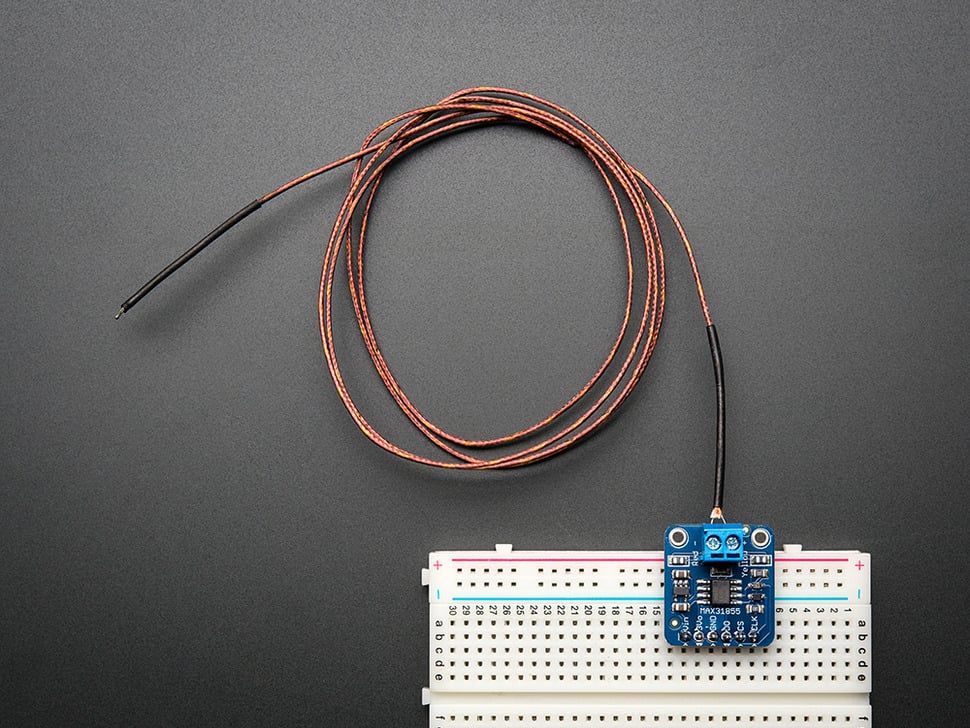
Detecting temperature
In order for the oven to have any value, it's necessary that
the temperature is recorded. I used one of Adafruit's
thermocouple's to detect the tempetrature.
Luckily, there is an adafruit library that makes programming
for the max6675 thermocouple easy. The code I used to detect
the temperature at a given time is the following:
#include "max6675.h" // max6675.h file is part of the library that you should download from Robojax.com

int soPin = 4;// SO=Serial Out
int csPin = 5;// CS = chip select CS pin
int sckPin = 6;// SCK = Serial Clock pin
MAX6675 thermocouple(sckPin, csPin, soPin);// create instance object of MAX6675
int vccpin = 3;
int gndpin = 2;

void setup() {


  Serial.begin(9600);// initialize serial monitor with 9600 baud
  Serial.println("MAX6675");
  pinMode(vccpin, OUTPUT); digitalWrite(vccpin, HIGH);
  pinMode(gndpin, OUTPUT); digitalWrite(gndpin, LOW);

}

void loop() {
  // basic readout test, just print the current temp
    Serial.print("C = ");
    Serial.println(thermocouple.readFahrenheit());
    //Serial.println(thermocouple.readError());
    delay(1000);
}
Interfacing with the user
While the oven could be turned on and off via a button press,
it was necessary to display to the user what the temperature
was. To do this, I used the OLED screen from networking week.
Some changes from networking week involve the fact that I want
an image of a cricket displyaed on the OLED at first, as I
think it'd be a cute first display. I used an image rasterizer
to convert a cricket I found online to a 128x64 pixel array
that could be used with the OLED. The link to the isolated
code for the display is
here.
Integrating the Code
I needed to integrate the thermocouple, button, and OLED code
all into one. This was actually, for the most part, just copy
and paste.
Here
is a link to the final code that I ran, I also include a
conceptual preview of some of the most important snippets of
code in the final build:
#include < Adafruit_BusIO_Register.h >
#include < Adafruit_I2CDevice.h >
#include < Adafruit_I2CRegister.h >
#include < Adafruit_SPIDevice.h >

#include < avr/dtostrf.h >
#include < SPI.h >
#include < Wire.h >
#include < Adafruit_GFX.h >
#include < Adafruit_SSD1306.h >
#include "max6675.h" // max6675.h file is part of the library that you should download from Robojax.com

int soPin = 4;// SO=Serial Out
int csPin = 5;// CS = chip select CS pin
int sckPin = 6;// SCK = Serial Clock pin
MAX6675 thermocouple(sckPin, csPin, soPin);// create instance object of MAX6675
int vccpin = 3;
int gndpin = 2;

int ovenPinOut = 1;
const int buttonPin = 2;     // the number of the pushbutton pin
int buttonState = 0;

#define SCREEN_WIDTH 128 // OLED display width, in pixels
#define SCREEN_HEIGHT 64 // OLED display height, in pixels

// Declaration for an SSD1306 display connected to I2C (SDA, SCL pins)
#define OLED_RESET     -1 // Reset pin # (or -1 if sharing Arduino reset pin)
Adafruit_SSD1306 display(SCREEN_WIDTH, SCREEN_HEIGHT, &Wire, OLED_RESET);

#define NUMFLAKES     10 // Number of snowflakes in the animation example

#define LOGO_HEIGHT   16
#define LOGO_WIDTH    16
static const unsigned char PROGMEM logo_bmp[] =
{ B00000000, B11000000,
  B00000001, B11000000,
  B00000001, B11000000,
  B00000011, B11100000,
  B11110011, B11100000,
  B11111110, B11111000,
  B01111110, B11111111,
  B00110011, B10011111,
  B00011111, B11111100,
  B00001101, B01110000,
  B00011011, B10100000,
  B00111111, B11100000,
  B00111111, B11110000,
  B01111100, B11110000,
  B01110000, B01110000,
  B00000000, B00110000 };

// 'cricket', 128x64px
const unsigned char cricket [] PROGMEM = {
// ..............................
};

void setup() {
  Serial.begin(115200);

  pinMode(ovenPinOut, OUTPUT);
  //digitalWrite(ovenPinOut, HIGH);
  //while(!Serial){}
  Serial.println("Beginning...");

  pinMode(buttonPin, INPUT);
  pinMode(vccpin, OUTPUT); digitalWrite(vccpin, HIGH);
  pinMode(gndpin, OUTPUT); digitalWrite(gndpin, LOW);

  // SSD1306_SWITCHCAPVCC = generate display voltage from 3.3V internally
  if(!display.begin(SSD1306_SWITCHCAPVCC, 0x3C)) {
    Serial.println(F("SSD1306 allocation failed"));
    for(;;); // Don't proceed, loop forever
  }

  // Show initial display buffer contents on the screen --
  // the library initializes this with an Adafruit splash screen.
  display.display();
  delay(2000); // Pause for 2 seconds

  // Clear the buffer
  display.clearDisplay();


  display.drawBitmap(0, 0, cricket, 128, 64, WHITE);
  display.display();
  delay(2000);
  testscrolltext("Chirp chirp...");
}

// serial print variable type
void types(String a) { Serial.println("it's a String"); }
void types(int a) { Serial.println("it's an int"); }
void types(char *a) { Serial.println("it's a char*"); }
void types(float a) { Serial.println("it's a float"); }
void types(bool a) { Serial.println("it's a bool"); }

void loop() {
  Serial.println("New iteration");
  //buttonState = digitalRead(buttonPin);

  // check if the pushbutton is pressed. If it is, the buttonState is HIGH:
  if (buttonState == HIGH) {
    // turn LED on:
    digitalWrite(ovenPinOut, HIGH);
  } else {
    // turn LED off:
    digitalWrite(ovenPinOut, LOW);
  }

  display.clearDisplay();
  display.setTextSize(2);
  display.setTextColor(WHITE);
  display.setCursor(30, 10);
  // Display static text

  float randNum = random(10000,99999)/100;
  char buffer[7];
  //dtostrf(randNum, 6, 3, buffer);
  dtostrf(thermocouple.readFahrenheit(), 6, 3, buffer);
  Serial.println(thermocouple.readFahrenheit());
  types(buffer);
  display.println("71F");

  display.display();
  delay(1000);
}

// ..............................
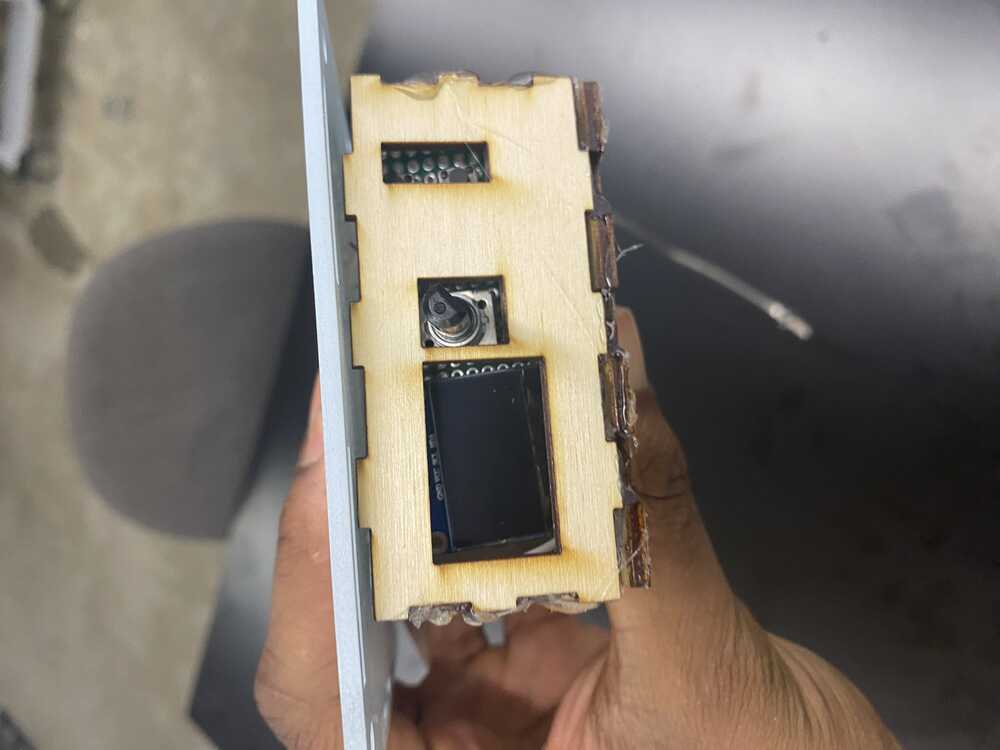
Circuit housing
I didn't want my circuit to be over exposed, so I designed and
laser cut a box to protect my circuit from the elements. The
box ended up being a bit underwhelming as I made the finger
joints a bit too small. This is a learning I will take into
next time!
The laser cut box to house my circuits.
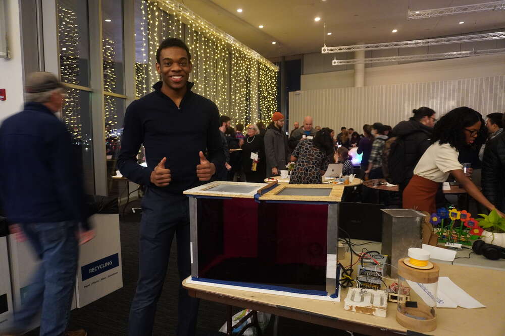
04
Recap + Future Goals
Photo credit to classmate Alexia Asgari
Recap
In this class, I really and truly learned how to make almost
aything. I'm surprised by the amount of work that went into
soething seemingly so simple. I used the diverse array of
digital fabrication tools I learned over the past semester to
create something taht I'm very proud of.
The Cricket Calculator
I intended on making a threaded module, whwere one could
simply the container (component 2) onto it and it'd calculate
the # of crickets + nutritional value associated with them.
Unfortunately, due to lack of time, I was not able toc omplete
this. Most of this time went towards the oven which, I
actually did not plan on making in the beginning.
Redesigning the Enclosure
During my demo, I noticed that the crickets were able to
escape. This forced me to apply ugly tape around the borders
of my cage. Not only is this unaesthetic, long-term, it won't
contain the crickets. I need to spend time reinforcing the
main dcontainer.
V3 On the Horizon?
I love building. It's my passion. As such, I plan on taking
this project to fruition. y current design is mediocre. I can
apply iterative improvements to make it better, but in the
end, it likely wouldn't be that amazing.