This week, I explored PCB fabrication.
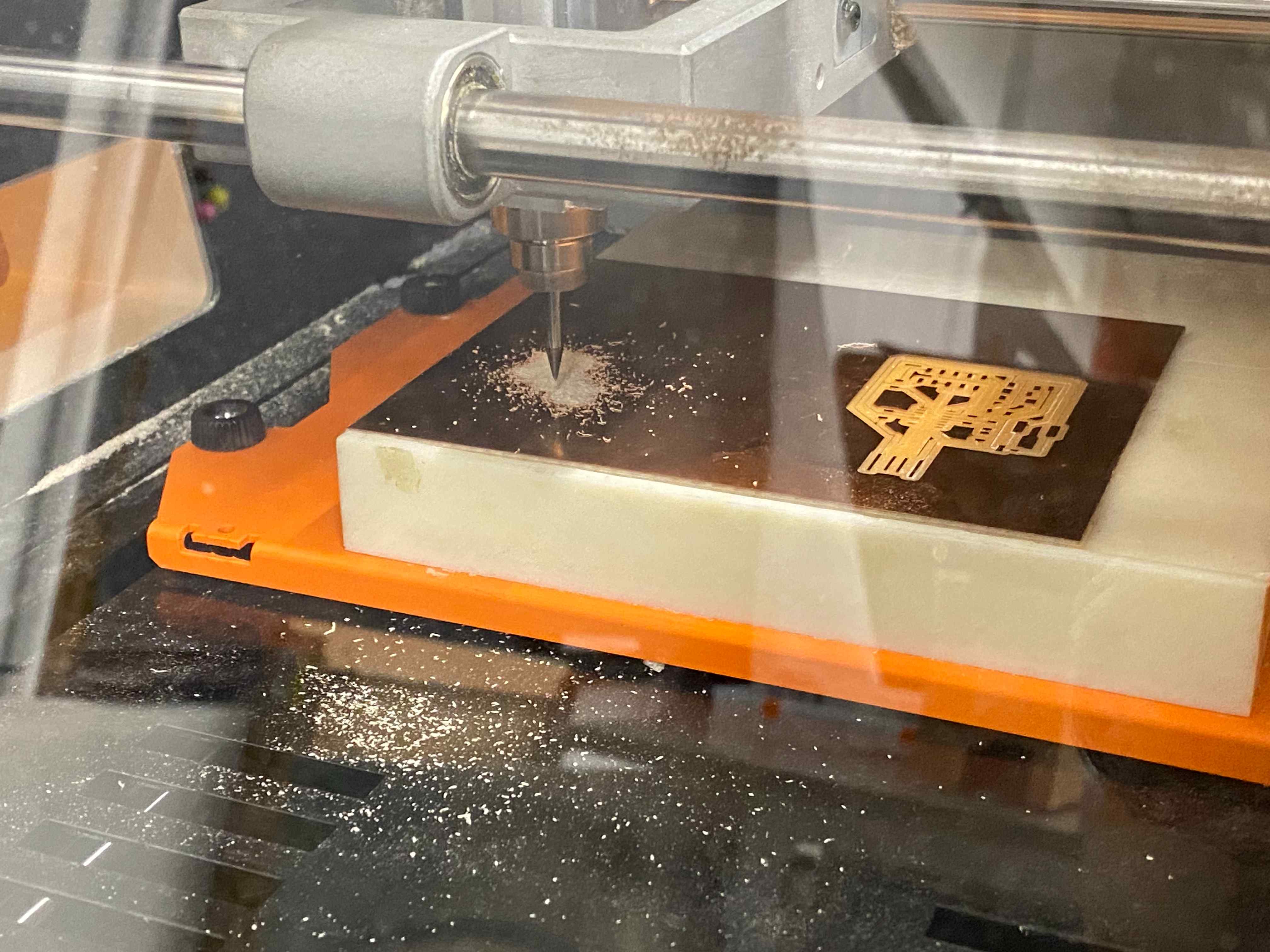
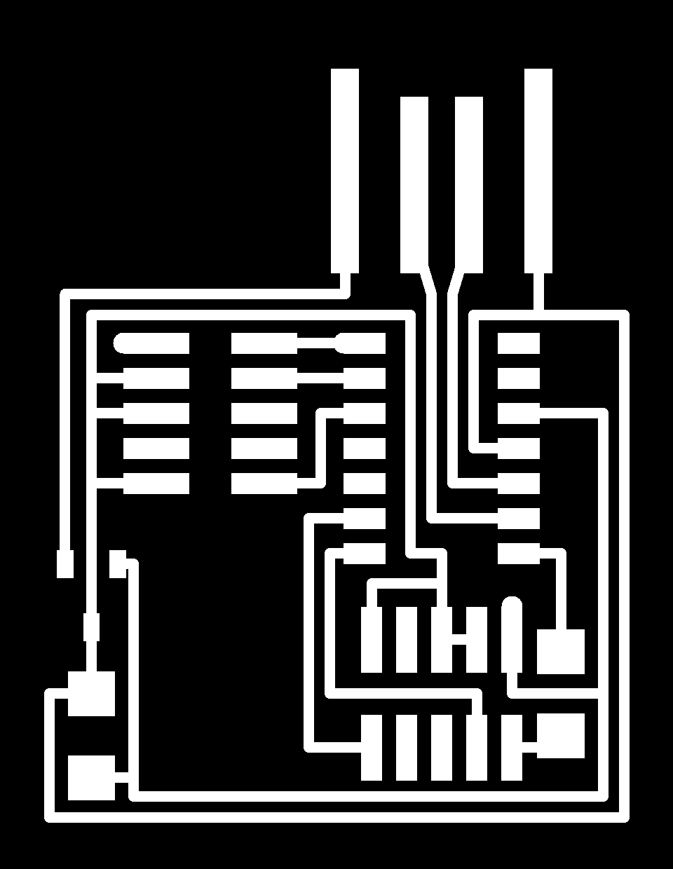
Using the Roland SRM20, I loaded the provided png images into mods and milled the board for the USB-D11C-SWD-10. During the first trial, the substrate was not taped well to the bed and moved as soon as the machine started. This was easily fixed with more double-sided tape.
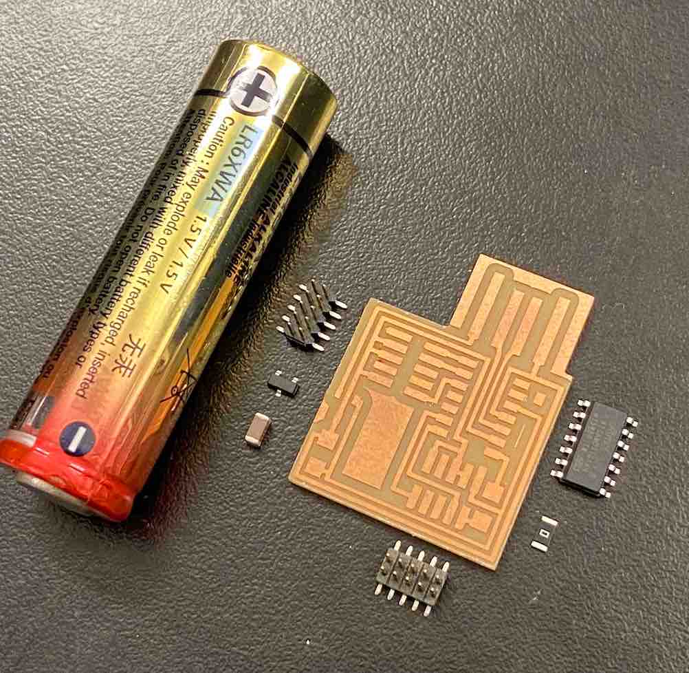
Hunting down the necessary components was slightly difficult, especially when they had abbreviated names like "IC2 3.3V." I eventually found them and soldered them the board, which was much smaller than anything I have previously soldered. Here is the board and components pictured next to an AA battery for size reference.
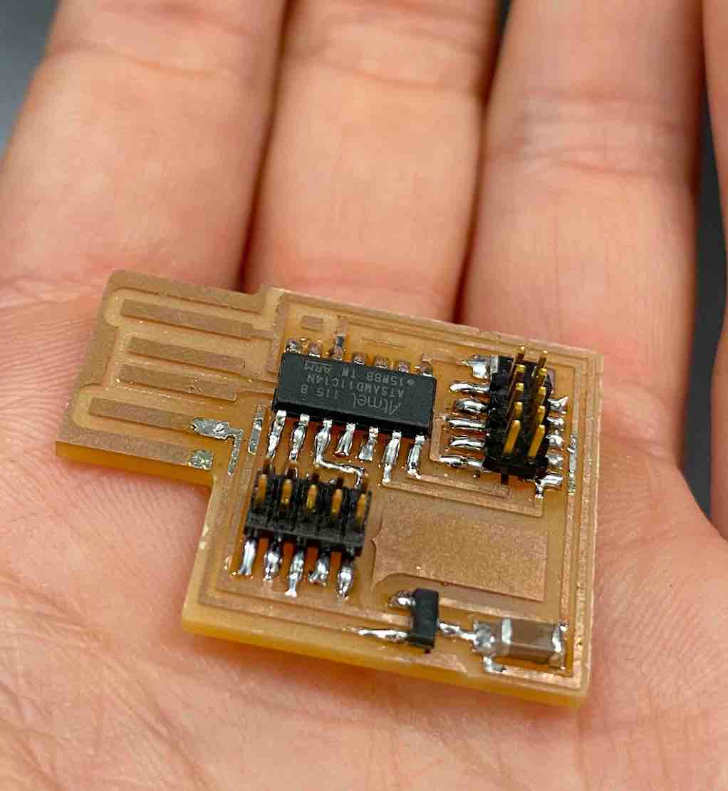
Upon checking with a multimeter, there were a few shorts, so I had to go back and re-solder some of the connections. I also aligned the microcontroller the wrong way at first, so I had to use a heat gun to remove it and re-solder a new one.
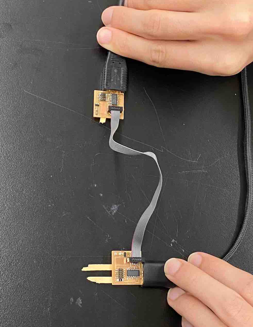
Cedric and Leo helped me program my board. First, plug in the bottom 5x2 header with orientation facing into the board (towards USB). The programmer needs to be connected to your computer. The board being programmed just needs a power source (which can also be the computer). Then, plug other end into a functioning programmer (if using USB-D11C-SWD-10, the header facing left). Download free-dap from Leo's website. Open terminal, navigate to the free_dap folder, then run "openocd." At first, the board did not register, but after many trials of adjusting the connection and plugging it in repeatedly, the bootloader and program were able to be loaded.
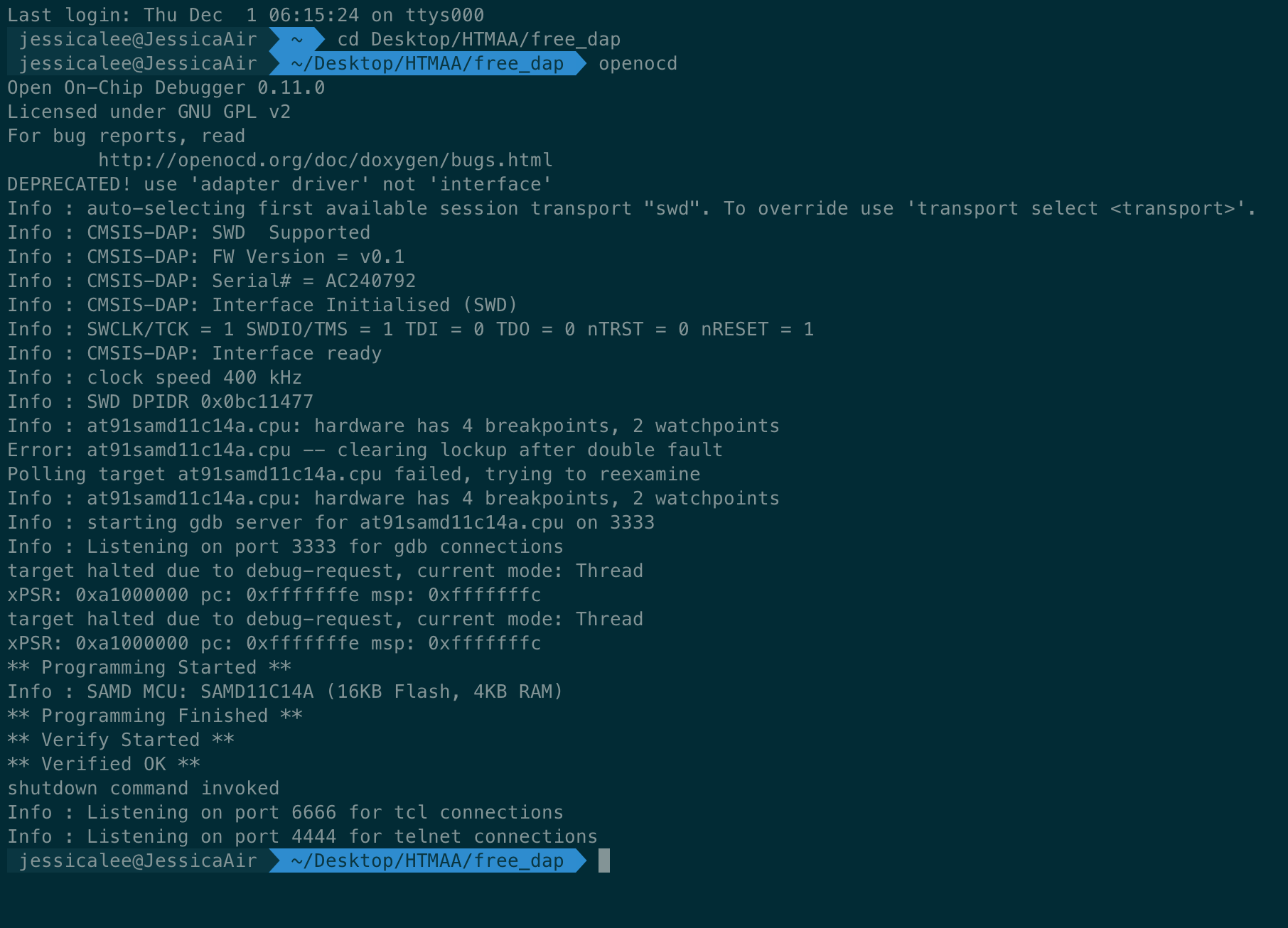 If sucessful, the above screenshot will be displayed.