Electronics Production
Utilizing the Roland SRM-20 I milled a PCB board design, stuffed it with the chosen components, and programmed it!
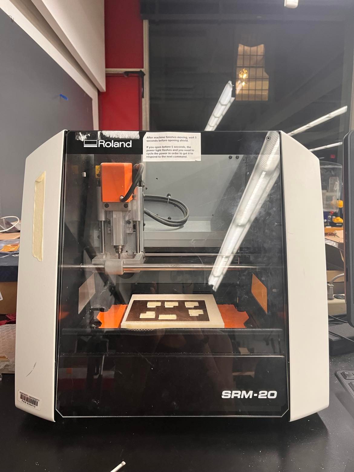
This week we were given the traces to mill a programmer on the Roland SRM-20. The file of the traces and the outline are below. At this stage, I wasn't sure what the traces indicated or how they translated to the parts that would be soldered onto the board. I leanred that the components we had to solder had footprints that were traced for ease of attatchment. So, I started with uploading the images to Mods and milling with the default settings.
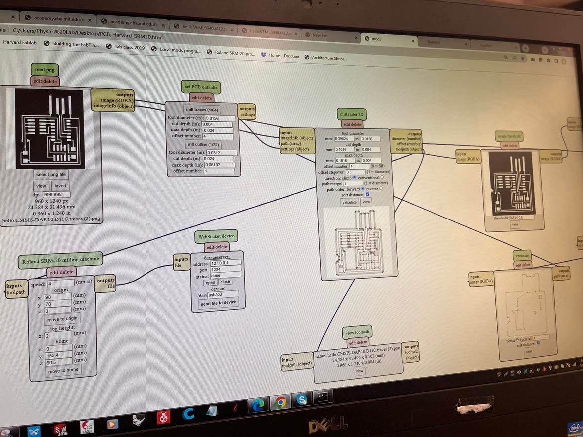
The setting for milling were preset, so I didn't have to worry about updating based on depth. To mill the traces we used a 1/64 bit and for the outline we used a 1/32 bit. To set up the CNC for milling the copper plate had to be stuck down with double-sided tape. I had a few milling mishaps which one was due to the plate not being level. But it was easy enough to fix and eventually I had a level bed to work off of.
There were some fails. I had the bits mixed up and the traces didn't cut the best for one, and also the late not being level resulted in very lightly milled traces which were unusable, but allowed me to become familar with the steps involved for set up. The proccess was straightforward. I homed the mill head, moved the bit almost all the way up, and then moved it to the set position which I adjusted. Then, I lowered the bit into position to cut and starting the cutting in mods.
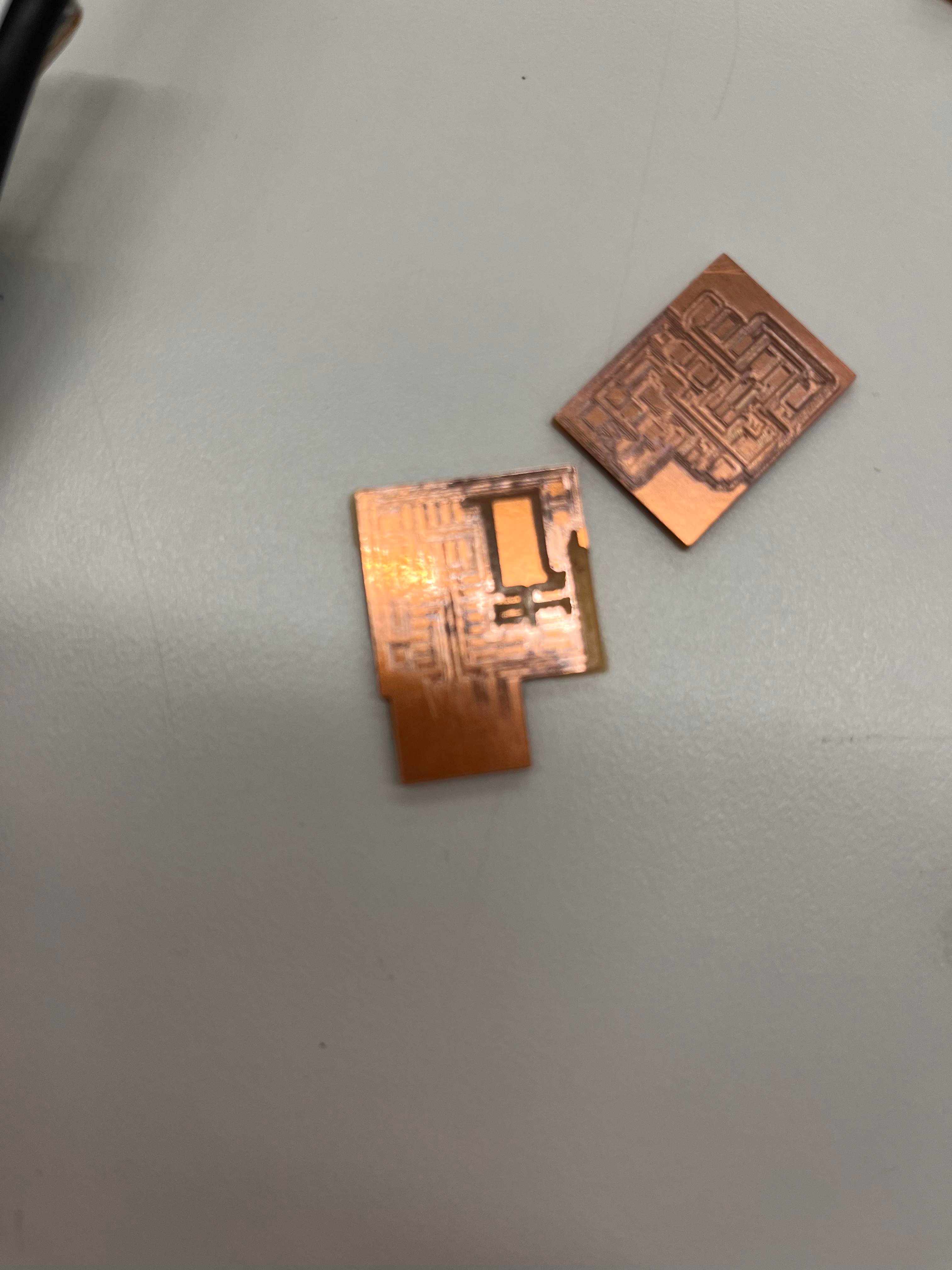
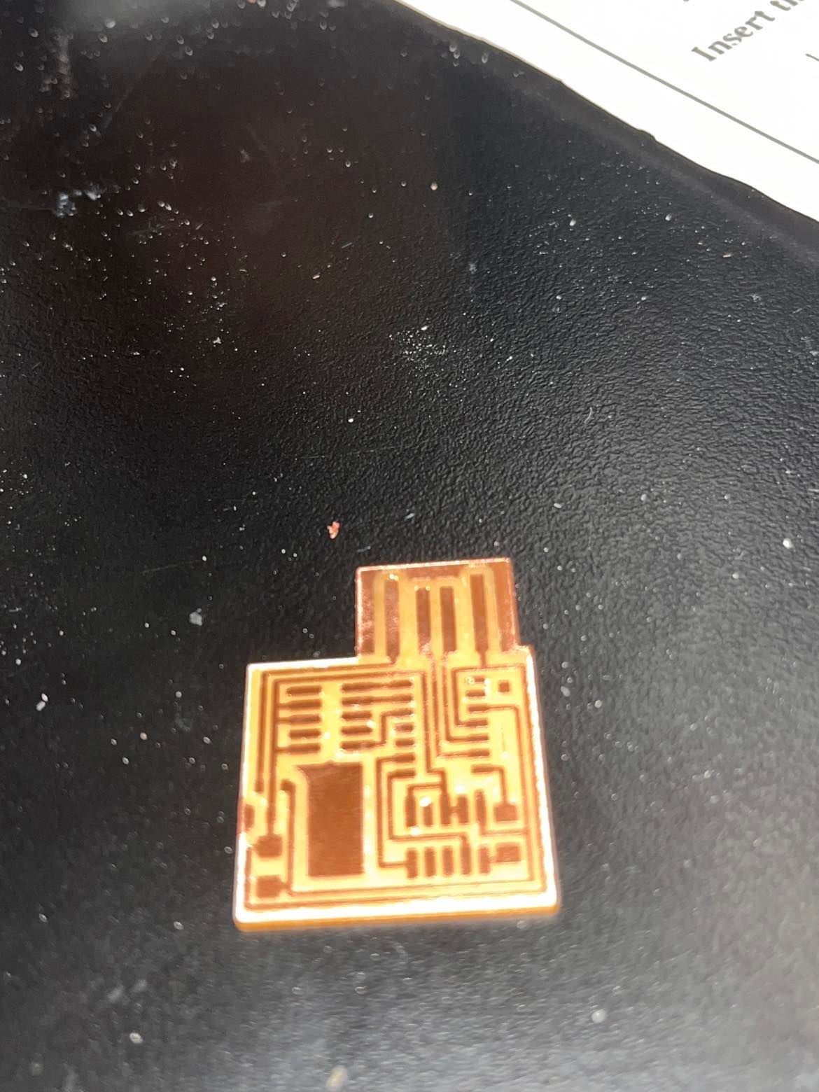
The third time was in fact the charm. I reattached the copper plate, made sure I had the correct bits, and it cut successfully.
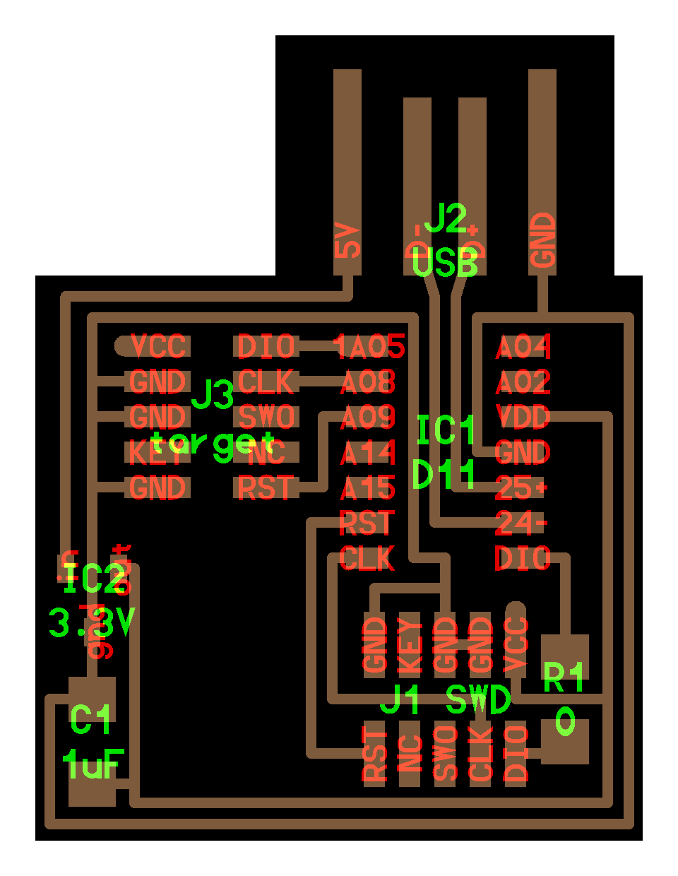
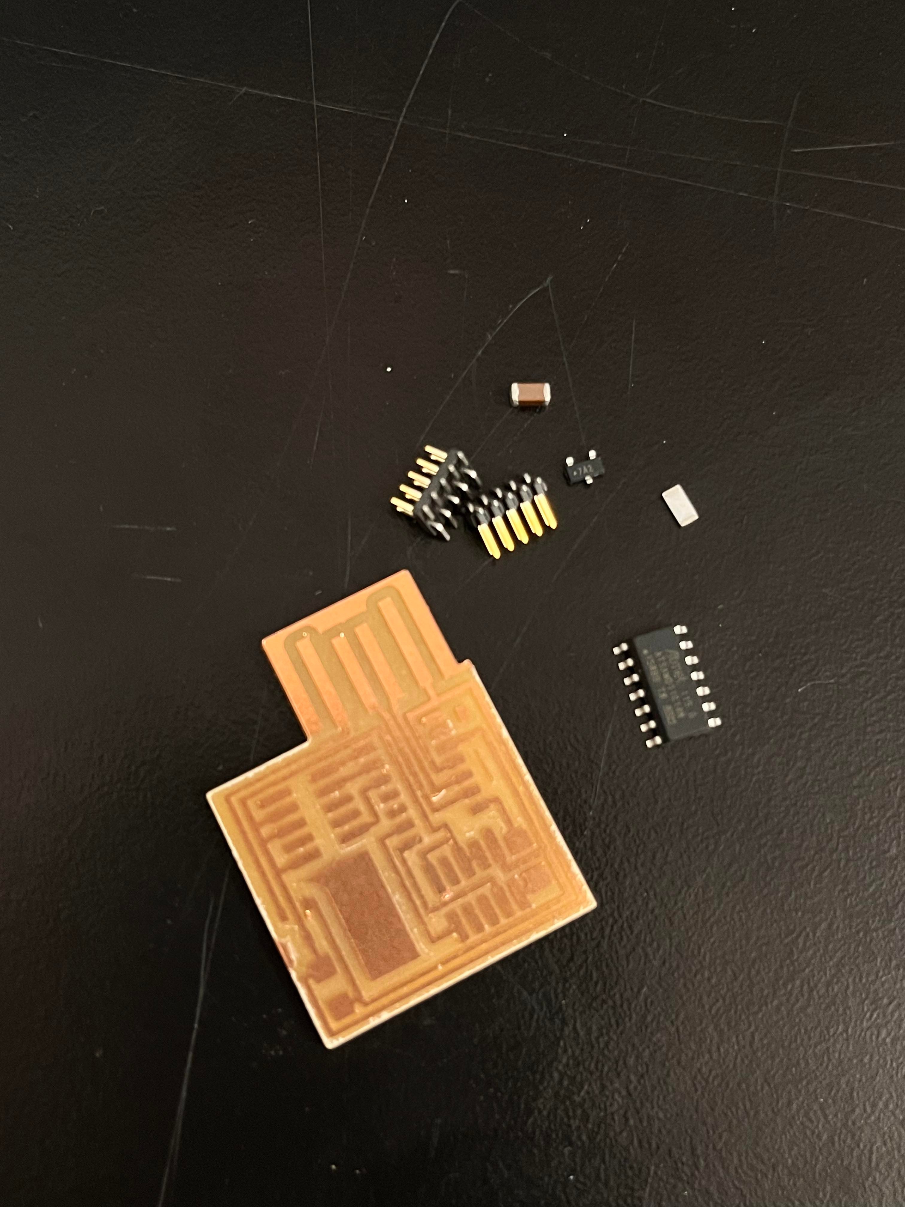
The next step was to stuff the board and I referenced the board design below. It was not clear which components translate to the
parts I needed to find at first. With the help of my lab mate, I was able to collect the voltage regulator = IC2, 1 uF capacitor = C1, a jump resistor R1, and two sets of pins for J3 & SWD.
I collected the components and then it was time to solder. I hadn't soldered pieces this small before, but the flux was helpful in getting the solder where it needed to go.
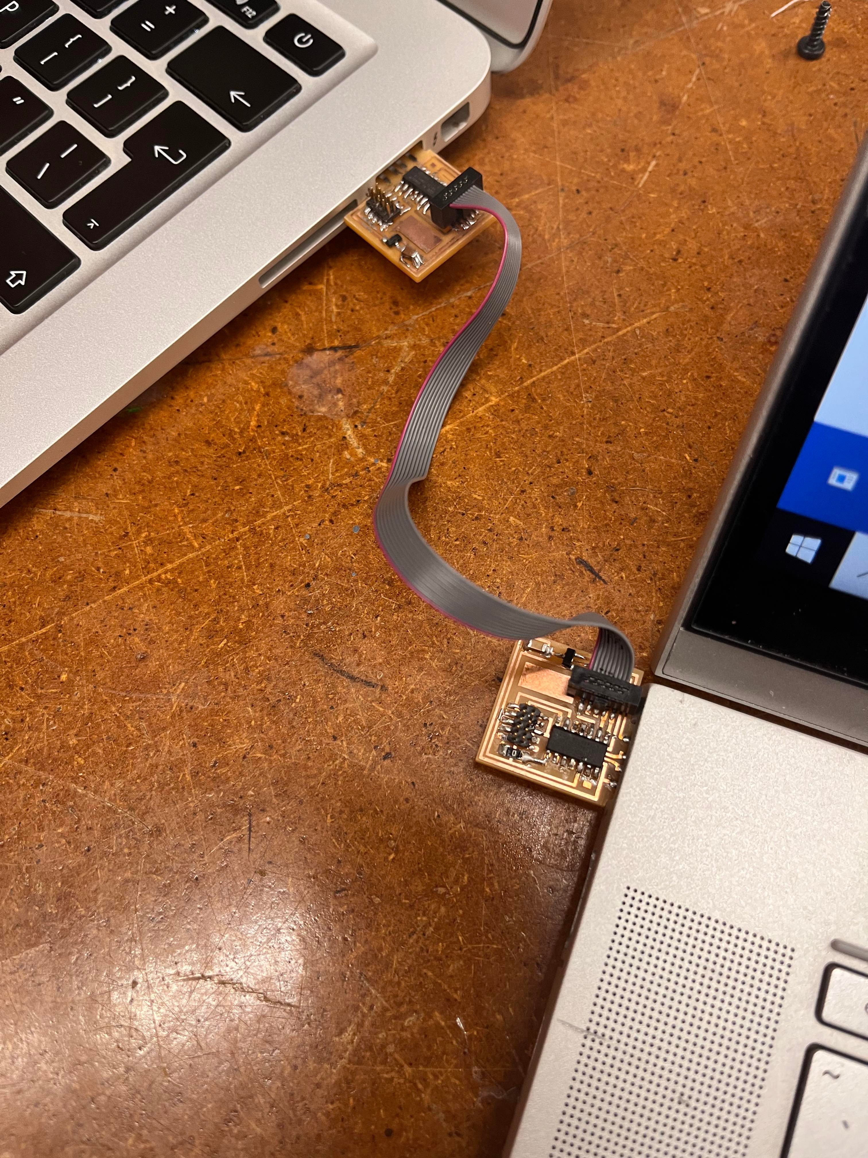
Successful soldering!
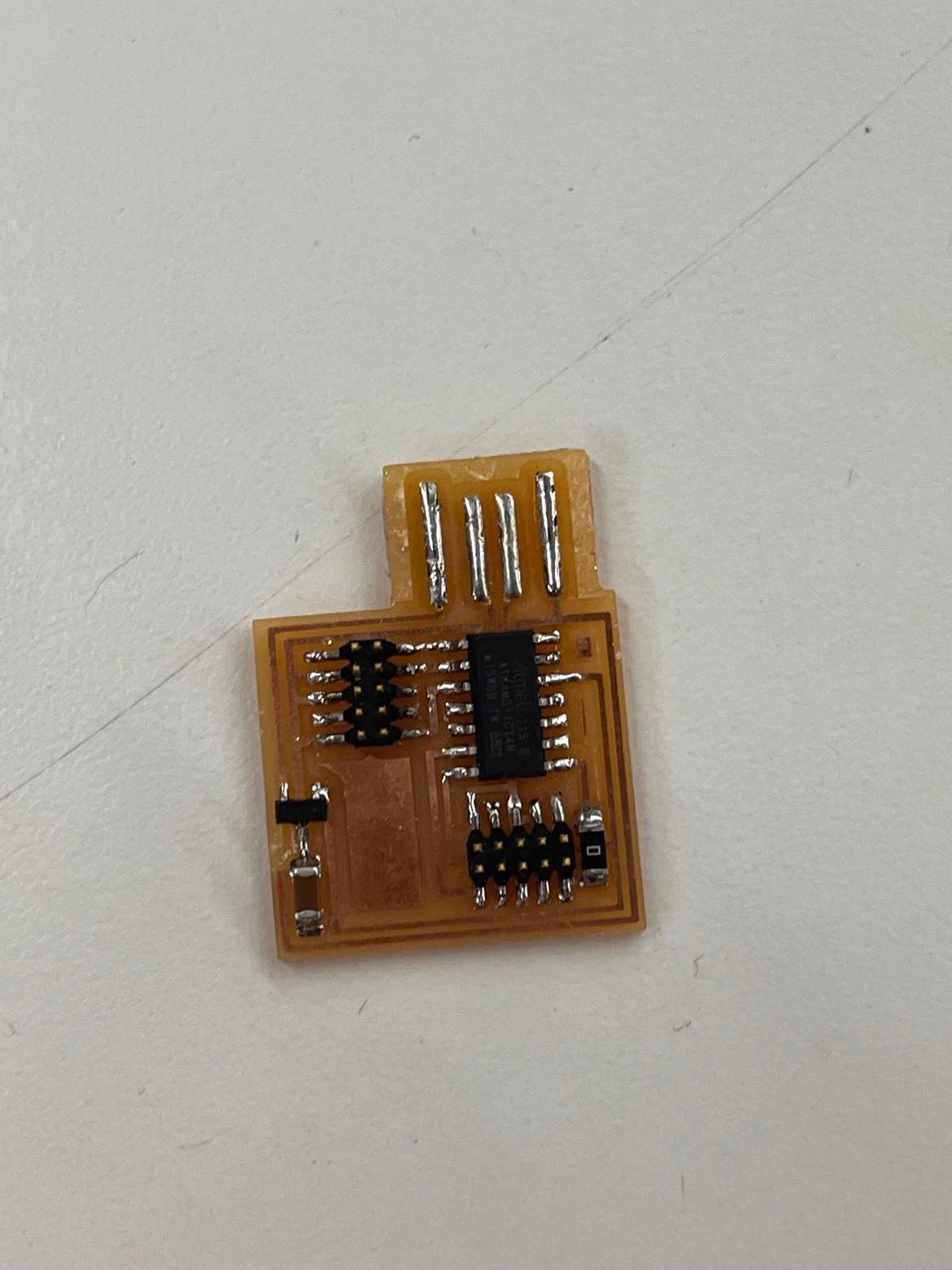
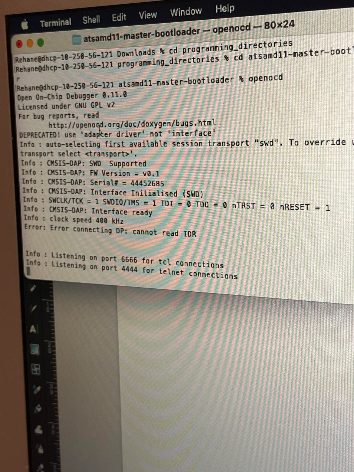
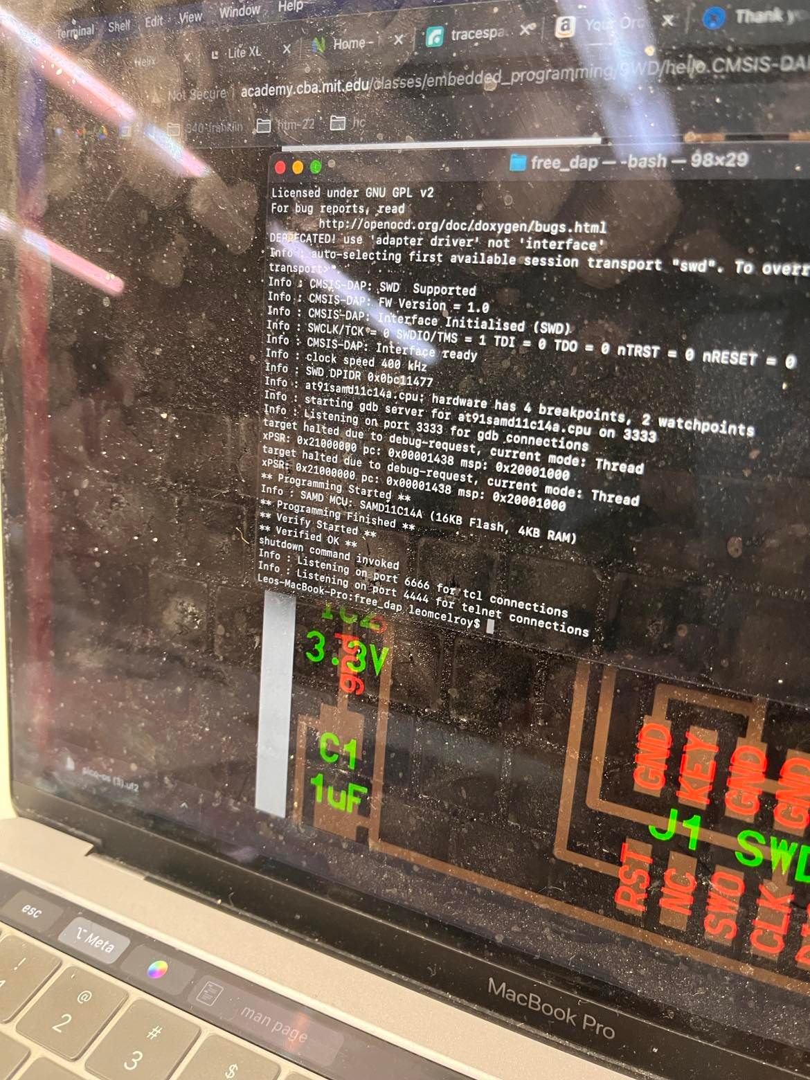
There were significant difficulties along the way. With soldering tiny components, I had a short and a missed connection to fix as my board could not be programmed. I spent a couple hours debugging with my lab mate and it didn't work. Later in the week, I had office hours with Leo and the board seemed okay but could not be programmed. It seemed like a very finicky proccess. MSYS2 & Gitbash were downloaded for programming, but I wasn't sure how to use these to bootload my device. I hope to understand more in the programming week.
1st & 2nd Programming Attempts Screenshots