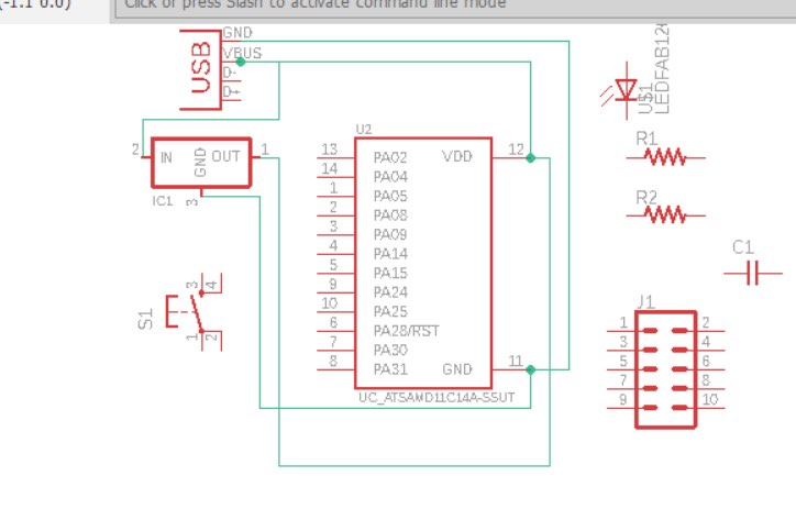
Wiring
I had trouble with getting good resolution, which was I was helped with by the TA on duty. At this point, I realized that I had the wrong 2x5 connector which will need to be removed and then updated before proceeding to milling.
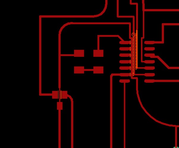
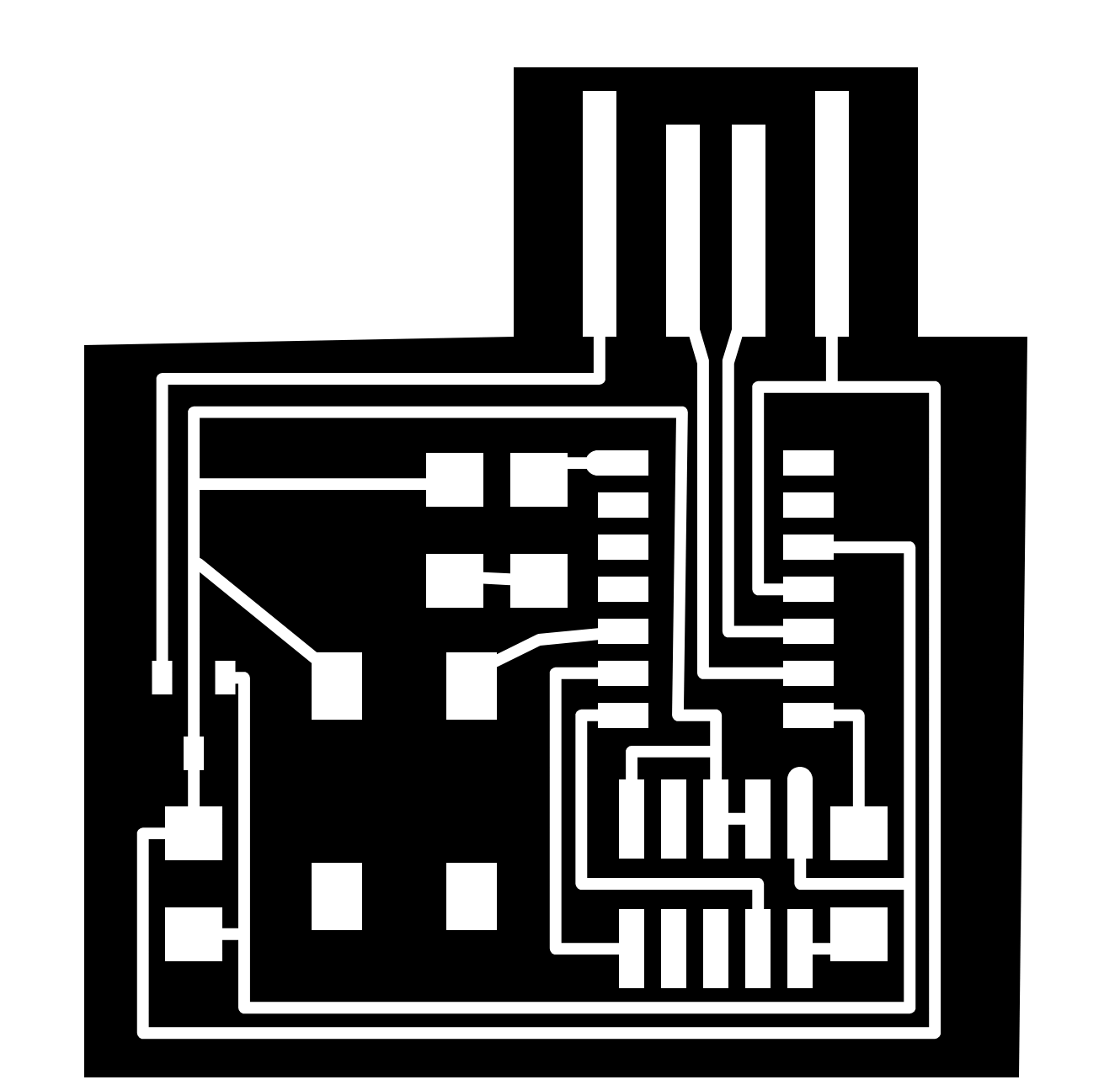
Traces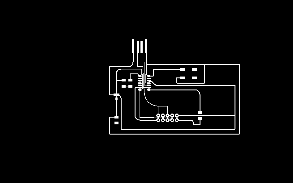
At this point I recieved help from Leo to get the board done. He reccomended that I use SVG-PCB to modify the D11 board to include a button and LED.
.PNG)
I added the component and thanks to the parametric design it was fairly easy to rearrange the board to include the button and add traces to integrate it with the board.
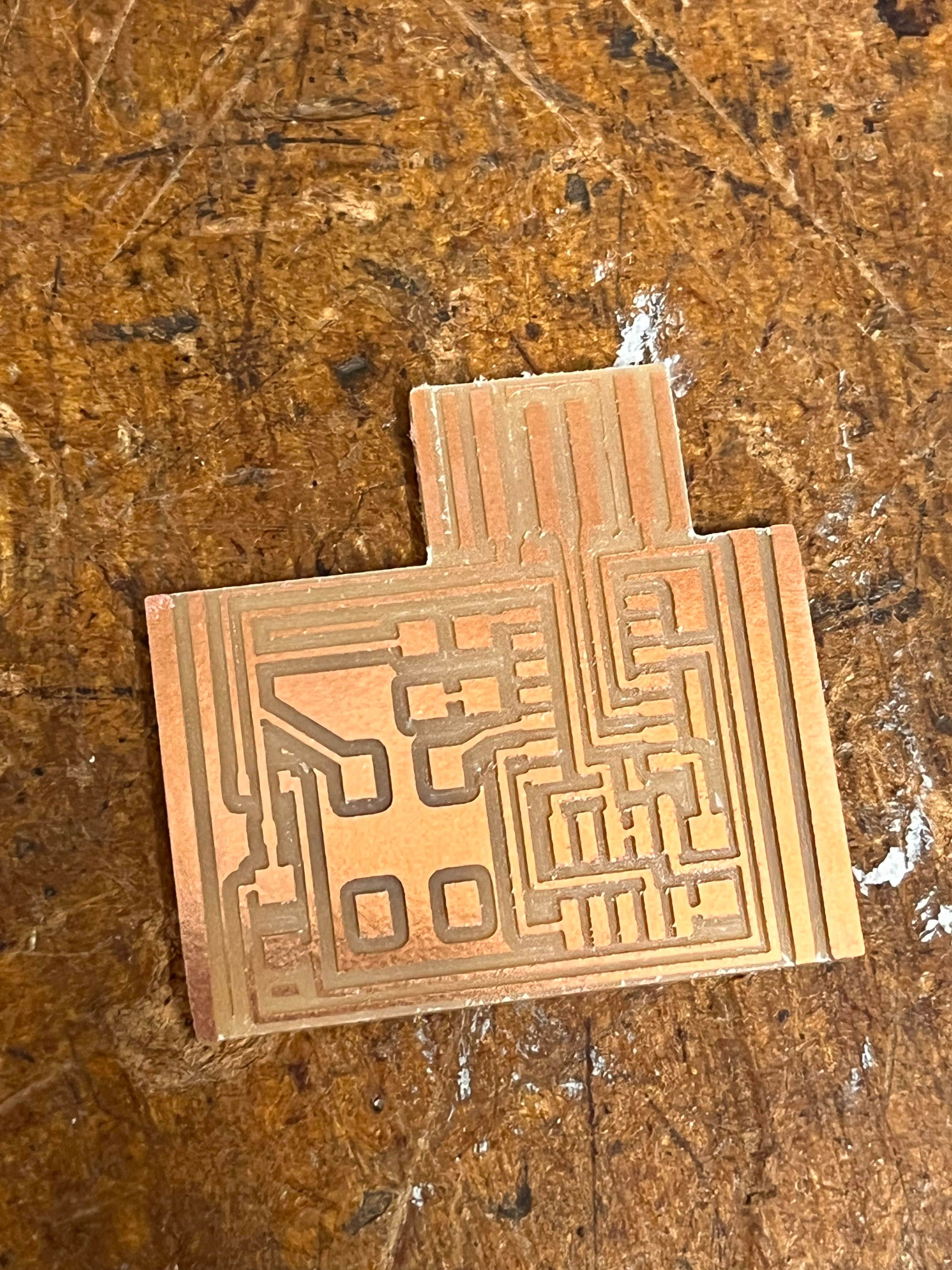
The next step was milling. I spent many hours struggling with getting the correct depth, replacing old bits, bed adhesion, and adjusting the settings with Leo's help.
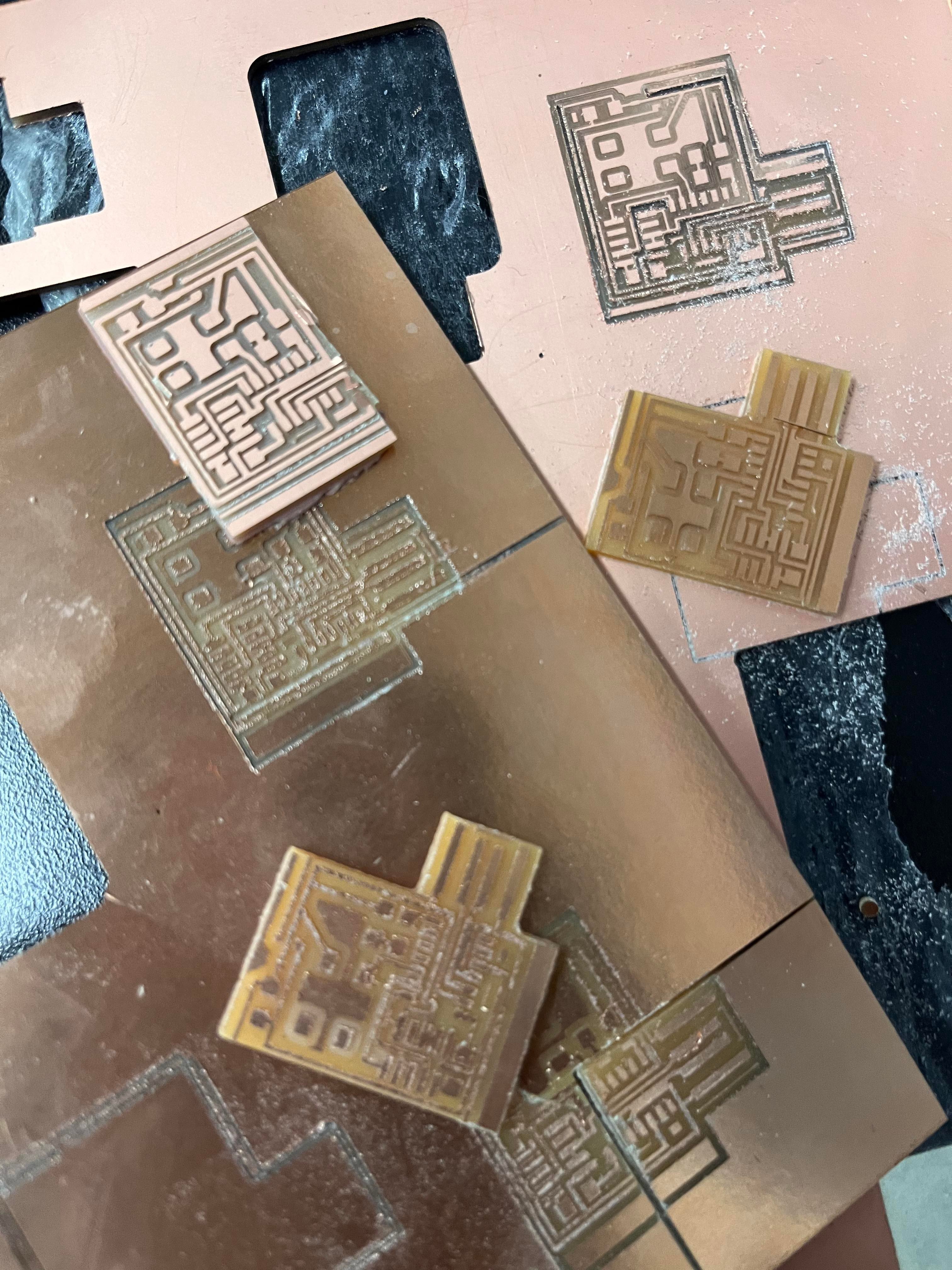
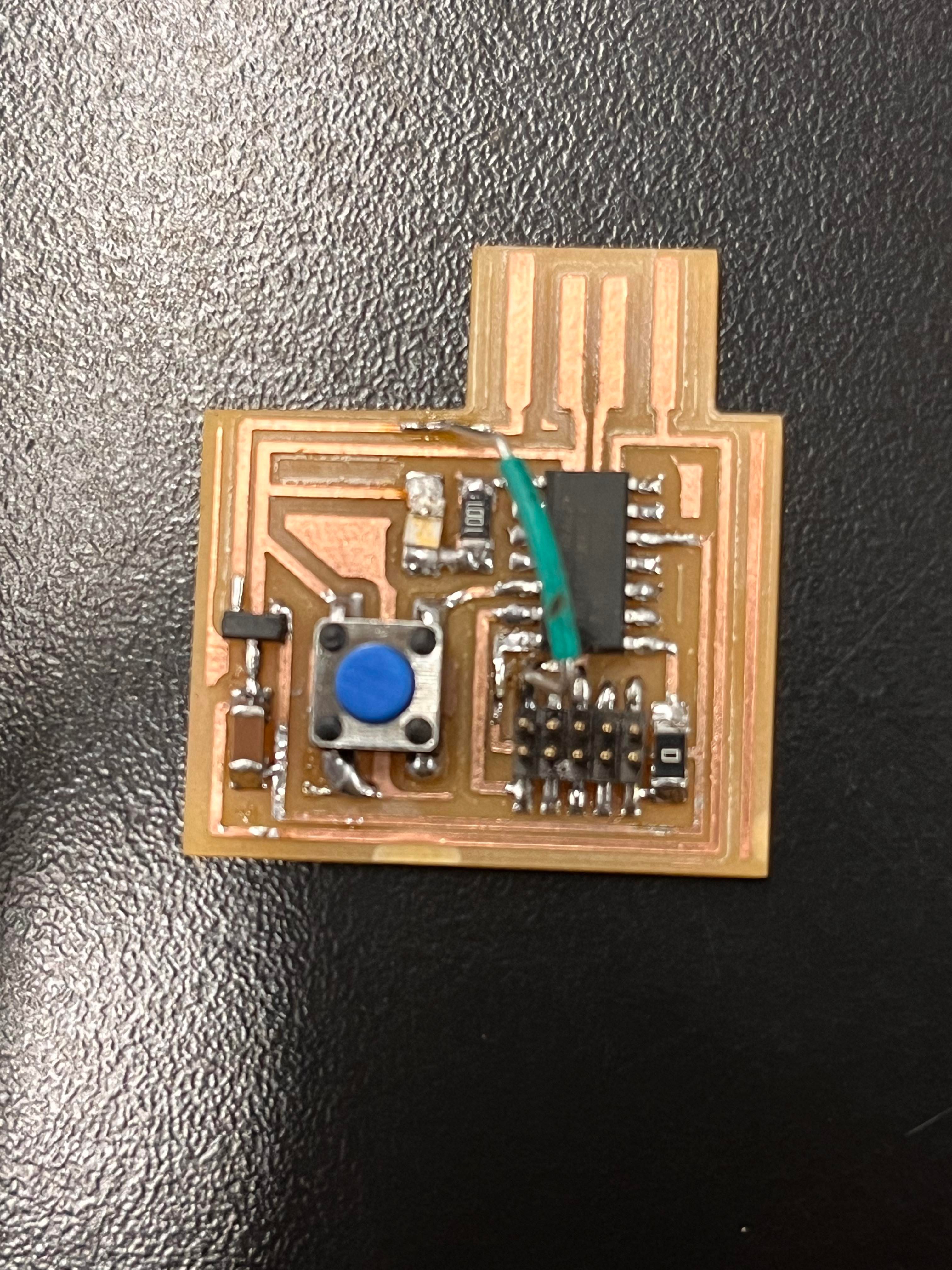
After a lot of persistence, I finally had a decent board to stuff with the neccessary components.
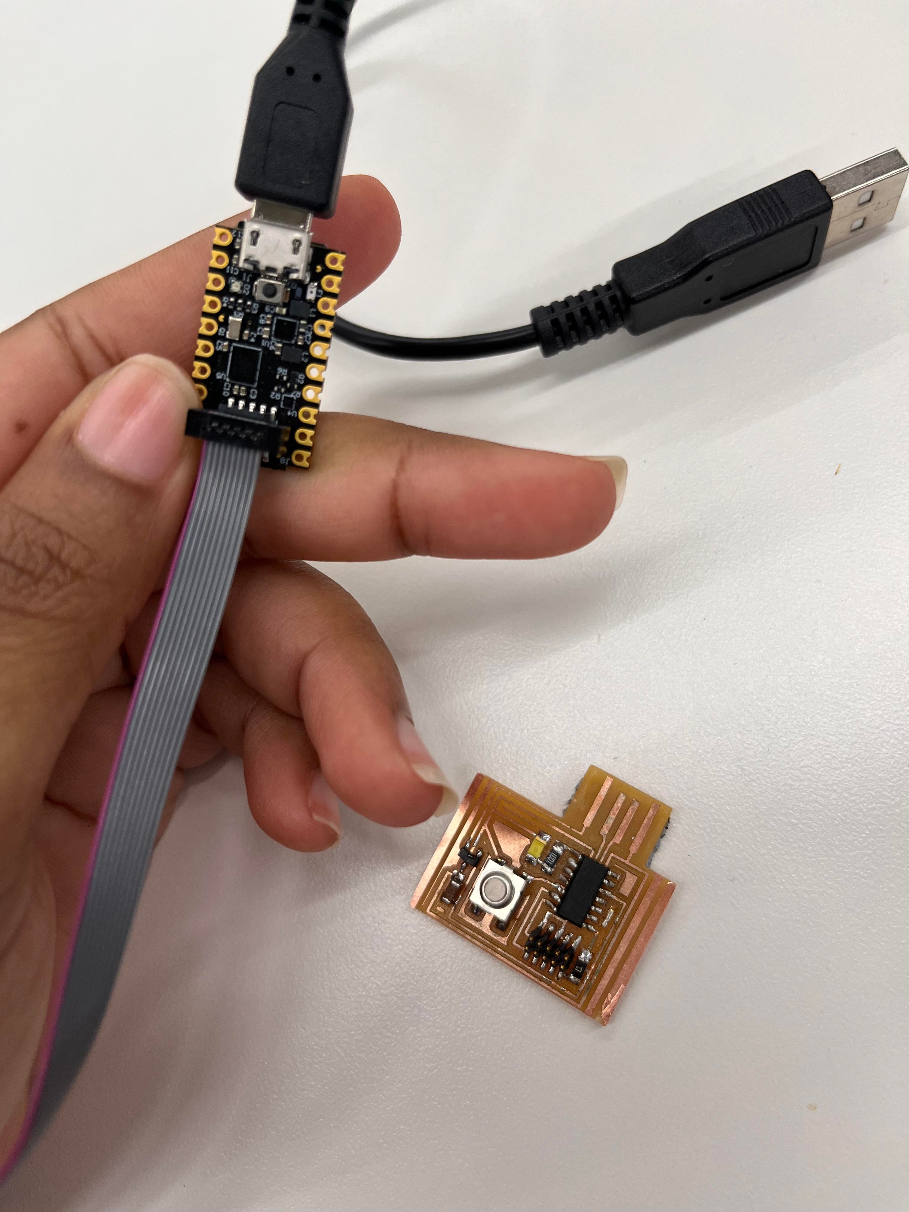
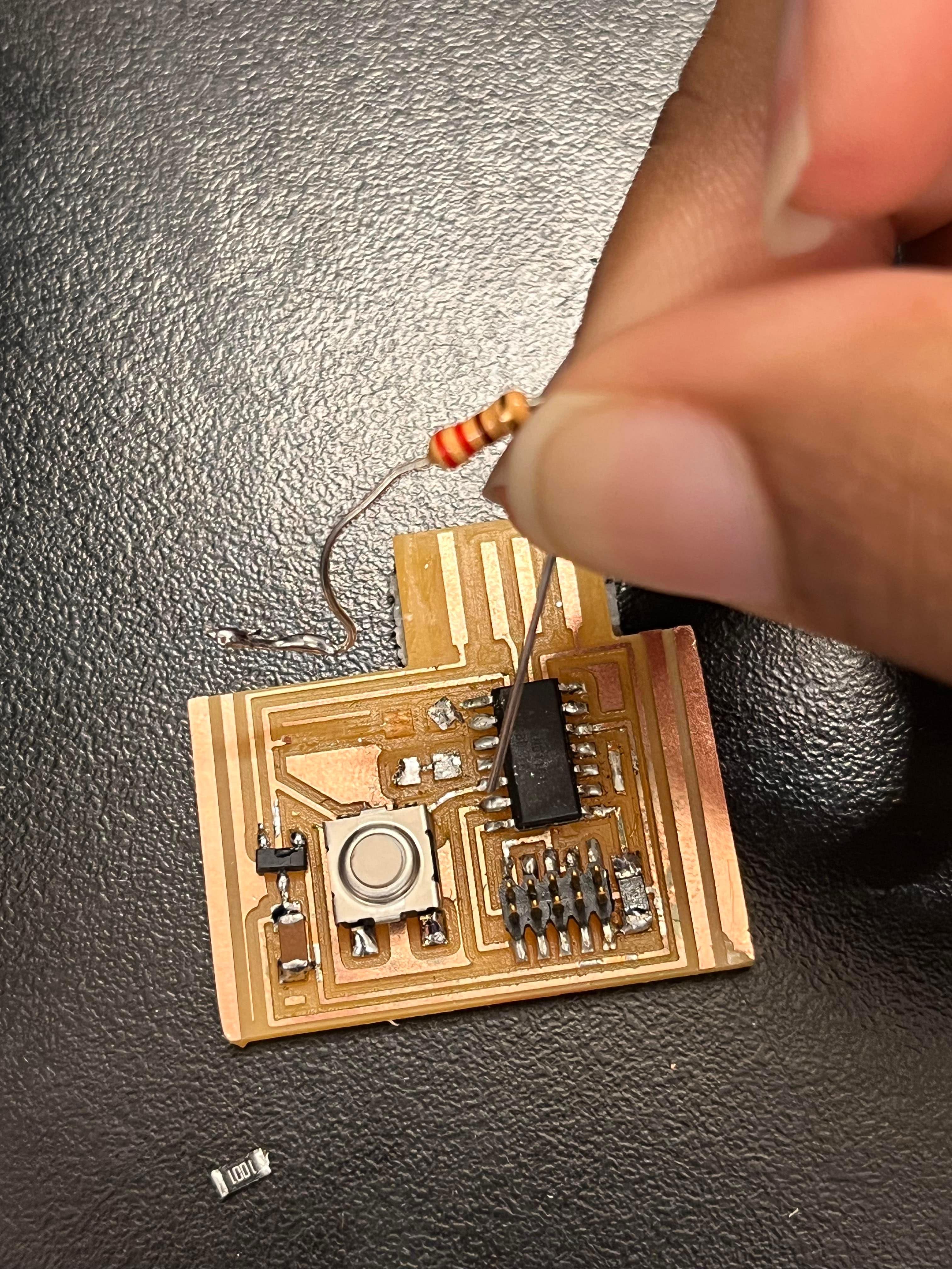
Suvin helped me successfully program my board! But my LED was not working. In my attempt to remove the LED and switch it around, the pads for it came off. I was advised to solder a resistor to the board to fix the issue, but I ended up ripping off more significant traces in my attempts to fix the board.
I went through the proccess again and created a new board. Unfortunatley there was a short with the traces that I unsccesfully tried to manually fix.
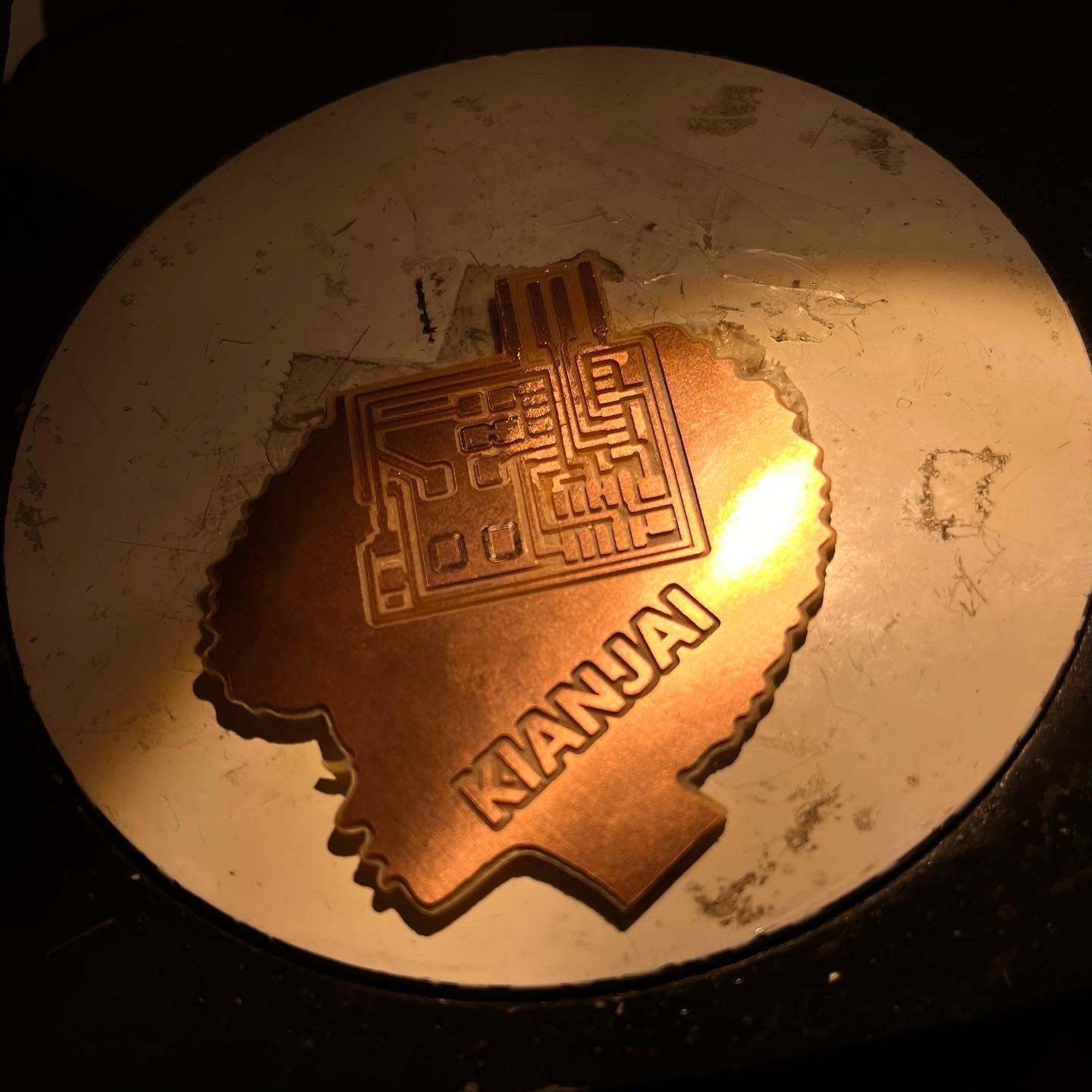
I was inspired by my clasmates to create a fun board design. The scaling was off, so I wasn;t able to solder the components, but I like the design.