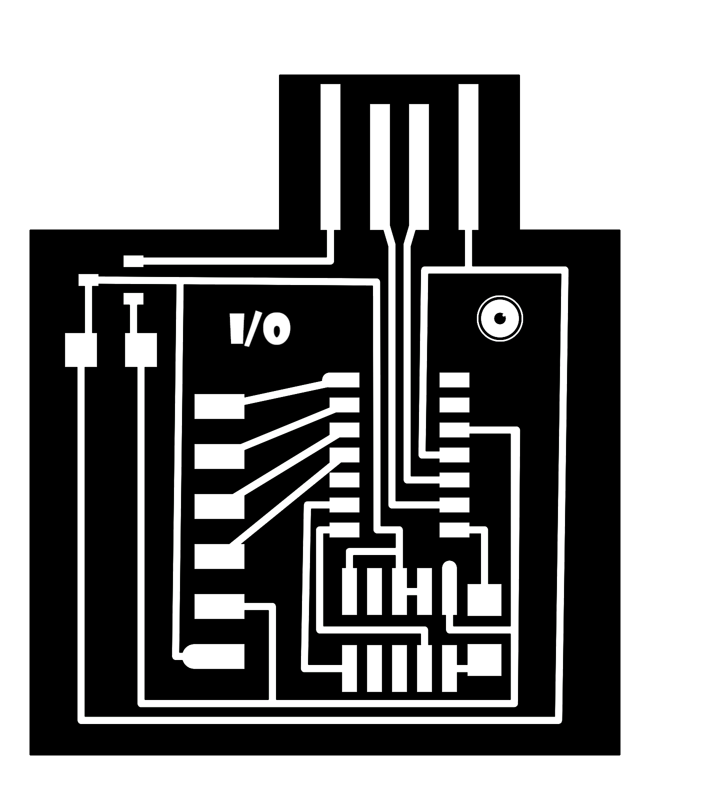
I wanted to use a soil mosture sensor and light sensor in my final project. I created a D11 board with extra pins in SVG-PCB & added some fun designs. The pins I chose to connect were based on the D11 datasheet, From here I chose to have the following pins be available via pins: GND, VCC, A05, A08, A09, & A14.
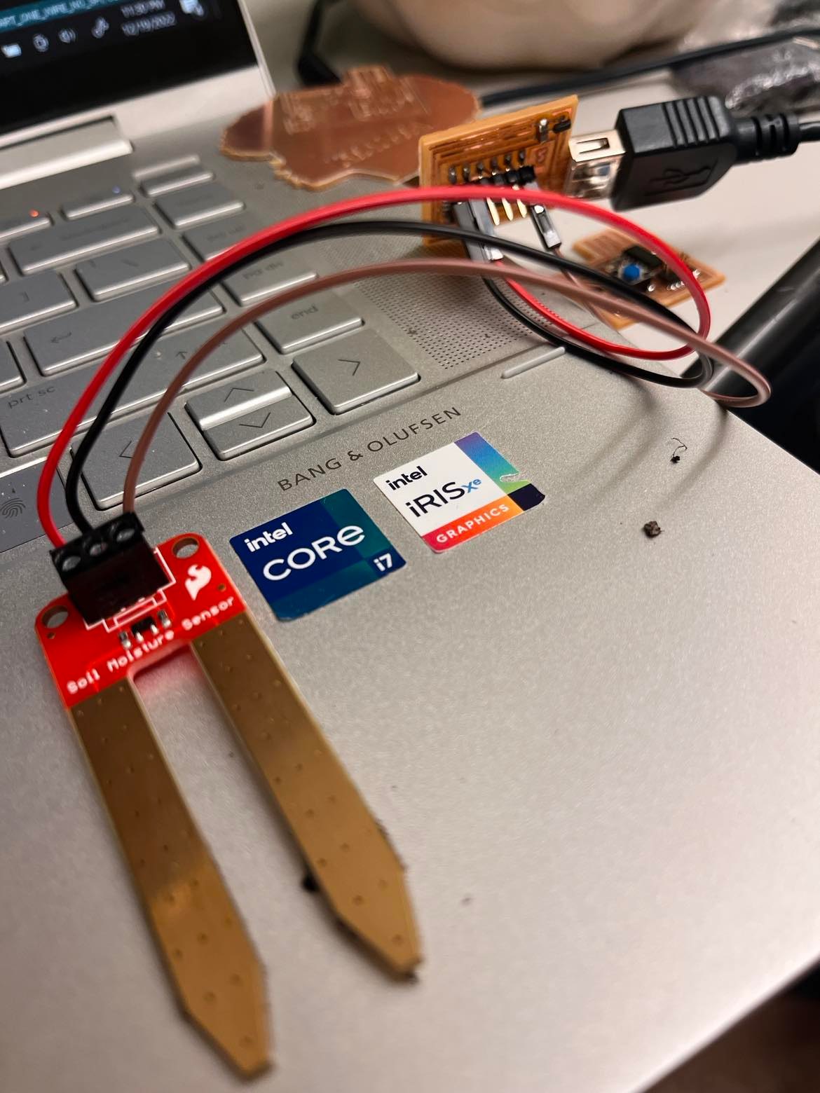
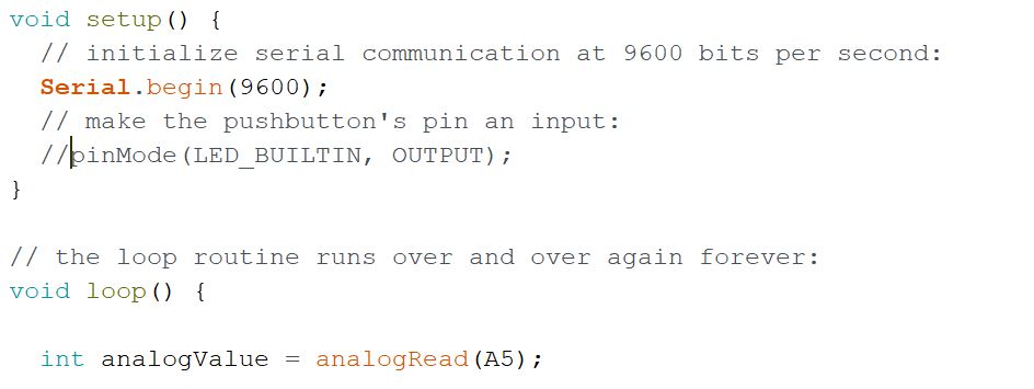
I started testing with the soil sensor and printed the analog values to the screen. Wiring was pretty straight forwad as it was labled on the sensor.
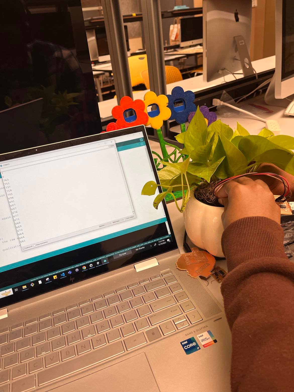
I printed the analog values to the serial plotter and observe the feedback by placing the sensor into my plant. The valueswhen the sensor was in wet soil is over 700. When the sensor was out of the soil, it read around 0.
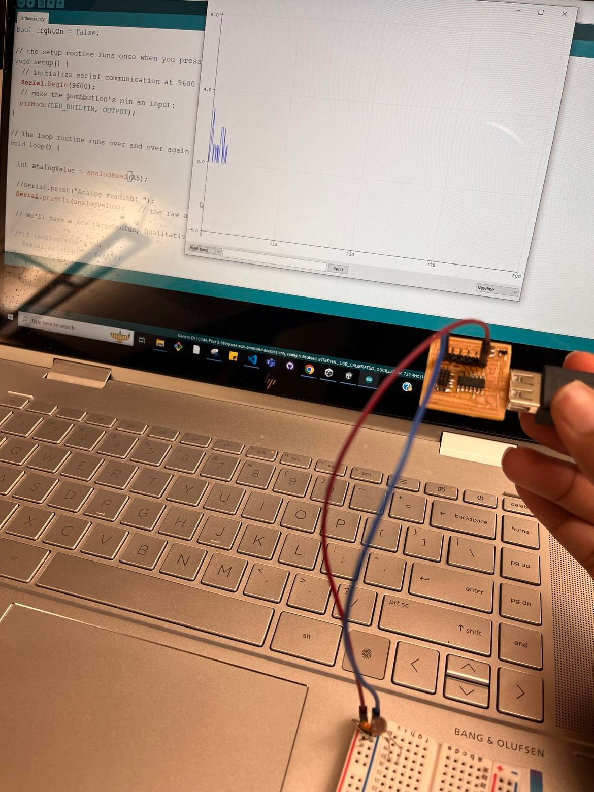
Secondly, I tested the light sensor. I didn't realize that I needed a resistor and that the photoresistor did not only take power and ground. I recieved some feedback in the serial plotter, and it helped me realize the sensor was not being read correctly.
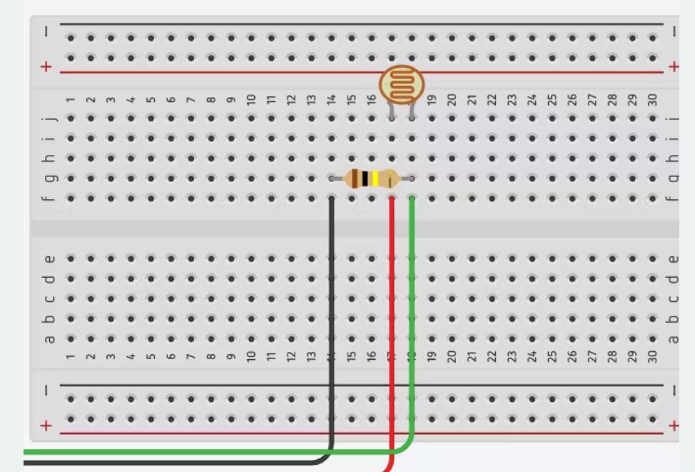
I corrected the wiring by following this diagram.
Demo - when it worked correctly!