Final Project
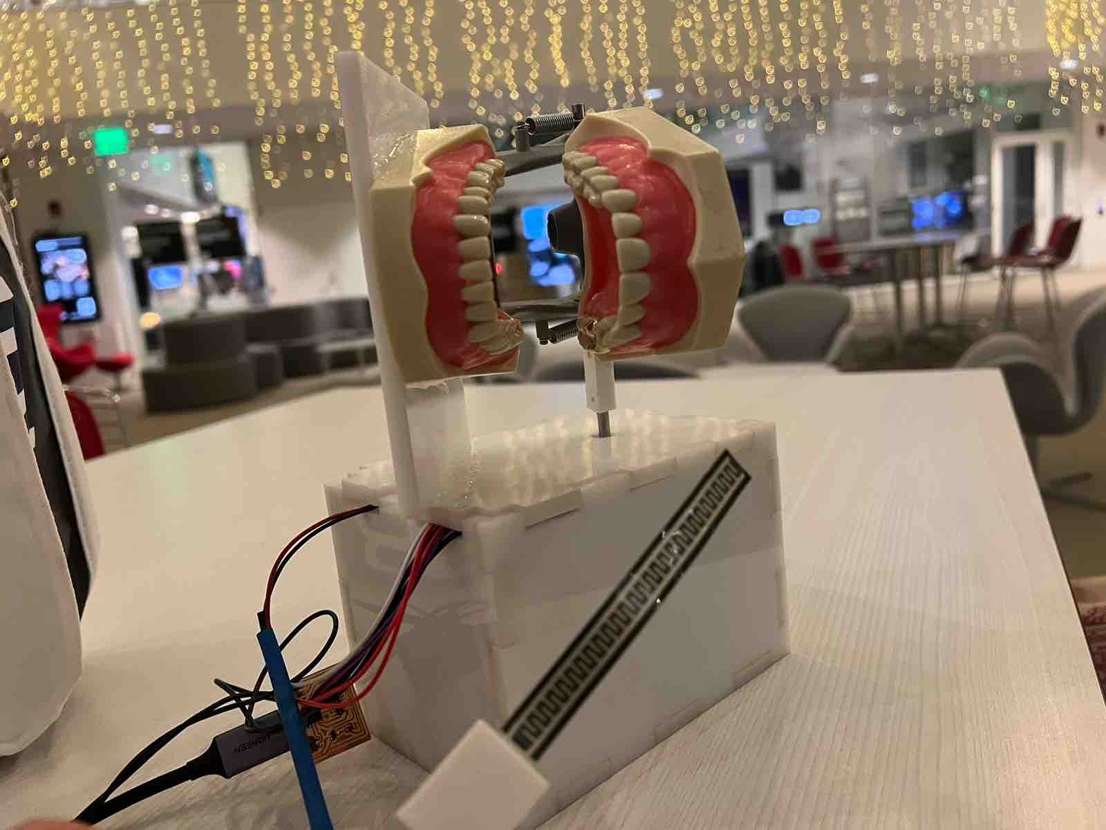
For the final project I made a jaw with a motor that allows it to bite down and open.
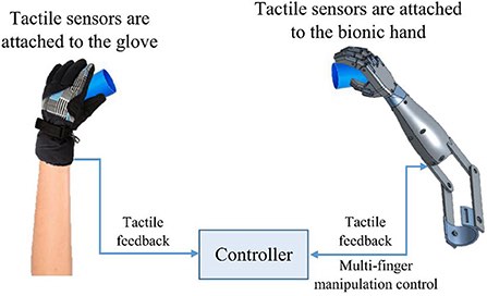
I will add sensors that I will put in the mouht to capture the movement of the jaws in the mouth and then transfer the information to the motor do make the movement in the synthetic jaw that I will make.
Initially I wanted to make it move like an actual jaw with all the possible movements for the tempromandibular joint, but I will make it more in on axis and have it mimick the biting down movement.
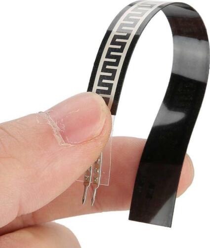
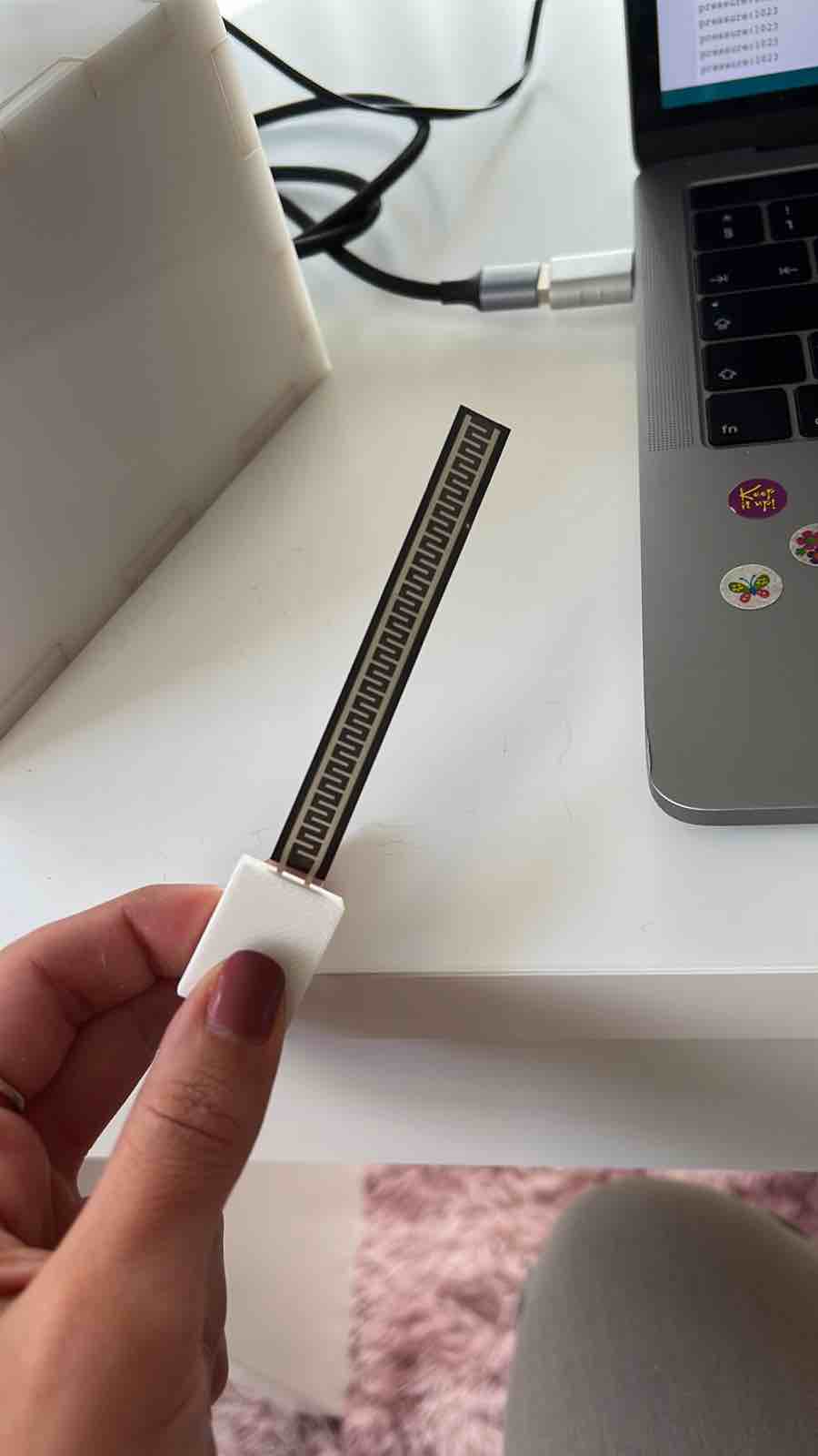
I will add a pressure sensor (Thin Film Pressure Sensor Flex/Bend Sensor) to the synthetic jaw to measure the bite force when the jaw bite downs.
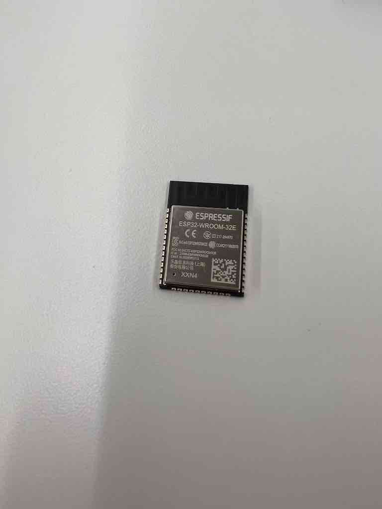
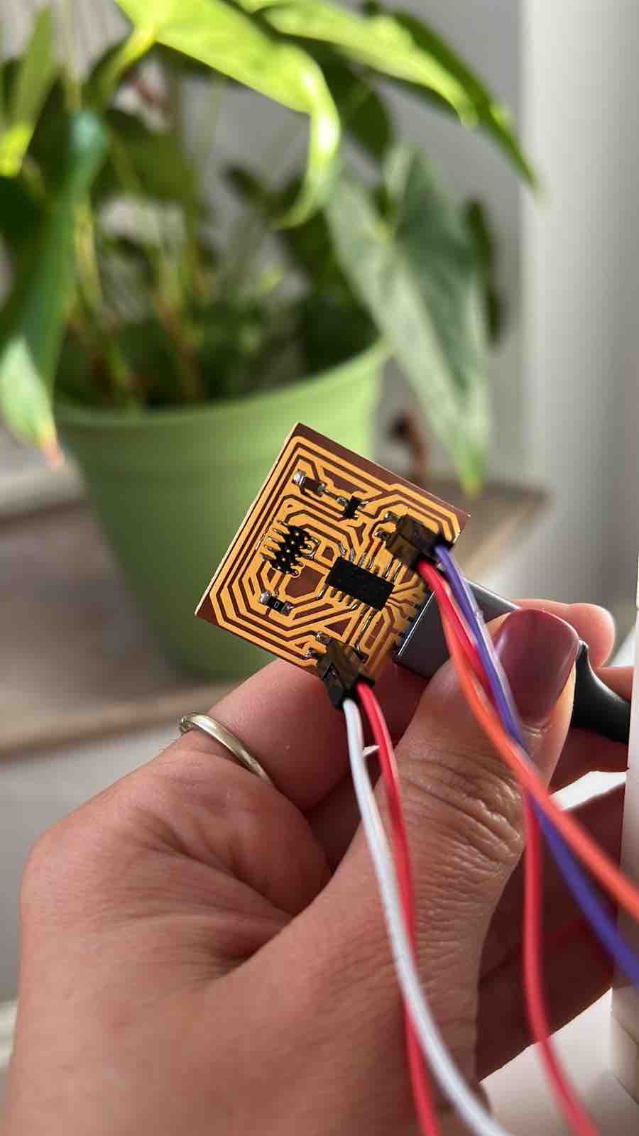
In order to do that I decied to design an ESP32 PCB to run the programs and communicate with an interface wirelessly.
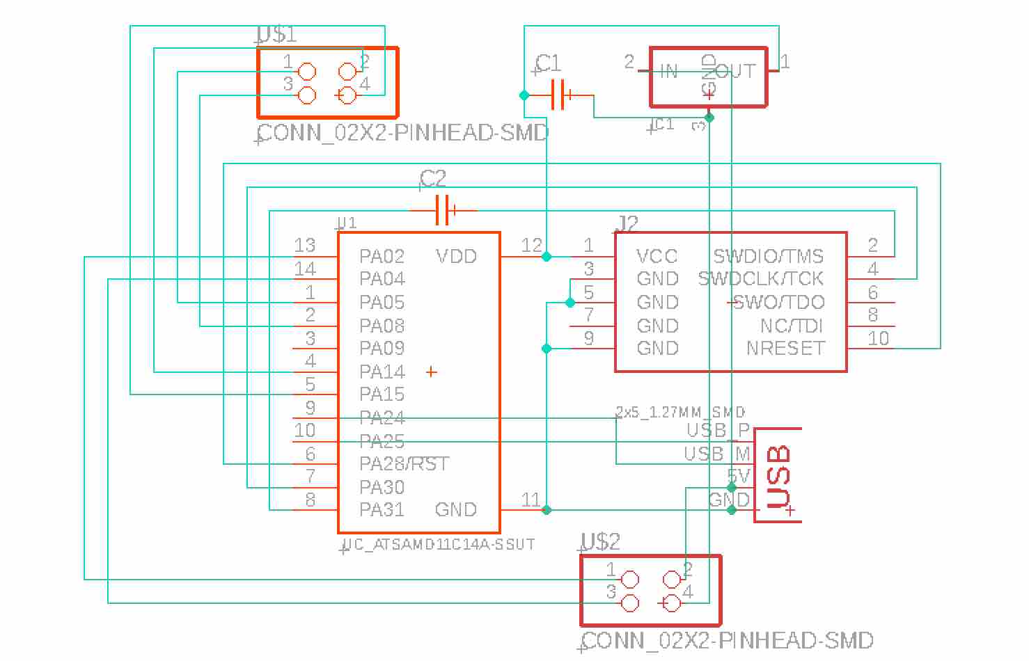
I used the help of a previous desgin to make my schematic and design my board for the ESP32.
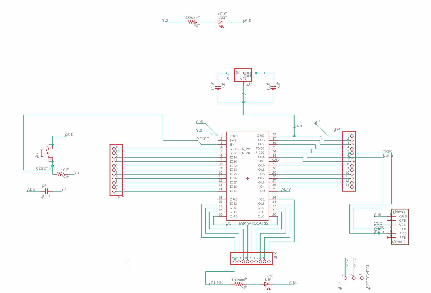
This is the schematic for my board using eagle in fusion 360.
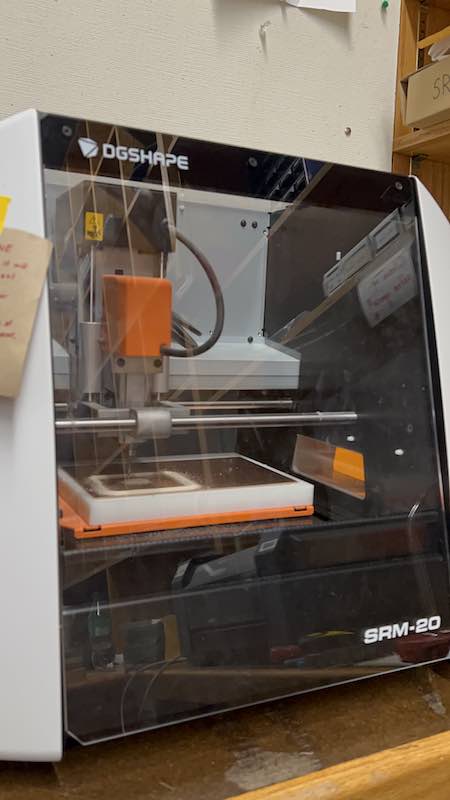
I milled the board.

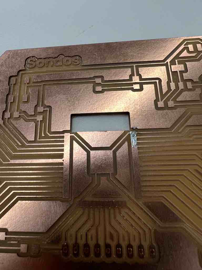
But the pads came connected because the clearance between them wasn't enough for the drill pit to clear and mill through.


So I had to adjust the footprint of the ESP32 that I used, to adjust the clearnace between the pads, you can see the differenc ei n the size between the first and the second pad
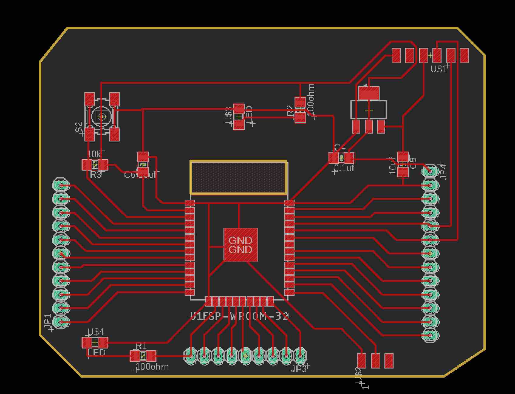
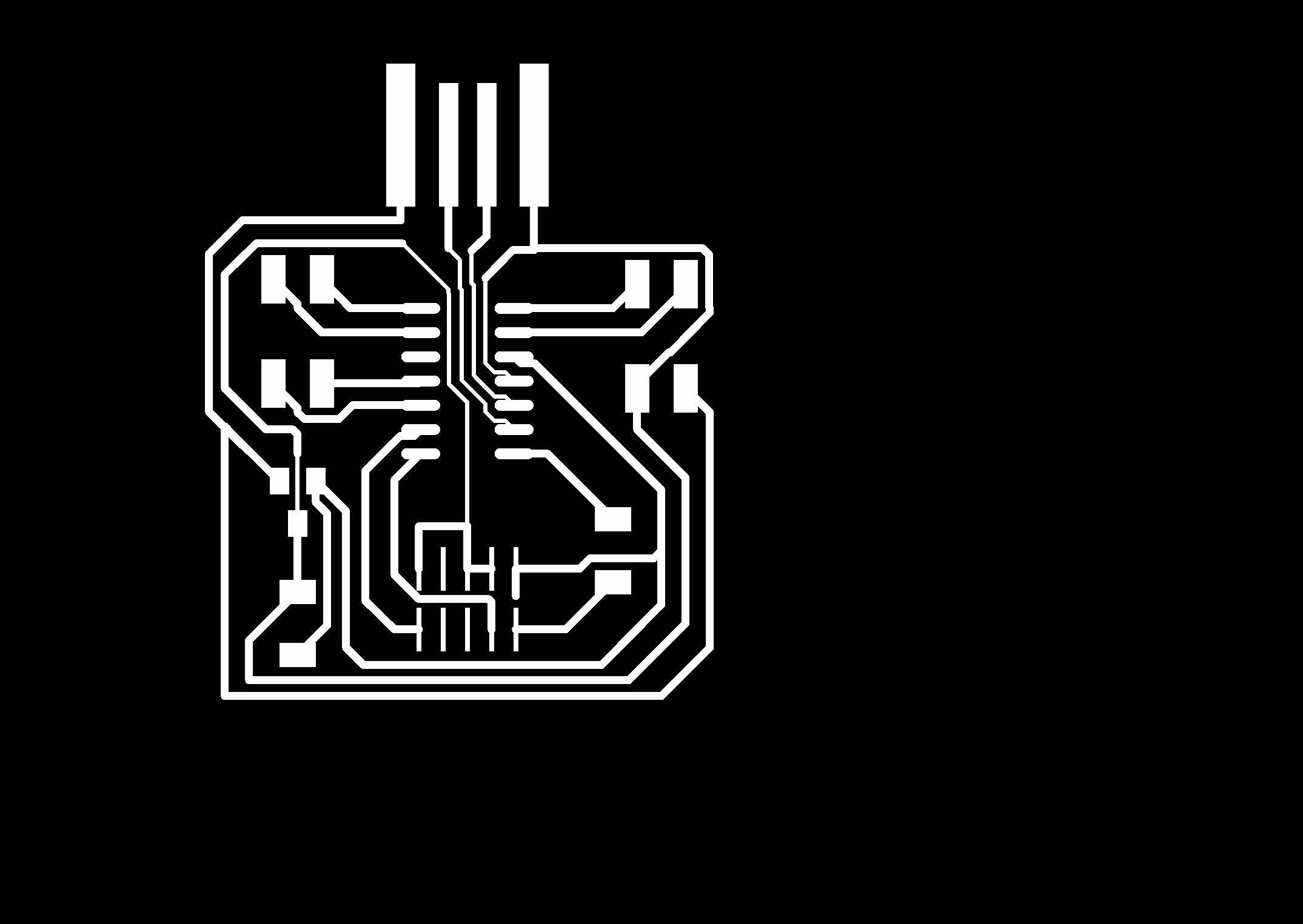
I made sure the clewrance was 17 mil and there was clearance between the pads, and made the tracings for my PCB.
Here is the final design of my PCB, ready to be milled. I milled the traces, then holes, then outline.
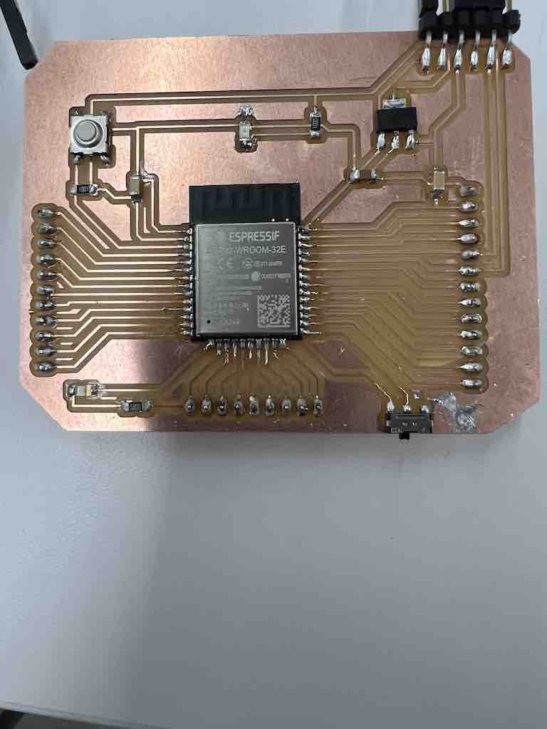
Then I milled the board again and it worked and I had clearance required for each pad to be seperate, and I was able to solder the parts.
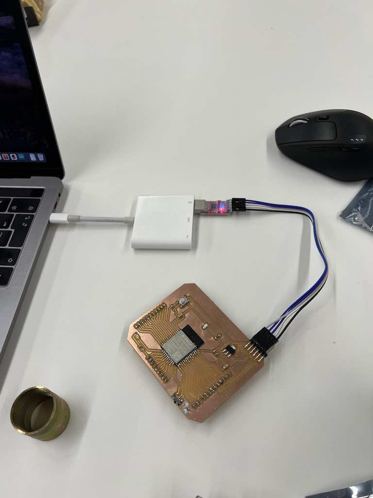
I used the connection to connect the board to my laptop and programmed it to light the LED.
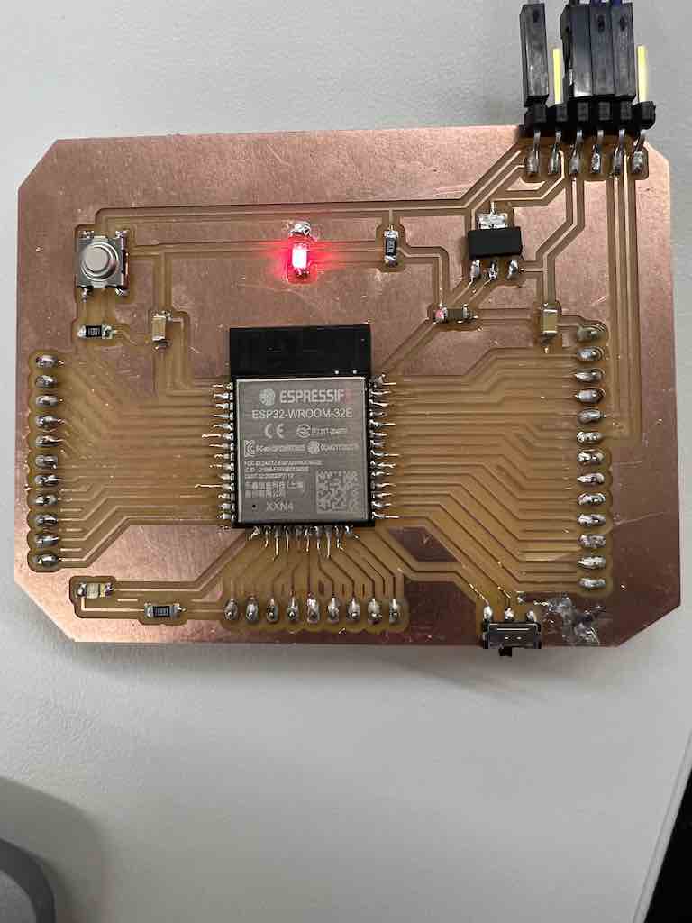
And this is the final look of my board, with the LED on. And I will use it to program other sensors for my next projects
The ESP32 worked with my pressure sensor but did not work with the steper motor. It took me 2 days debugging to figure out howt o fix it and what was the reason behind that but I did not know the exact reason. Maybe it had to do with the digital analog because it works with the pressure sensor. I decided not to waste time trying to have the ESP32 tto work, becuase other microprocessors can do the jobs I wanted to do. I decided to use SAMD11 PCB, it has all the pins I need to run my motor and the sensor, I wouldn't be able to connect it to WIFI for my interface, but then also to get past that I decided to do the interface locally in my laptop.

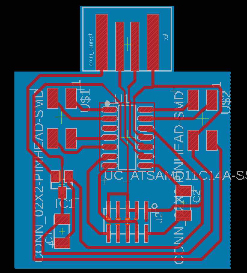
I made simple SMAD11 PCB to ge the job done, I used one analog and 2 digital pins for the pressure sensor and the stepper motor, respectivly.
I wanted to use the pressure sensor to measure the bite force. and have the jaw bite down using a stepper motor, but then I thought of a better idea, to have the motor and the sensor communicate so when I bite down on the sensor it senses the pressue and the signal is given to the motor to turn to a certain degree. The starting position would be an open mouth and then it will turn to close the jaw when pressure is applied on the sensor aka biting down on it.
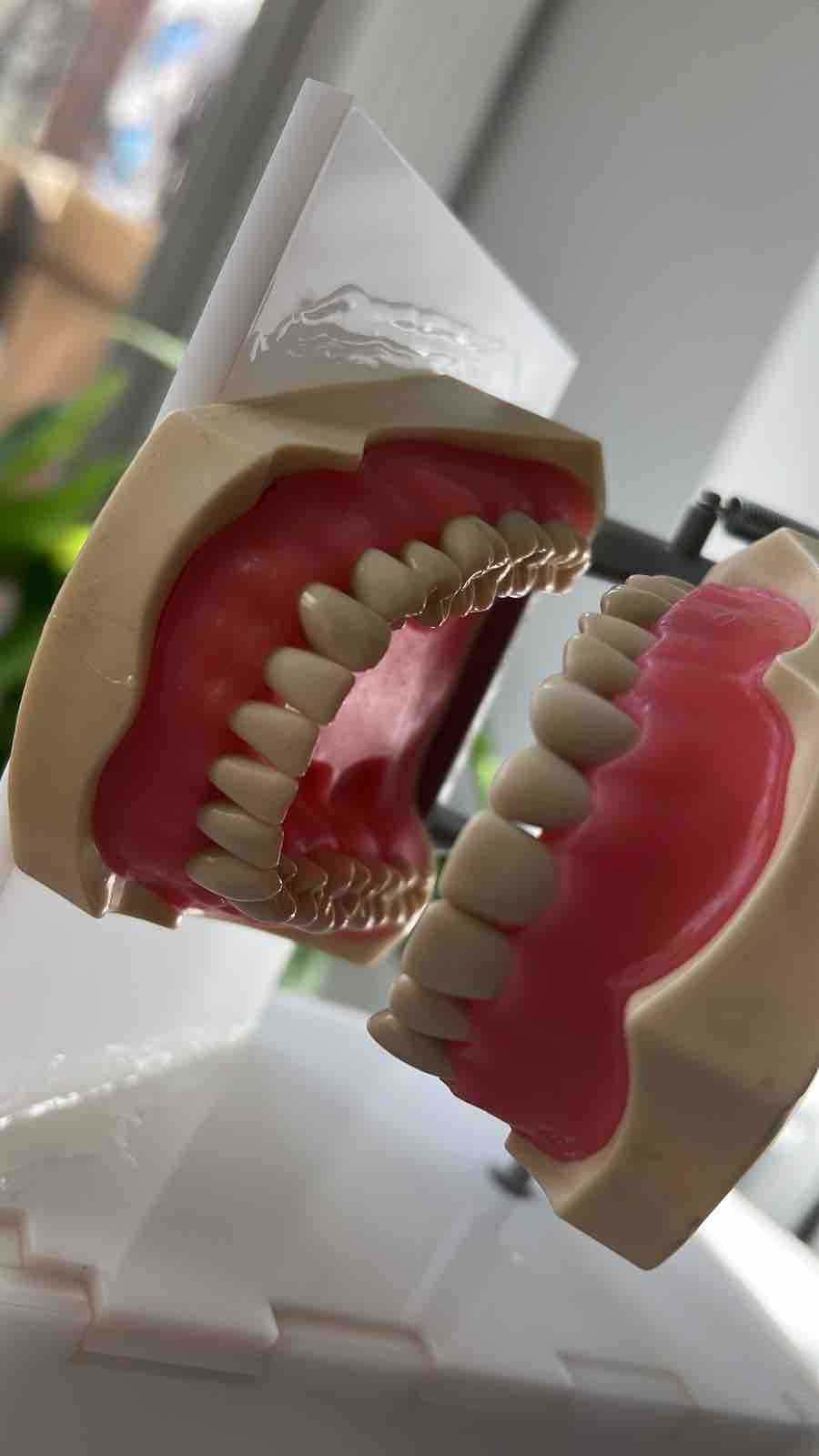
This is the jaw I used to connect to the stepper motor
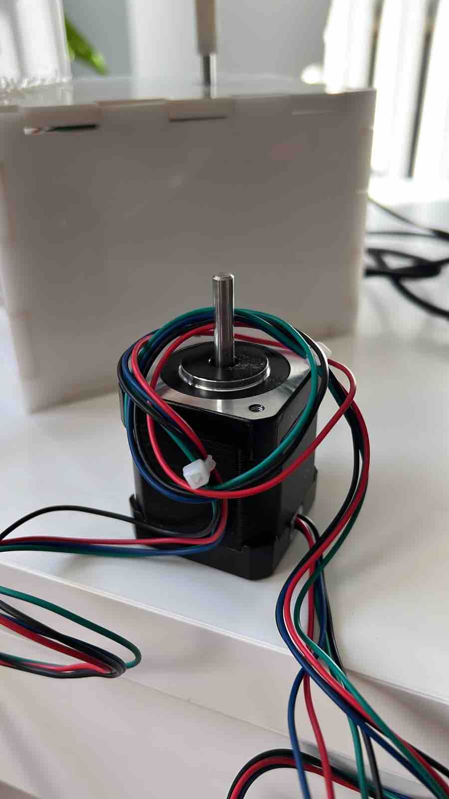
I used this stepper motor, and connected it to 12V to power it, I used A9488 chip to operate the stepper motorand made the connections for it.
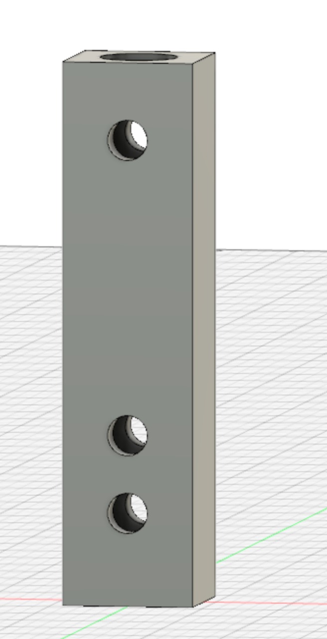

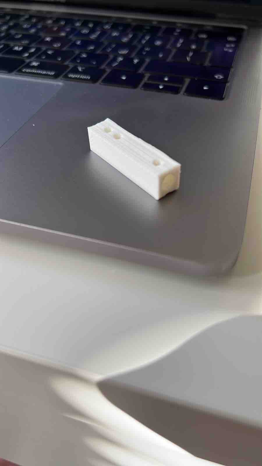
I designed and 3D printed the part that connects the stepper motor to the jaw to operate, so they would be tightly connected and move together.
Here is the connections I made to the SAMD11 PCB to operate both the sensor and the motor
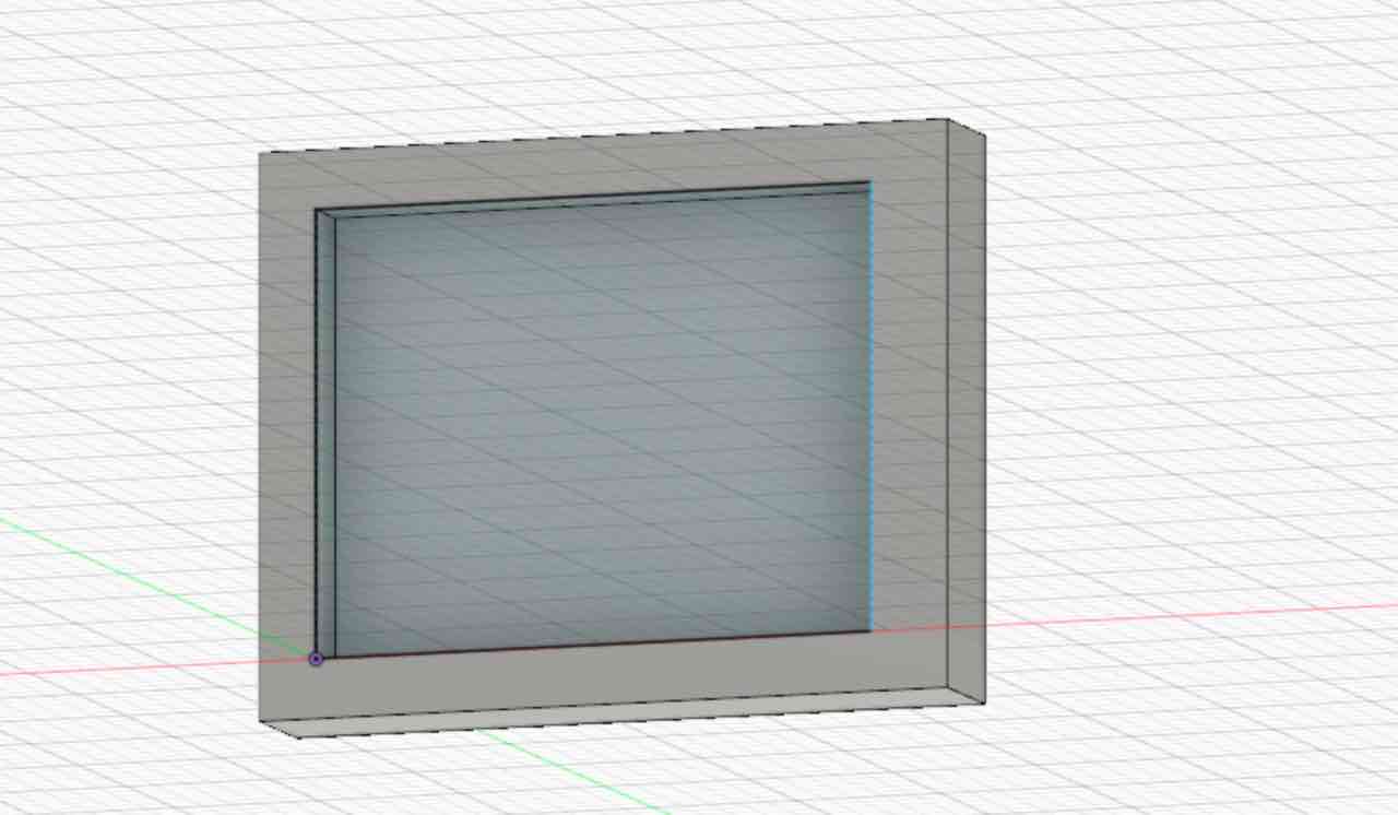
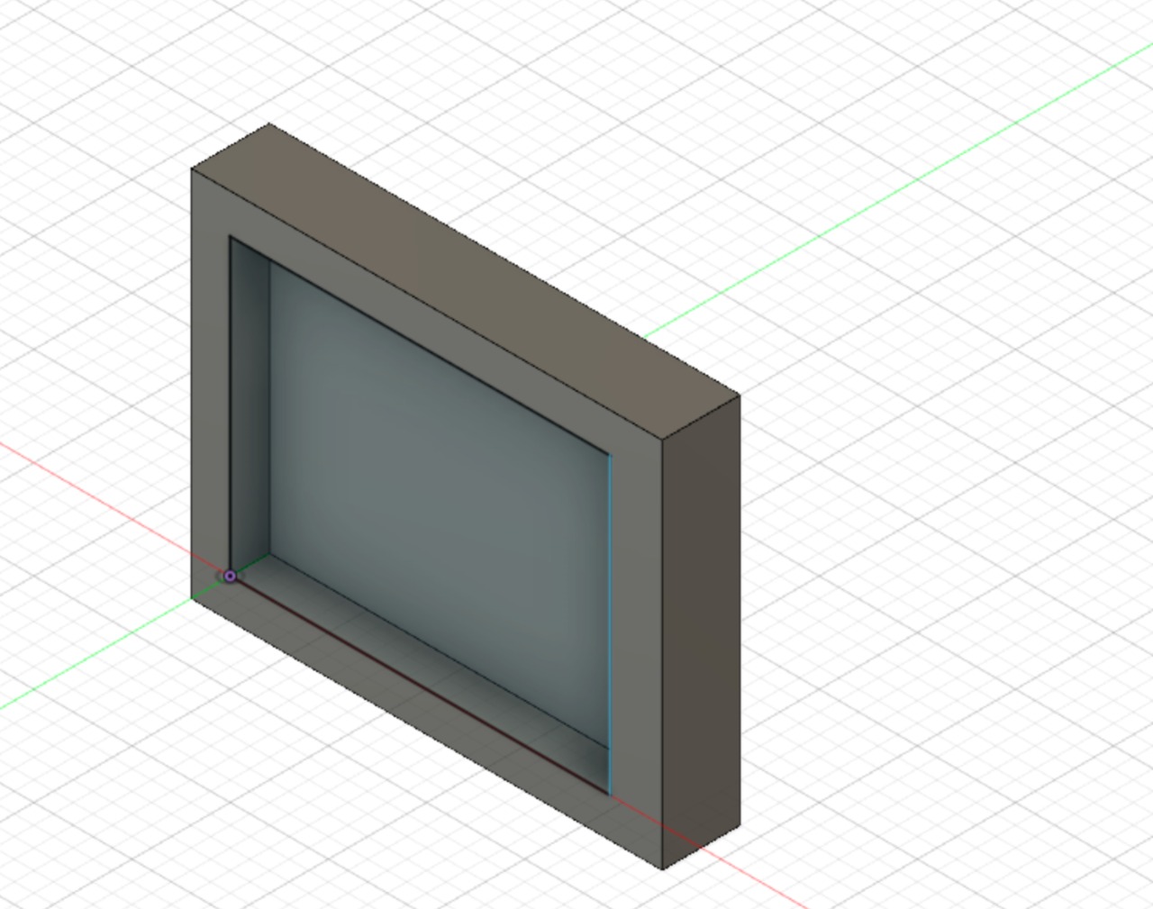
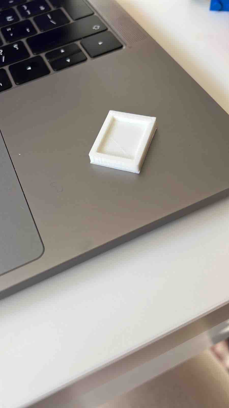
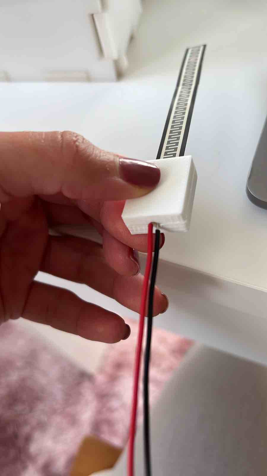
To be able to hold the pressure sensor without causing it to react and also to conseal the wiring and the soldering that I did I designed and 3D printed a holder, I made an opening inthe bottom to allow for the wires to go through.
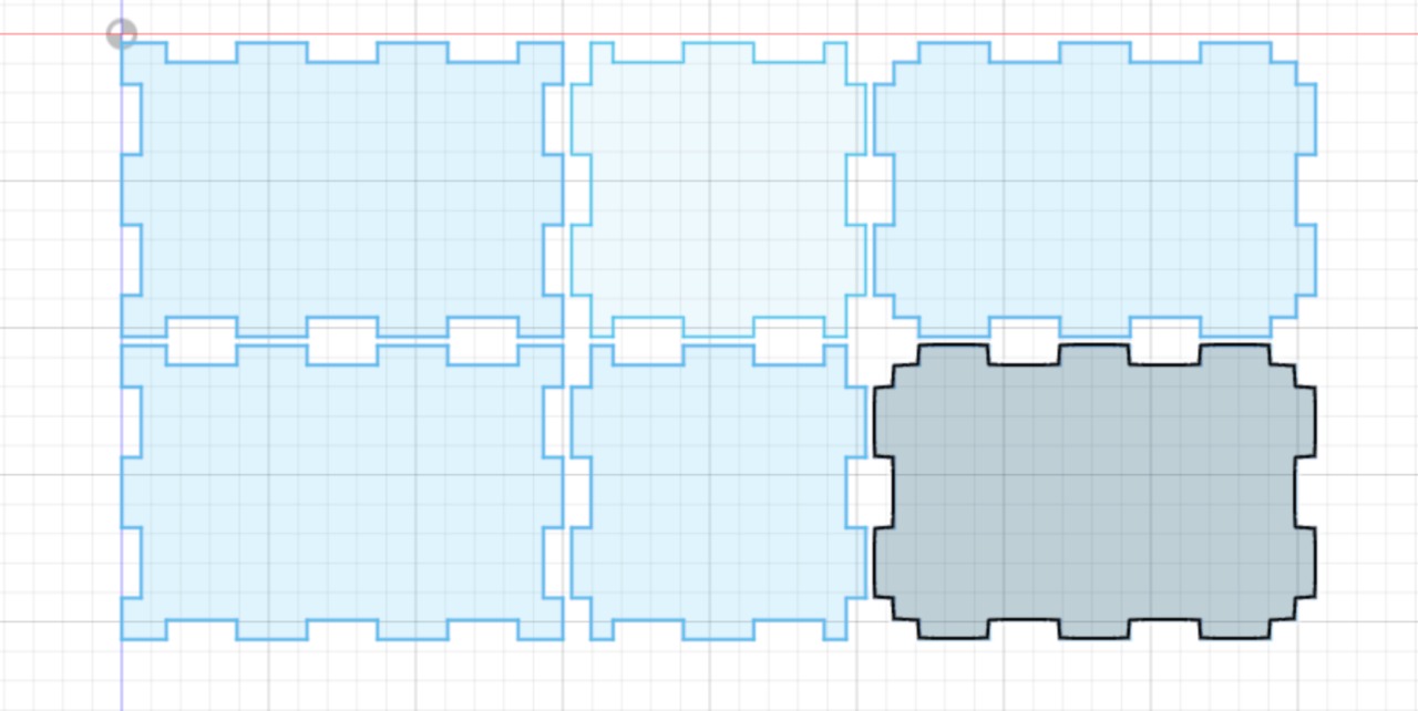
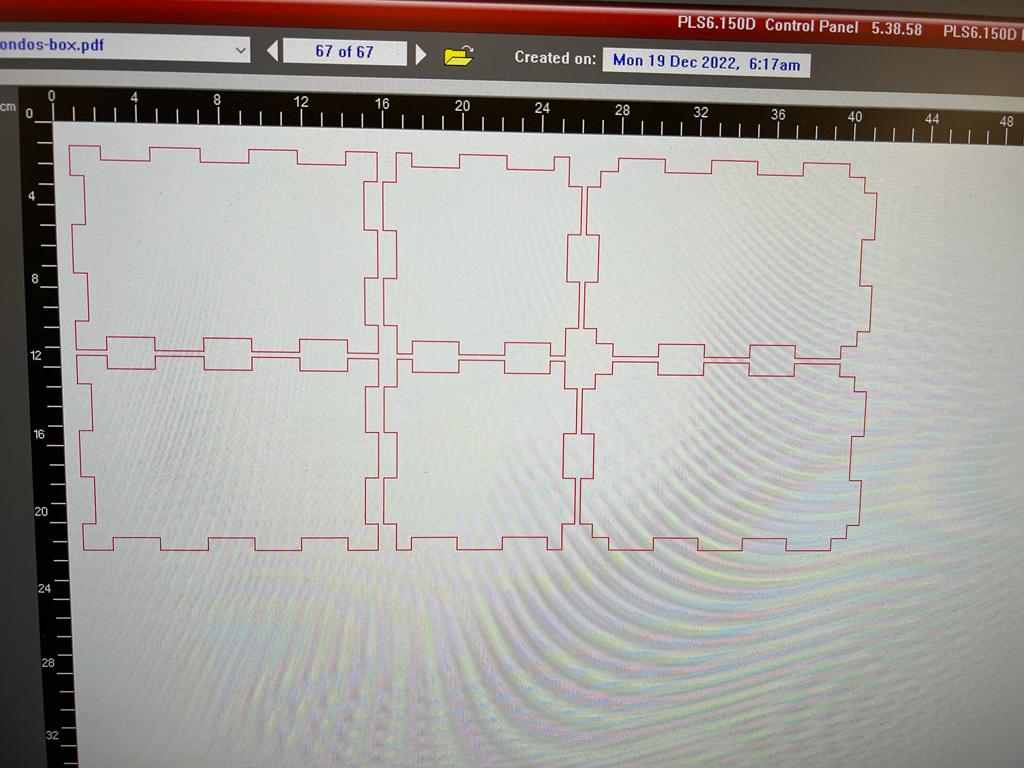
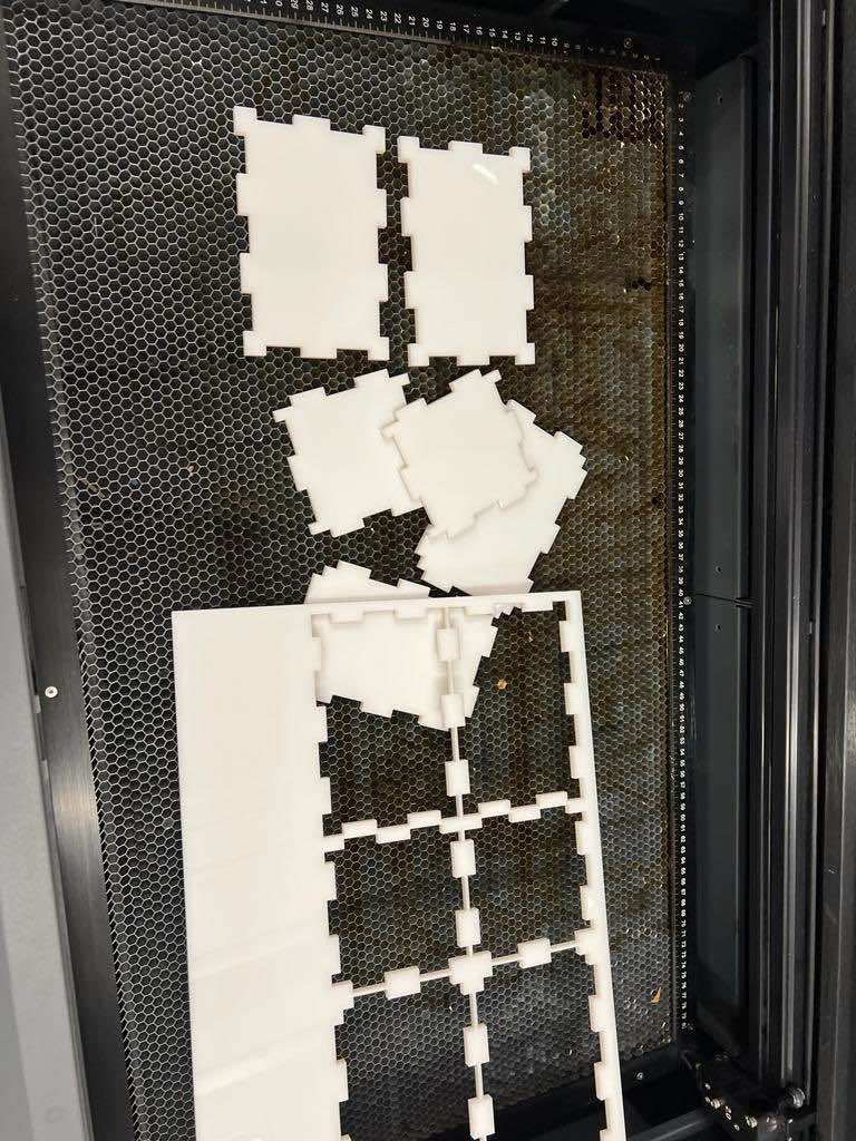
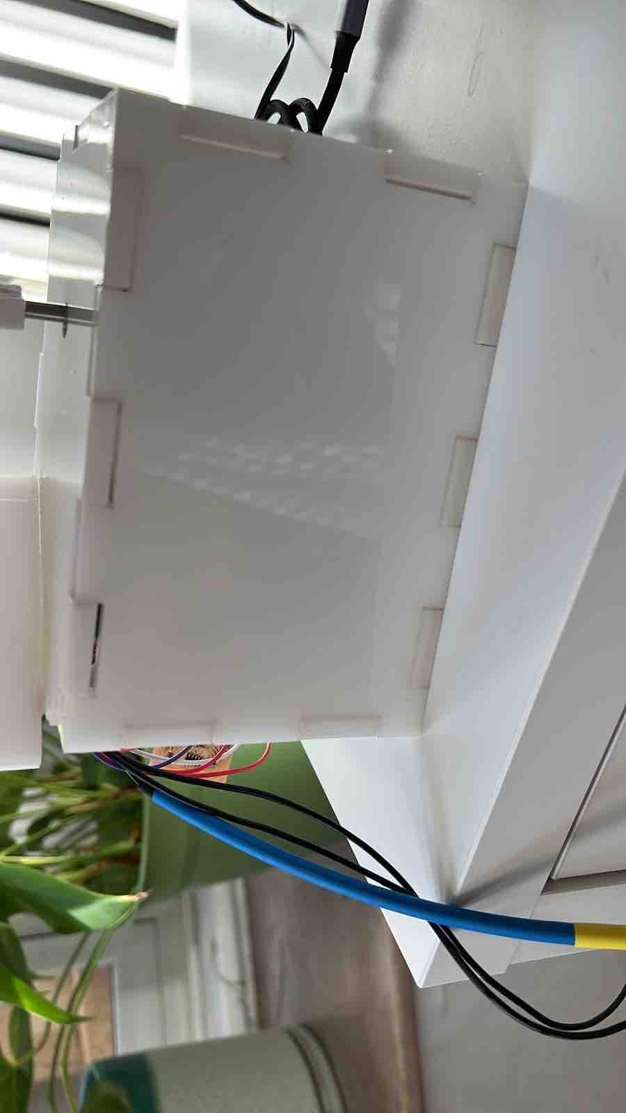
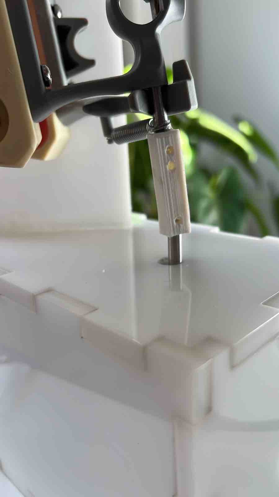
To hold the components together and to have a place to put the pressures sensor and the wires I designed and laser cut the box for it, and then made a hole for the motor head to go through and connect that to the jaw holder. I fit the parts together and used epoxy glue to connect them together
Here I'm assembling the box and holding the jaw in place so there will not be strain on the connector (between the motor and the jaw holder).
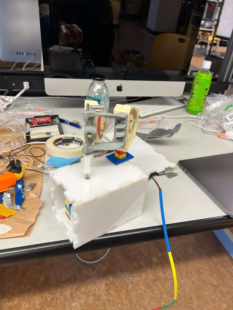
Some of the challenges I faced along the way: - Determining the angle for the jaw movement with the motor was not an easy task, I had to go over many times to get it to the point where it turns up to 70 degrees to mimick an actual jaw movement of a normal person. - Another challenge to map the pressure sensor reading and connect them with the jaw movement. Initially I thought of having 3 specific turns. 1. Full open mouth, 2. Half open mouth 3. Completely closed mouth. But mapping that and making the connection was not easy. With many trials, I was able to make a continuos movement for the jaw where in each increase in the pressure there would be a corresponding movement towards turning movement (closing the mouth) untill completer closuer will occur. This was the most challenging part to figure out. - another one was to hold the motor in place and reduce the noice when it moves, so I used materials that would act as a cushin for the motor and also hold it at the desired angle and place. - Then I encountered a challenge after I assembeled the jaw and the motor and tightly got them together. The jaw was too heavy for the motor to perform the open movement (turning it upwards against gravity), so I thought of adding a compression spring to help push it upwards, that was helpful to push it up but then created challenge to close it back and turn it down since the resistance was more than what the motor could handle, after many failed ideas using different materials I ended up turning it to the side, where gravity would not interfere with the movements that I wanted to have the jaw make. - After I decided to hold the jaw vertical rather than horizontal, I encounttered another challenge; which is the strain that would be placed on the link between the motor and the jaw, so I had to hold it in place to remove that. On top of that there was not anything to hold the other part (lower jaw) in place so now both the jaws are turning in the air, so creating a base for the lower jaw was the next step. I laser cut a part of the acrylicv material that I made the box with to go up to where the jaw in located and glued it using epoxy glue. - And many minor challenges along the way, like how to hide and organize the wires so it will not disconnect with moving it and to reduce the propability of errors occuring along the way
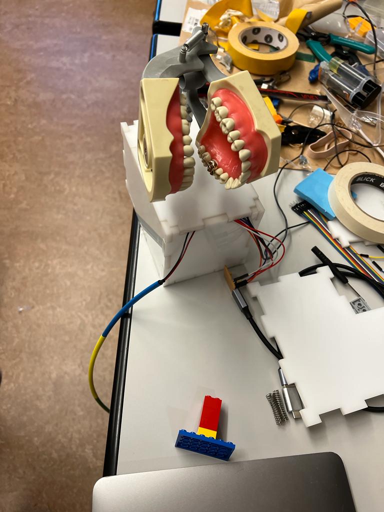
Here's a final look of my moving jaw, it was a GREAT learning experience, and life transforming as well. This is my first encounter with 95% of the concepts, the programs, the ways, the science and the huge amount of knowledge in this class; tackling all of this was me going through a VERY steep learning curve. one thing I know for sure is that this will only be the beginning of my learning experience, after I've seen all the possiblities of what I can learn and what I can make there is no going back, there is only moving forward. I will try to link all of what I learned here and will continue to learn to dentistry, and see what I can bring and what issues that I can solve thtat we face on our daily practice with what I learned, and will also try to move this knowledge to people who can benefit from it.
For me this was not only a learning experience but way to pivot and change my mindset and the way I approach life in general and the way to move forward in my career. Thank you for making this possibleHere's a link to a VIDEO of my final project!!! Hope you enjoy watching!!