This week we have to make network devices. My goal for this week is to successfully replicate an esp chip and make small modifications to it, with also some personalization.
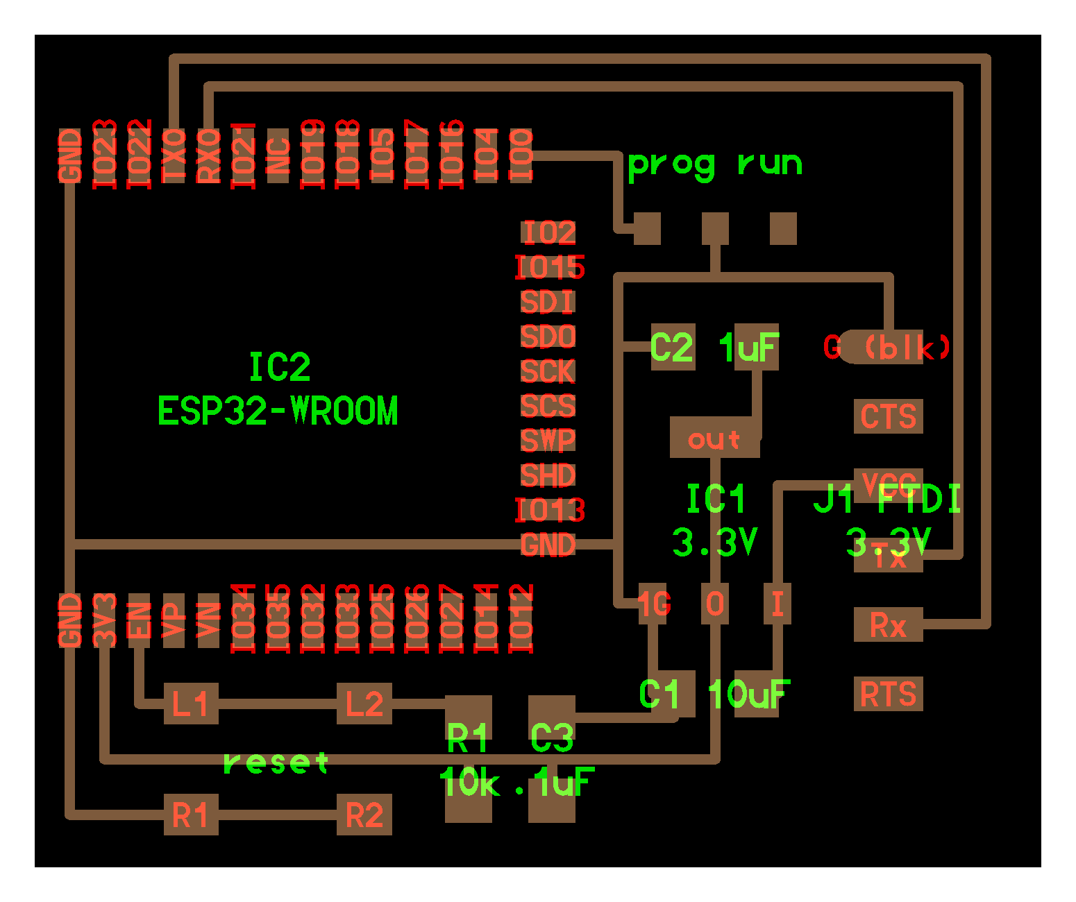
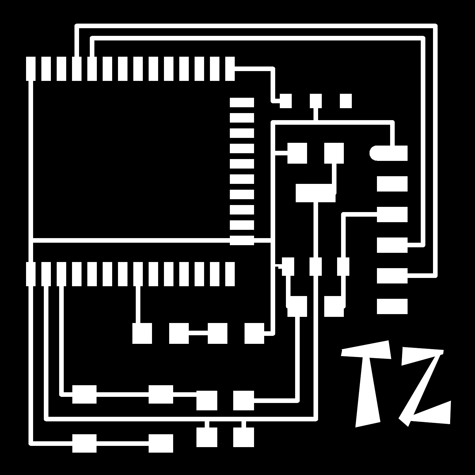
For the schematics I moved the bottom part of the chip down and added in a resistor and a led as an extra signal. I also added my initials on the lower right.
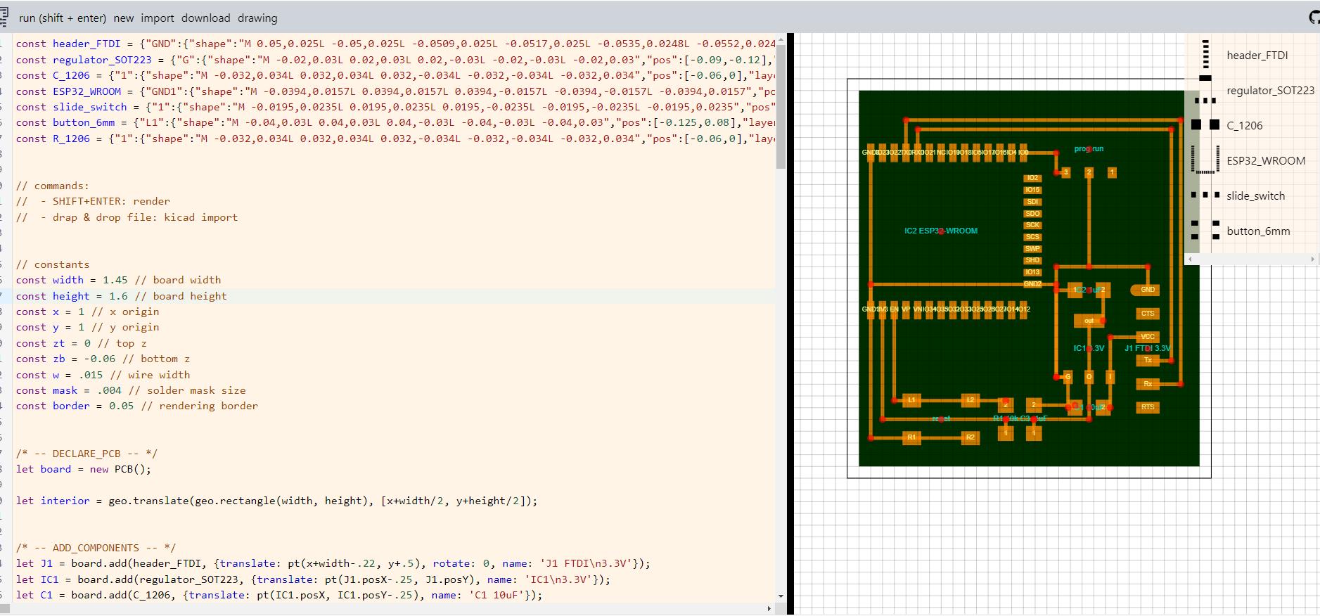
I tried to use svg pcb, however, I have a lot of problems to get it work, since you better have a decent level of computer science knowledge. The interface is a bit arcane for me, and there is no ctrl+z on the web ui. So I have to move into photoshop instead. In photoshop, I can directly edit the pixels

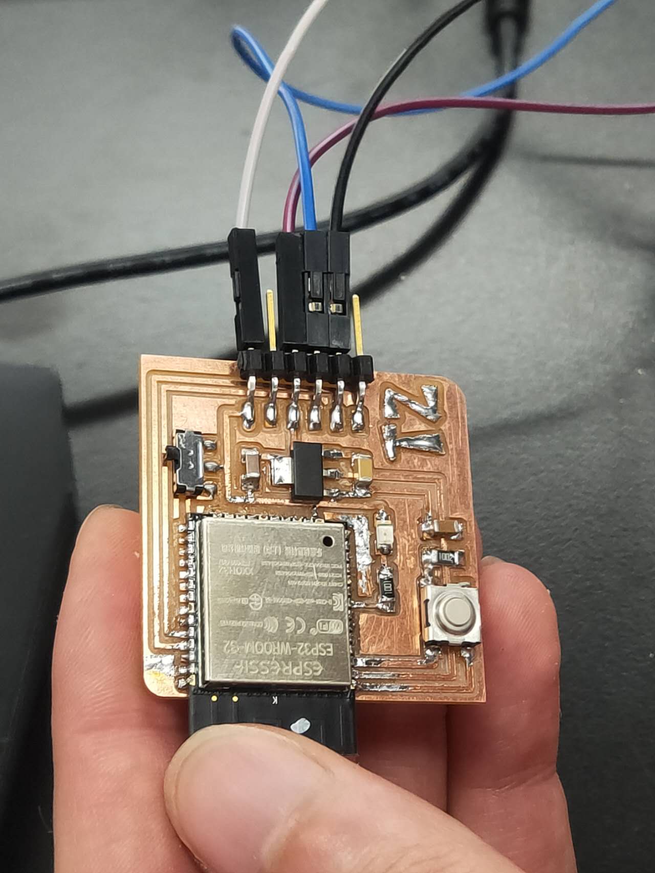
I had a hard time milling the board. Then, I solder all the components on it. The hardest part is to identify different capacitors. There are 0.1μF, 1μF, and 10μF, each are indicated by a small difference in their color. One is very dark yellow, one is medium yellow, another is bright yellow. Make sure you know which is which before you solder them on.
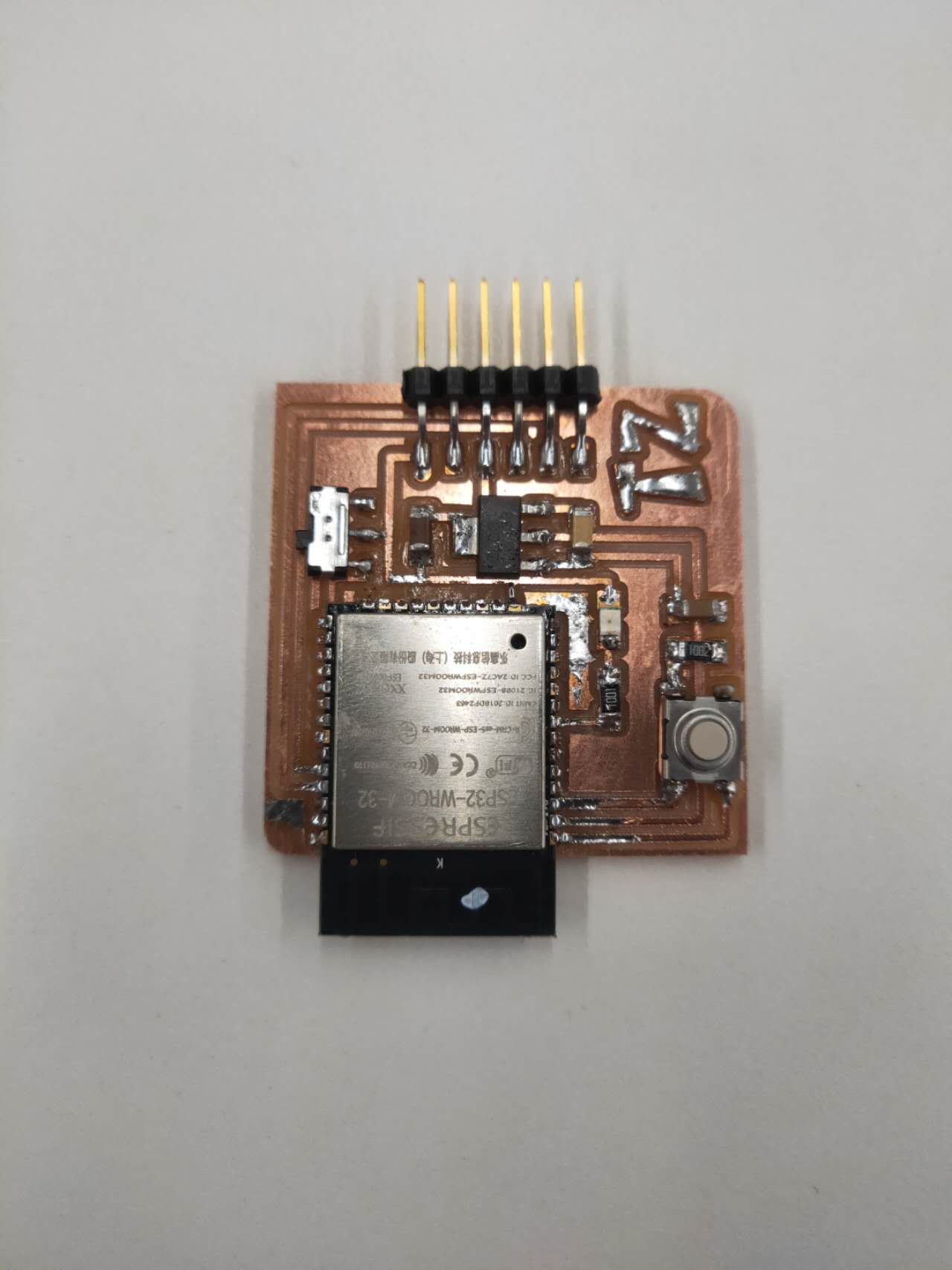
Other components like switch and connectors are fairly easy to put on
After the first week, I kept going to try to program it.
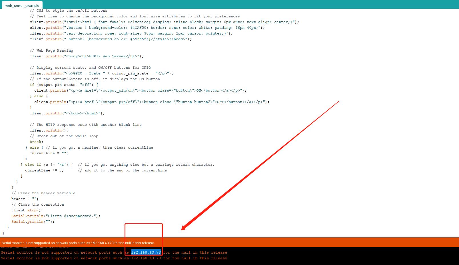
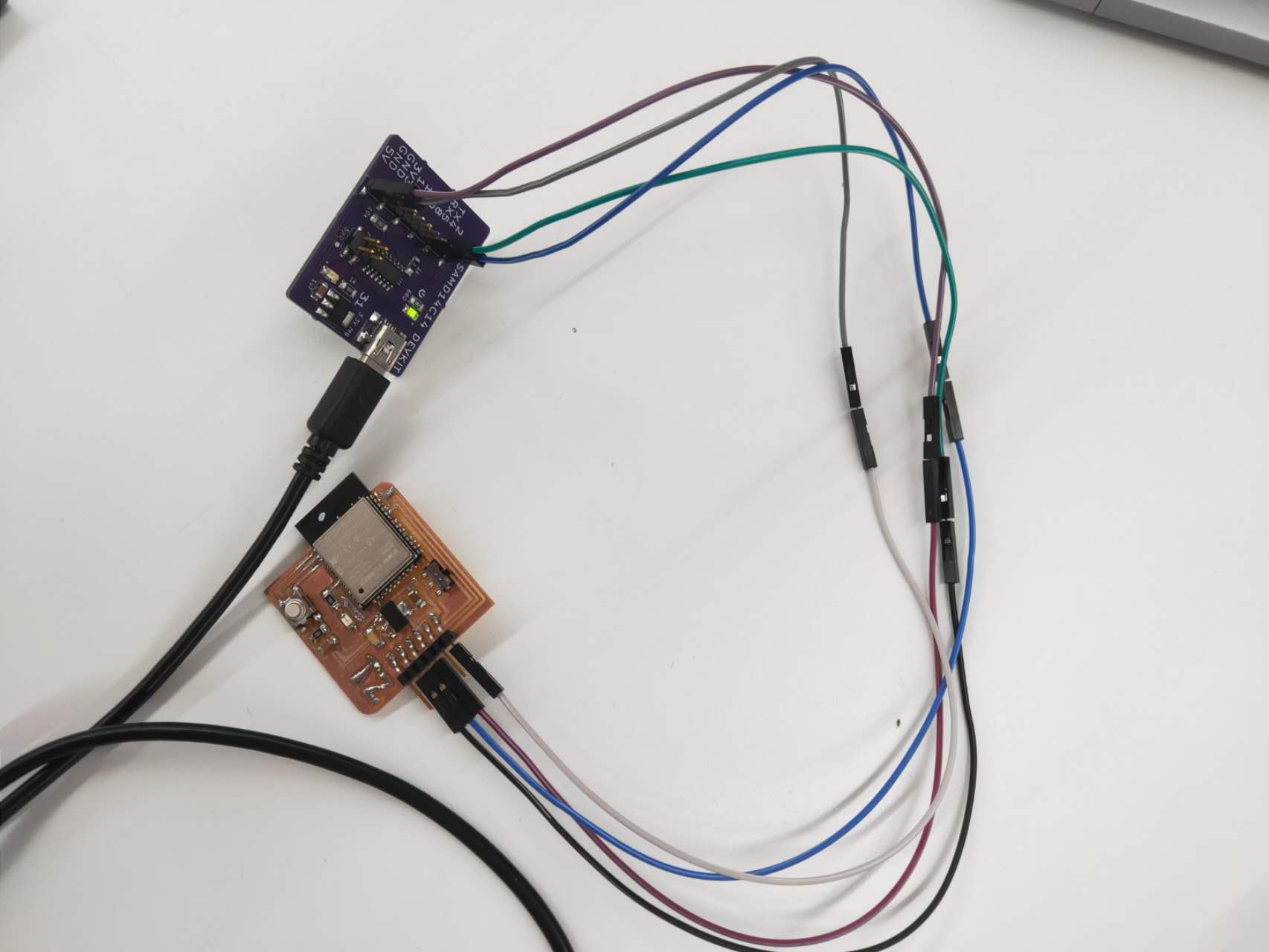
I copied Quentin's code for wifi control and try to program the board to be controlled by a web ui One need to make sure the board is first connected to the computer through an adapter which feeds into the six pins. There is a switch on the network pcb which allows me to turn it into "run" mode and "program" mode.
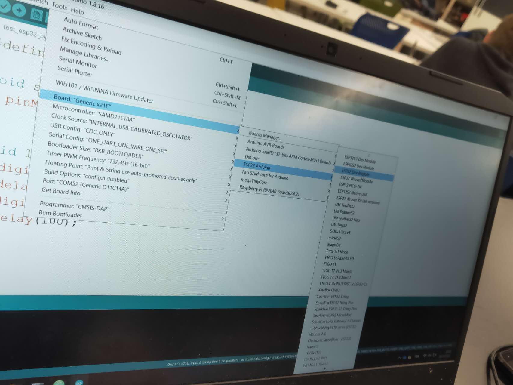
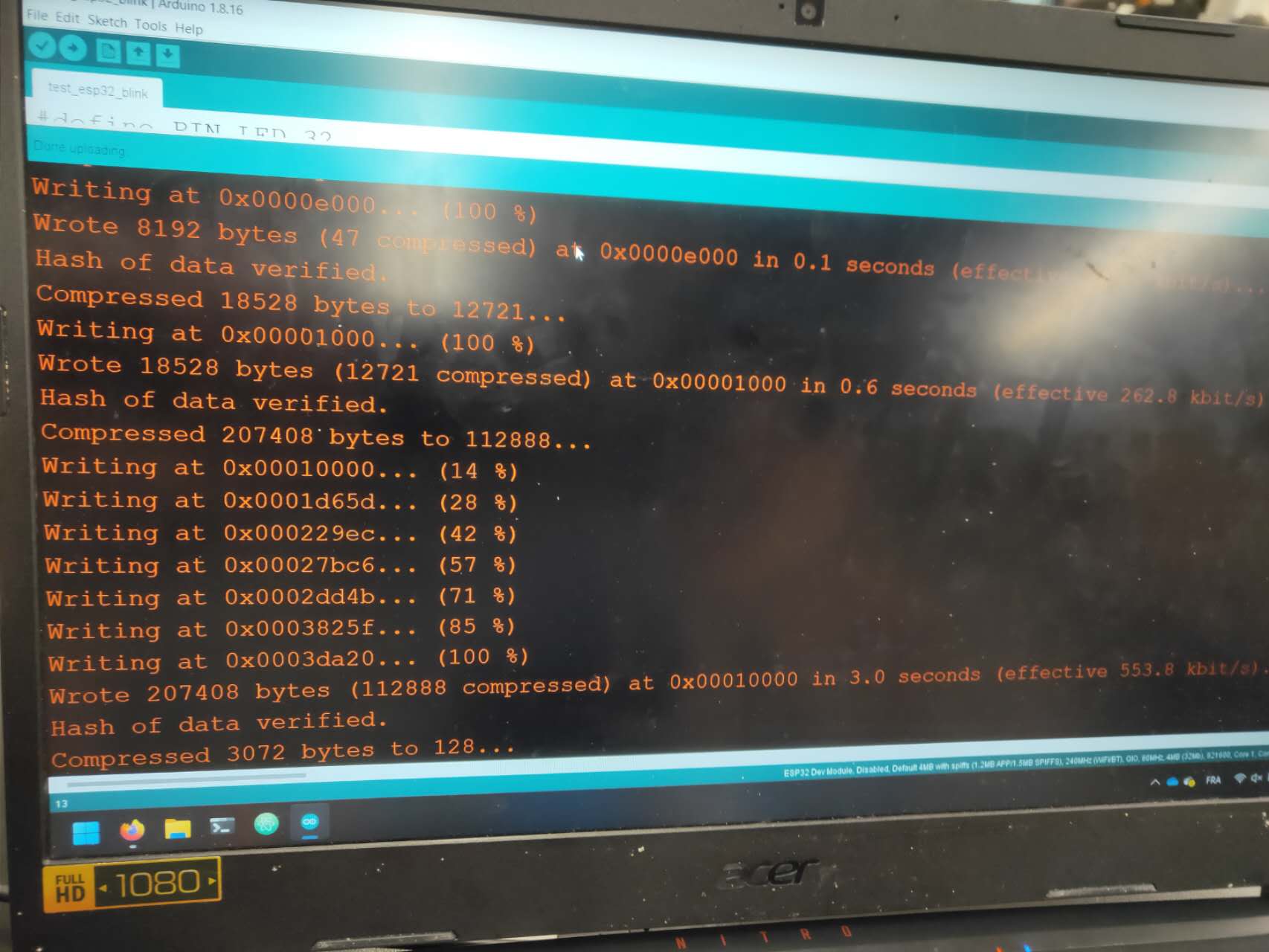
On Arduino, I added the esp profiles to the library, and I download the package in the library manager. After selecting it, my arduino is able to speak directly to the pcb and thus program it.
Making sure all the pins are connected and accurately according to the schematics. I also have to connect the devices to an open internet wifi, so the esp chip will be able to connect to the wifi directly. The controlling device with the web ui will have to be connected to the same open wifi with the esp chip.
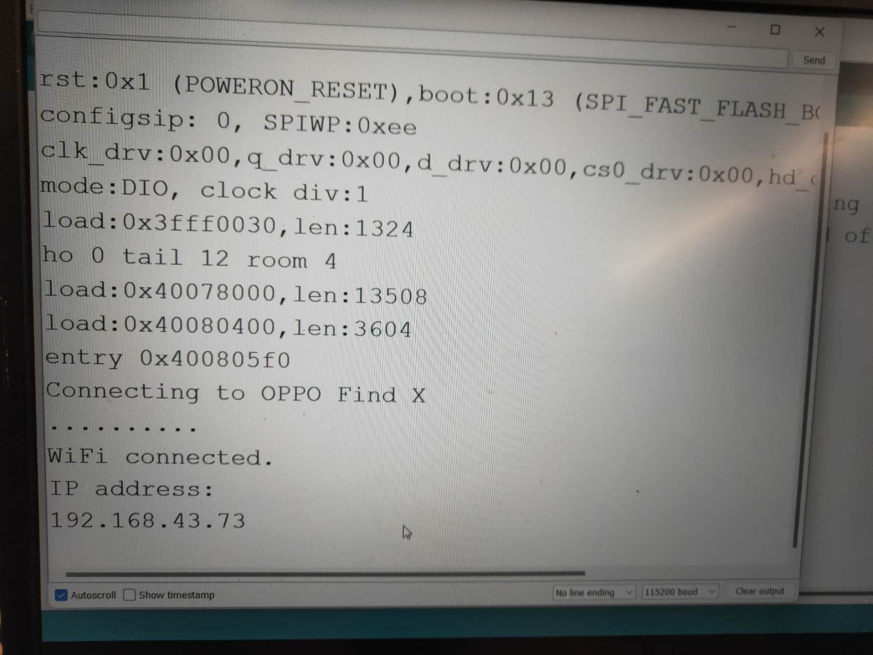
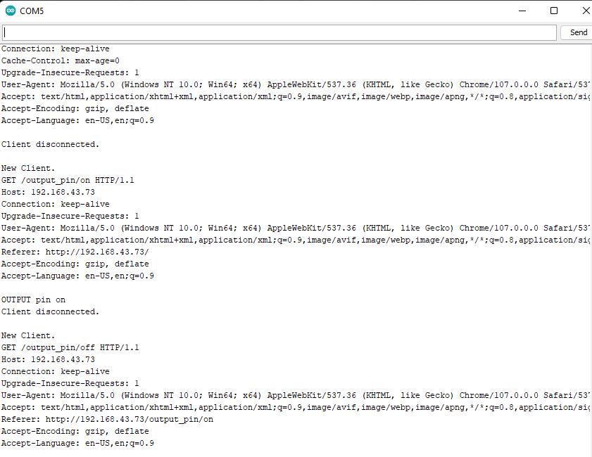
On the serial monitor, I am able to see the IP address after I hit the reset bottom on the esp pcb. By using the ip address, I am able to copy and paste this on to my other devices to open a web ui to control the esp to do certain tasks.
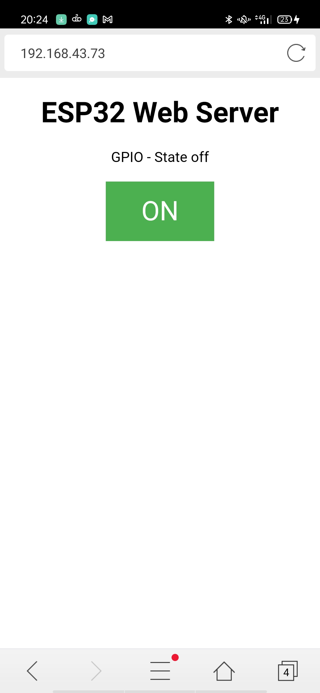
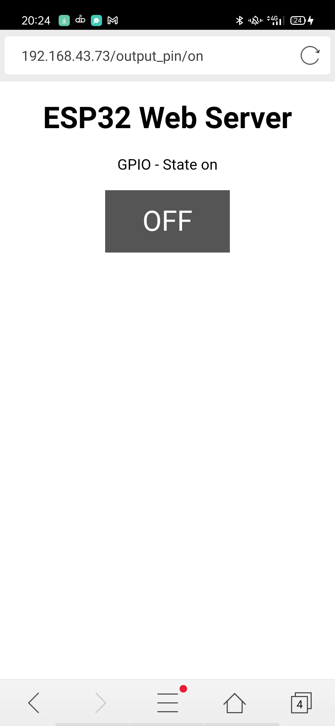
This is the web ui, which has a simple bottom to activate the code on the esp pcb. The board has a custom made LED on the pin32, which will turn on upon clicking the web ui bottom.
Here are the files for my pcb design.
Download Template Trace Download Template Outline