The fifth week we are tasked with designing our very own PCBs. We need to go through the process in electronics design softwares. I use fusion 360 to start. I decided to include a switch and a buttom on my pcb, each has a separate loop connecting to the processor. So, it will look like this: SAMD11 ->Switch -> GND. SAMD11 -> resisitor -> LED -> GND. By doing this I will not turn on and off the LED with the switch with direct current, but with actual programming.
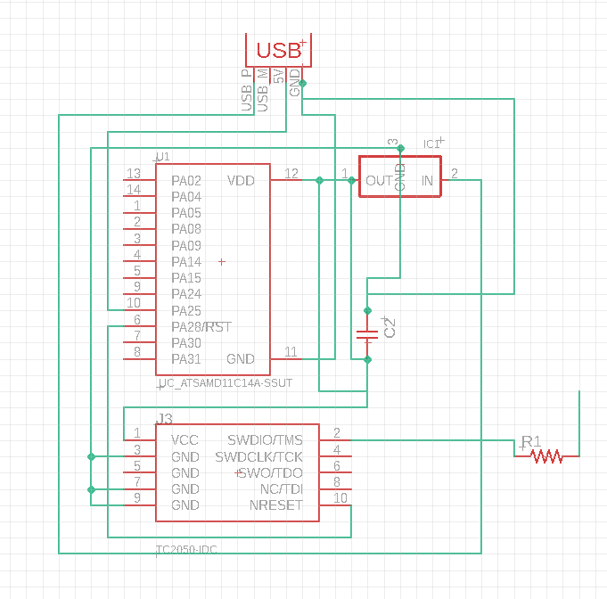
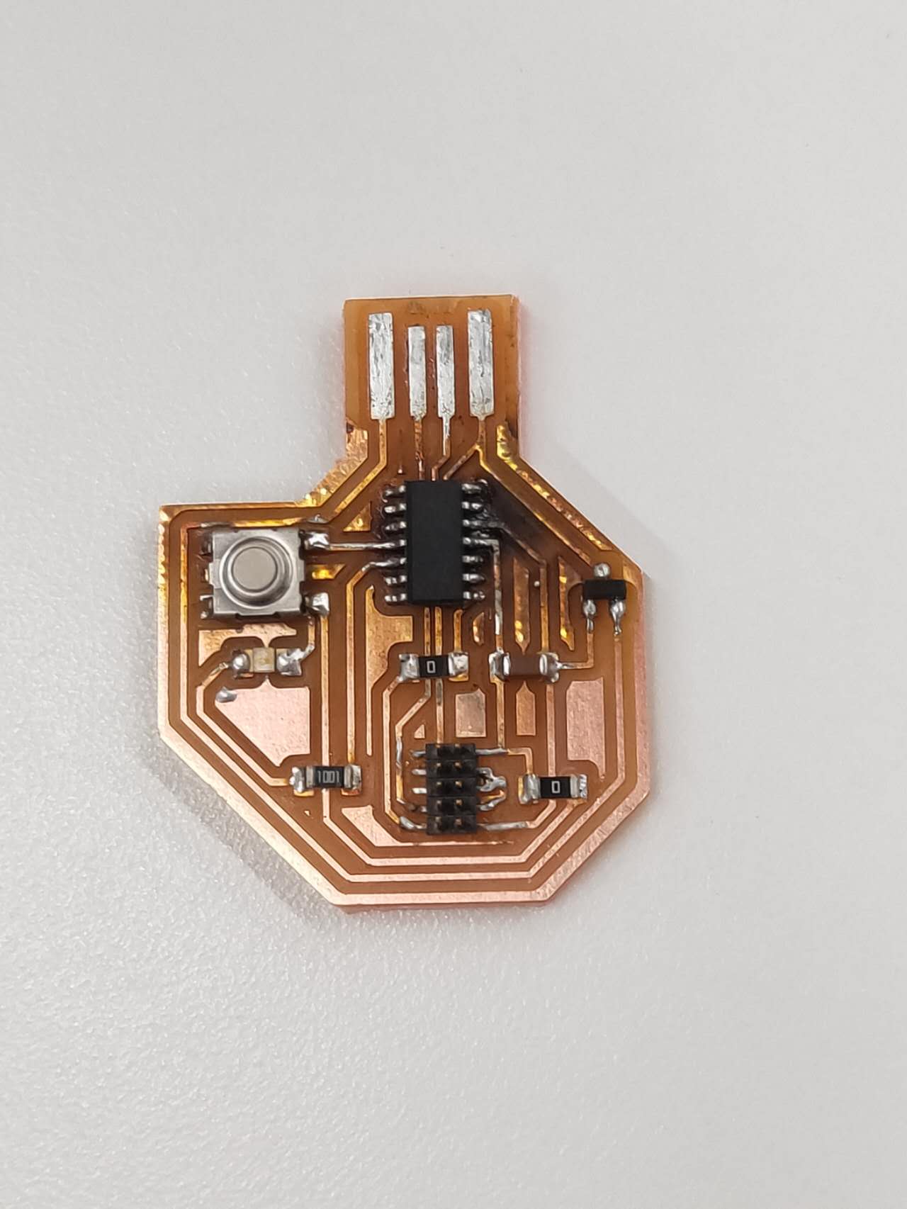
I start off to plan what I need on the drafting sheet. I begin to understand some pattern in electronics making. The USB connector has 4 copper pins, each represent a different function. First pin from left is a USB p which goes into PA25 , second pin is USB M, which goes to PA24, third pin is the 5 V power, which needs to go to a regulator to turn to 3.3v in order for processor to run, and then it goes into a capacitator. The 5by2 is a connector head which connects itself to the processor and the ground in order to receive information from a bootloader.
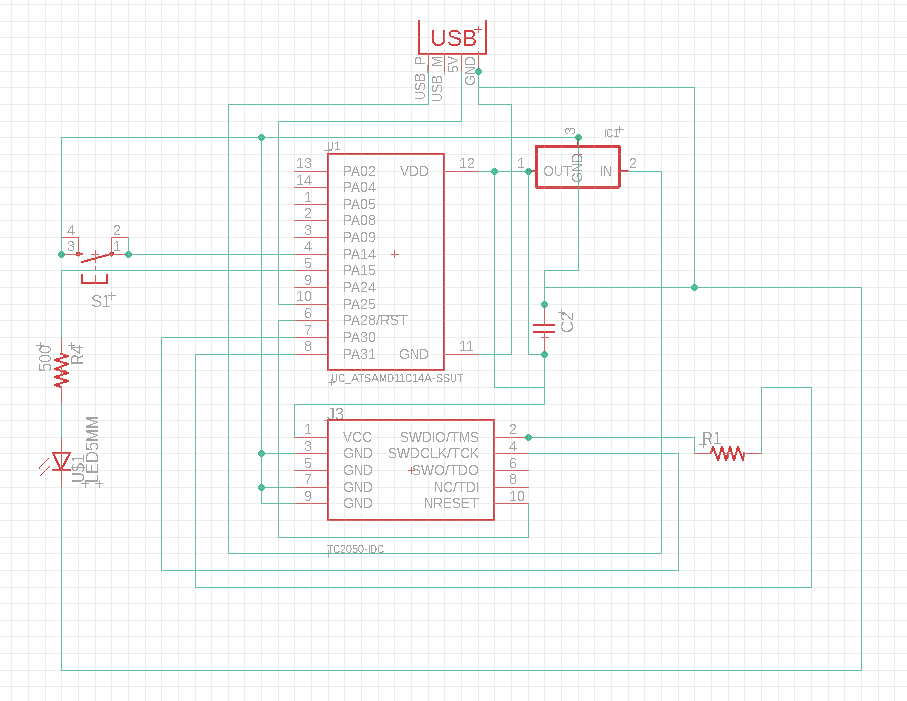
I have to add 2 more 0 owv resistors in the schematics in order to jump my current on the 1 layer copper board. I can create a loop in the draft and thus it can act as a bridge to go across other currents.
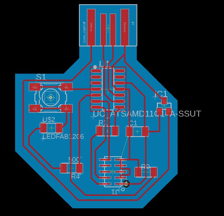
Here is the layout of the components. I need to make sure I set the trace to 10. The default was 6 and it is way too skinny. 10 is more sufficient. Also we need to make sure in rules, make all the offsets 16. I use the "display off" "display on" commands to export pngs from the layout, which I set the DPI to 800 so it is very clear for the mail software to pick up the outlines.

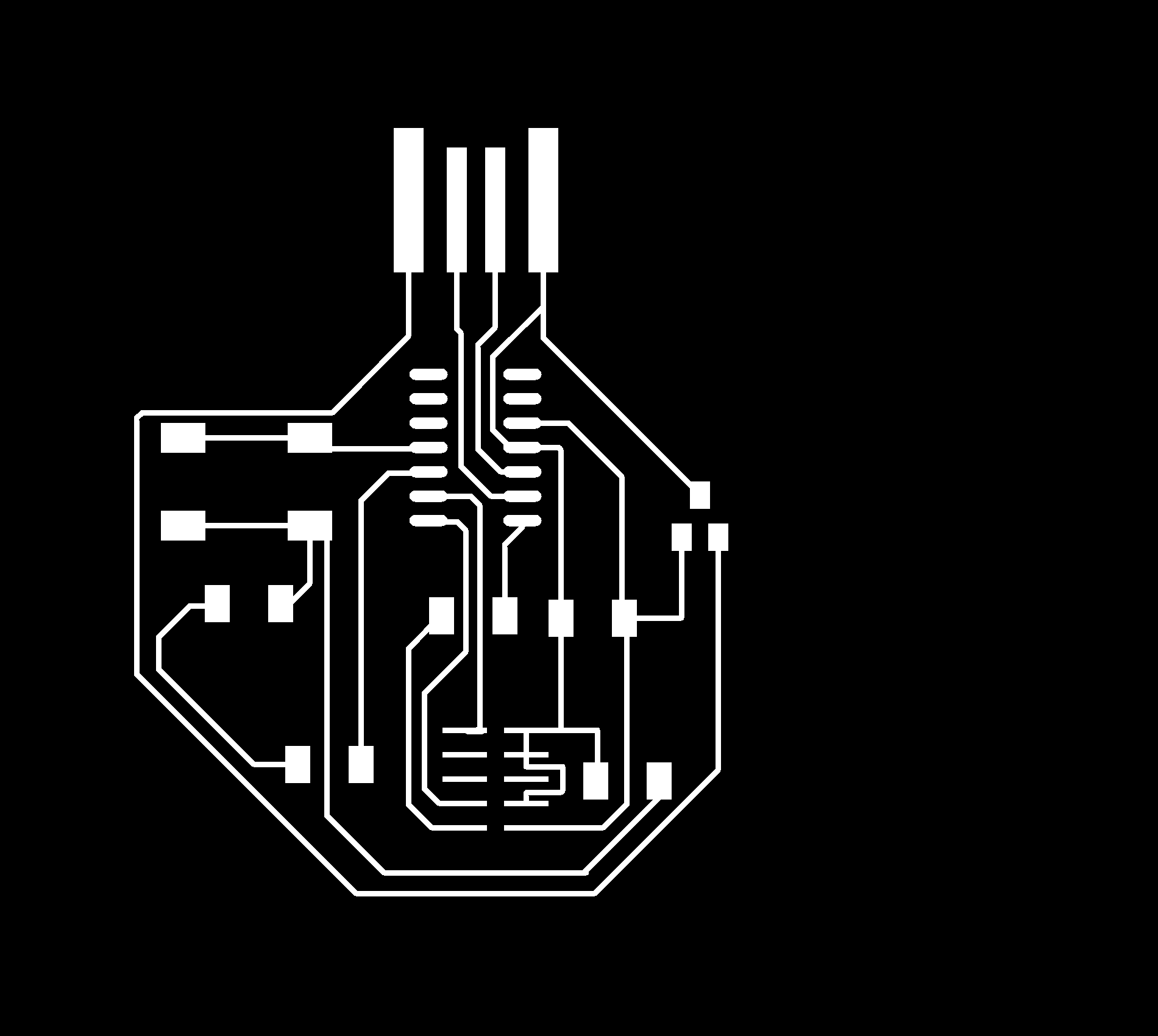
Here are the two pngs, one with the tracings and another with only the cut outline. I didn't go too fancy with this one because I have too much to learn. I want to practice first.
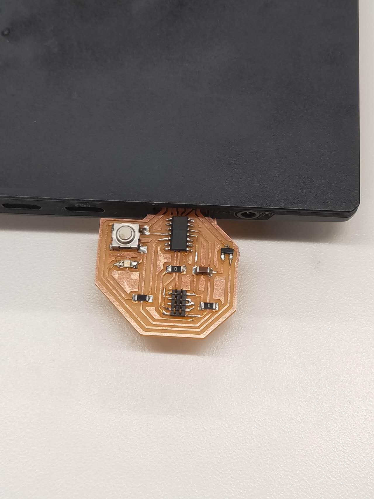
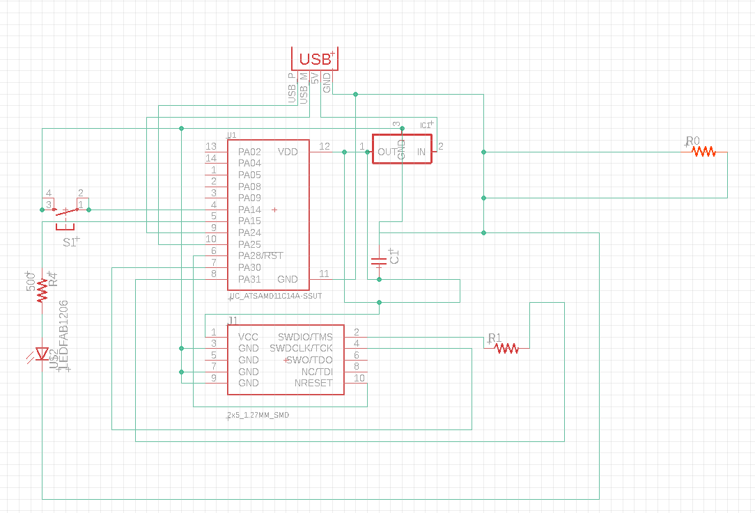
I soldered on all the components and bootload the chip, it worked. However, the TA helped me to load a program in it and it didn't work. Turns out that there is a short since the copper trace of the 5V touches directly with the processor. Hence the SAMD11 got burned out in the process. I also need a lower resistor since I put a 500k resistor initially. It is too much which makes too little current for the LED.
I removed the processor and tried again. I failed again. Then I tried again. The chip now is burned because I blow too much hot air on it. I also have to use a knife to manually separate the copper trace from touching each other. (upper left)

Here is a simple arduino script my TA wrote for me. It is simple. Upon pressing the buttom, the LED will flash and will send a message to the computer that it has plugged in
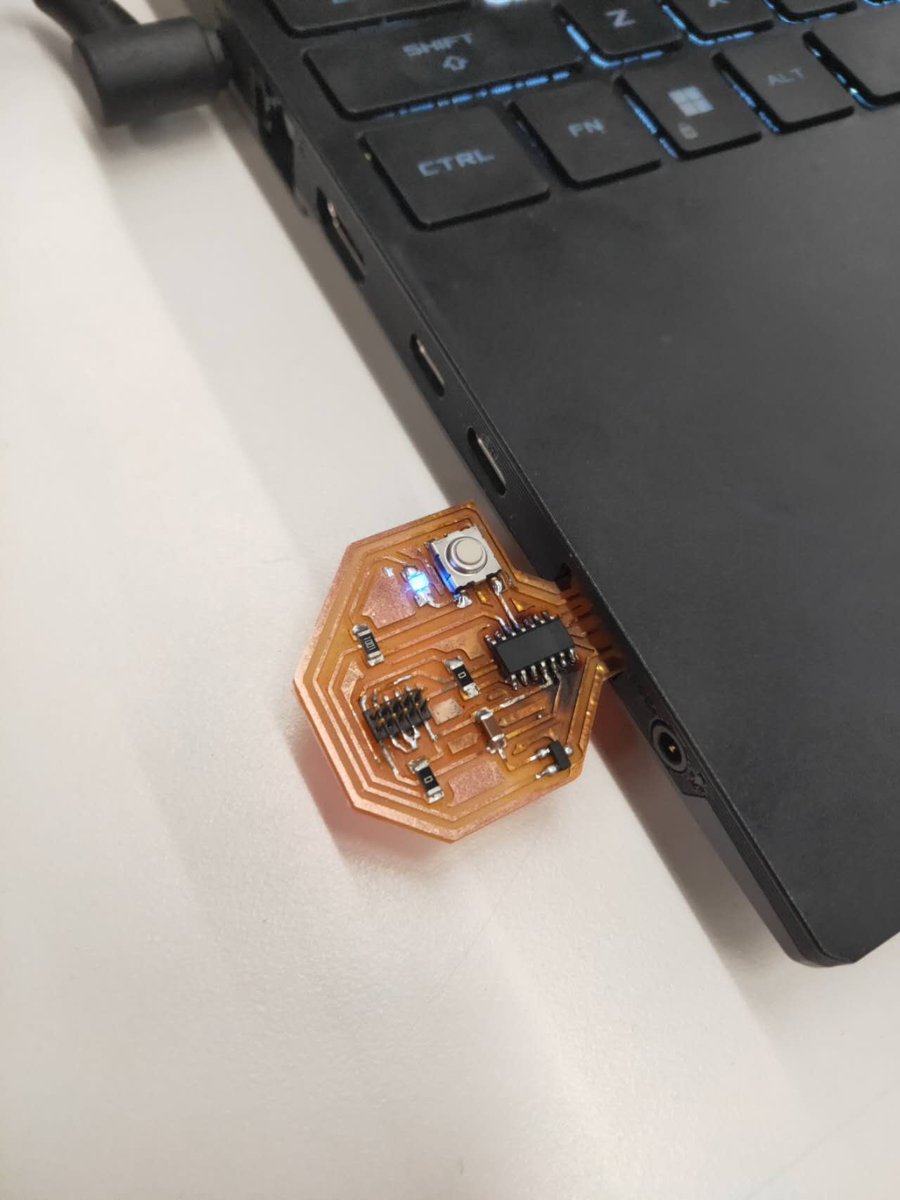
Here it is flashing the blue LED light! So much to learn, both PCB and Arduino
Here is the link to download the png pattern to cut your pcb!
Download Template 1 Download Template 2