
This week’s assignment was add an output device to a microcontroller board you've designed, and program it to do something... ANYTHING!
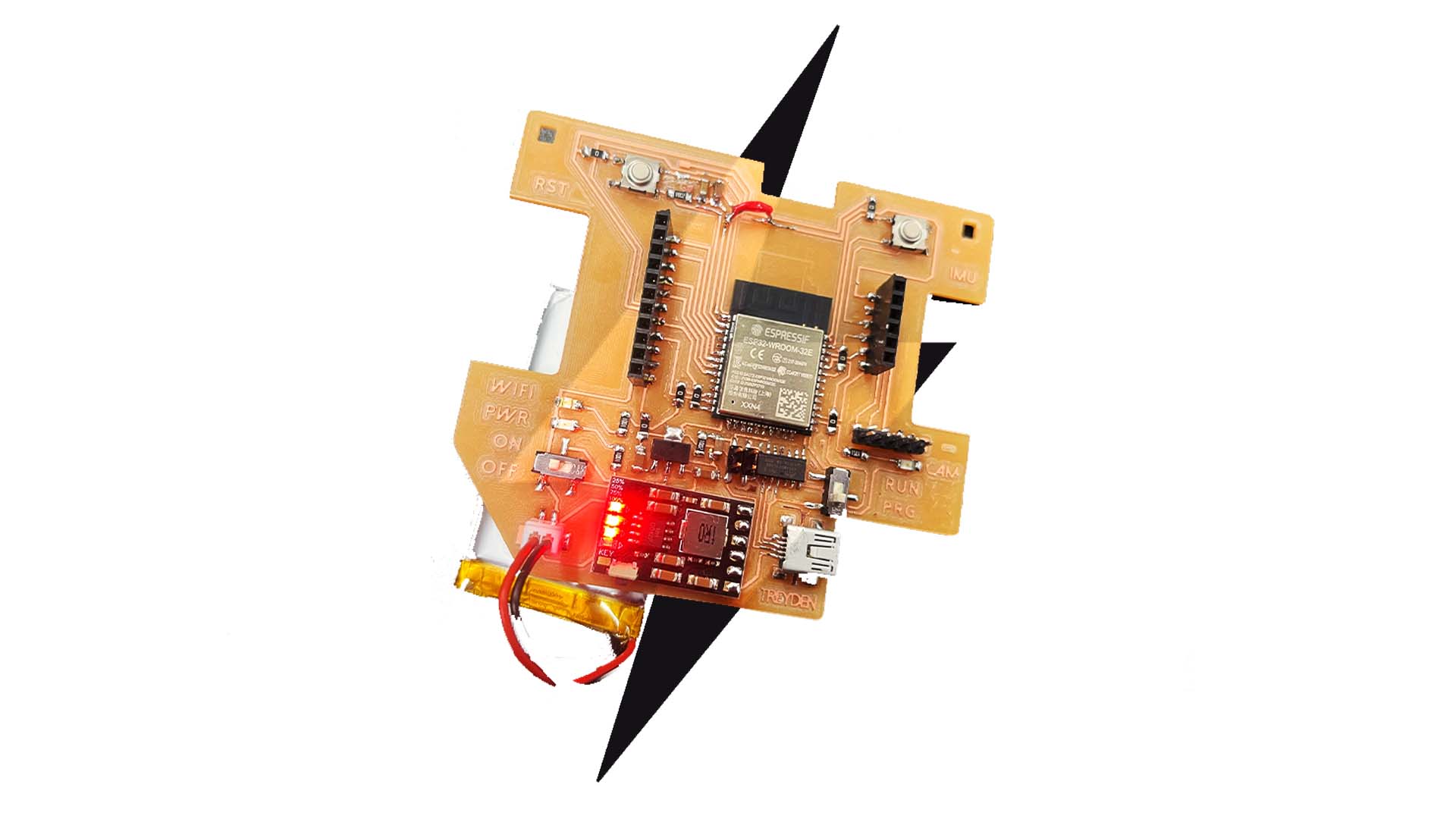
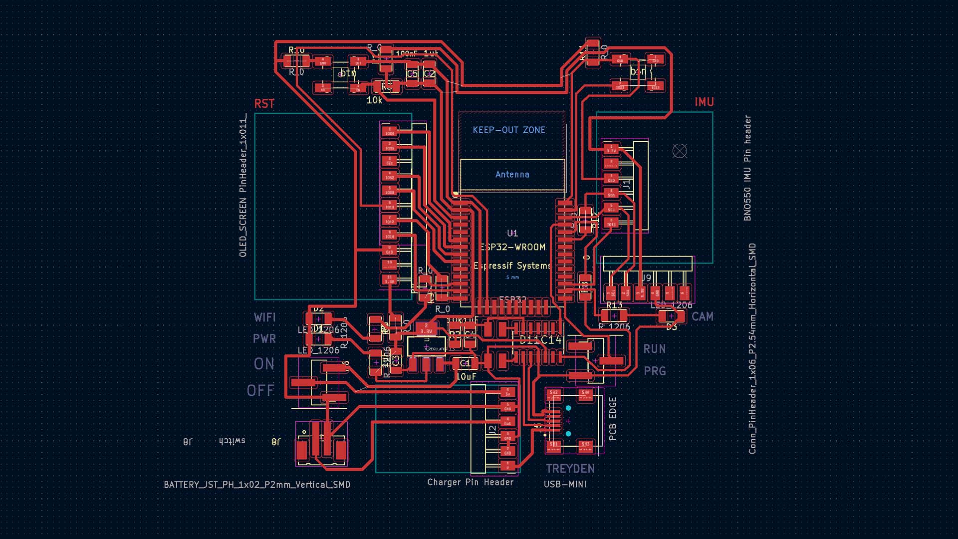
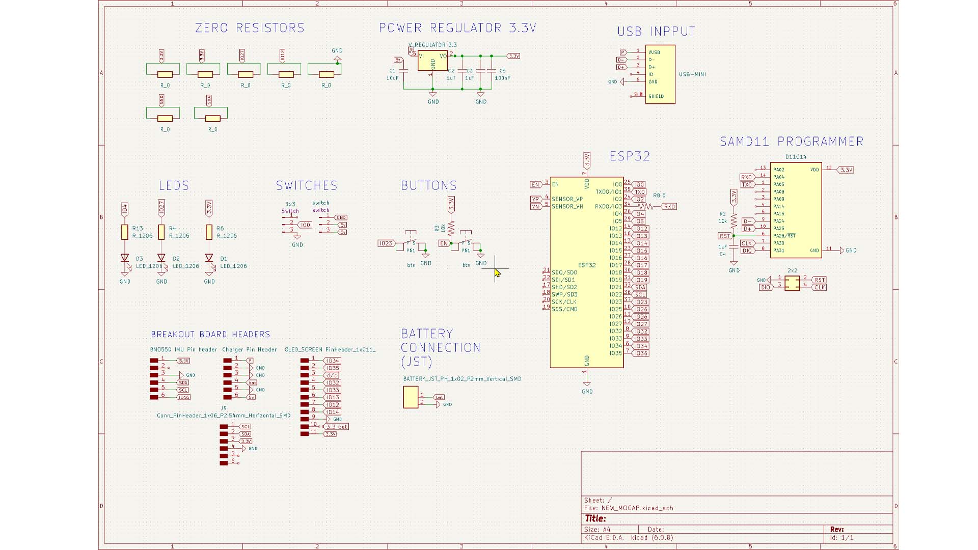
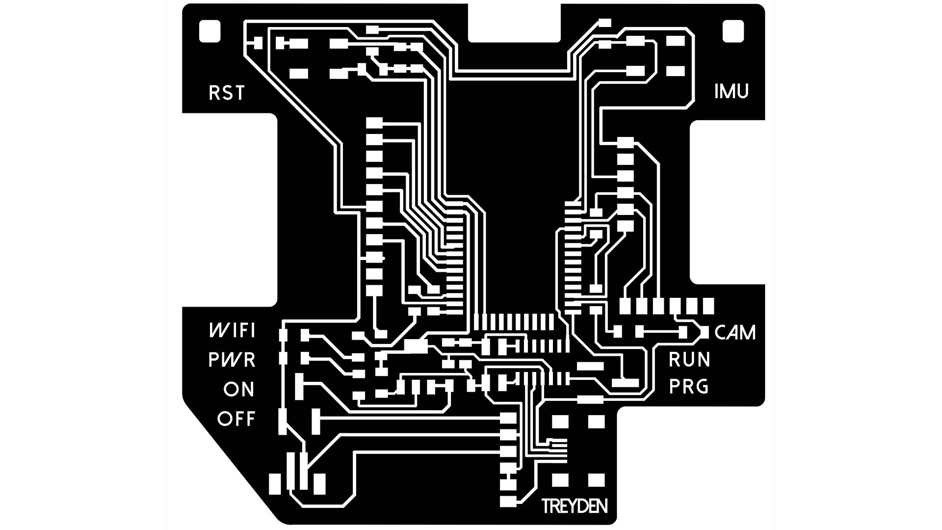
My plan was to add a battery to my previous PCB design along with an OLED screen, more specifically the TFT adafruit breakout board. I went back into my Kicad file from week 7 and basically restarted the layout, adding many new components to satisfy all of the requirements for the various attachments to the ESP32
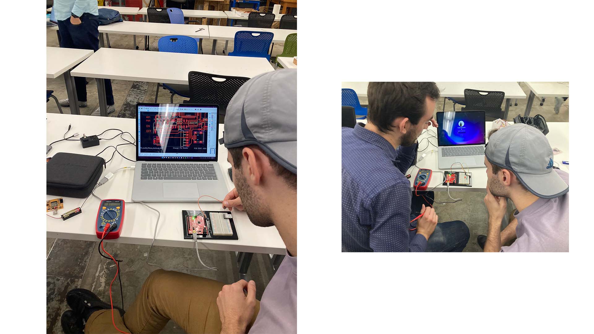
I wanted to add switch to the battery so that I could turn the device on and off with the battery still attached. Quentin helped me determine how much power the Buck Booster would pull from the battery even if the device is turned OFF. We did this using an arduino and a multimeter.
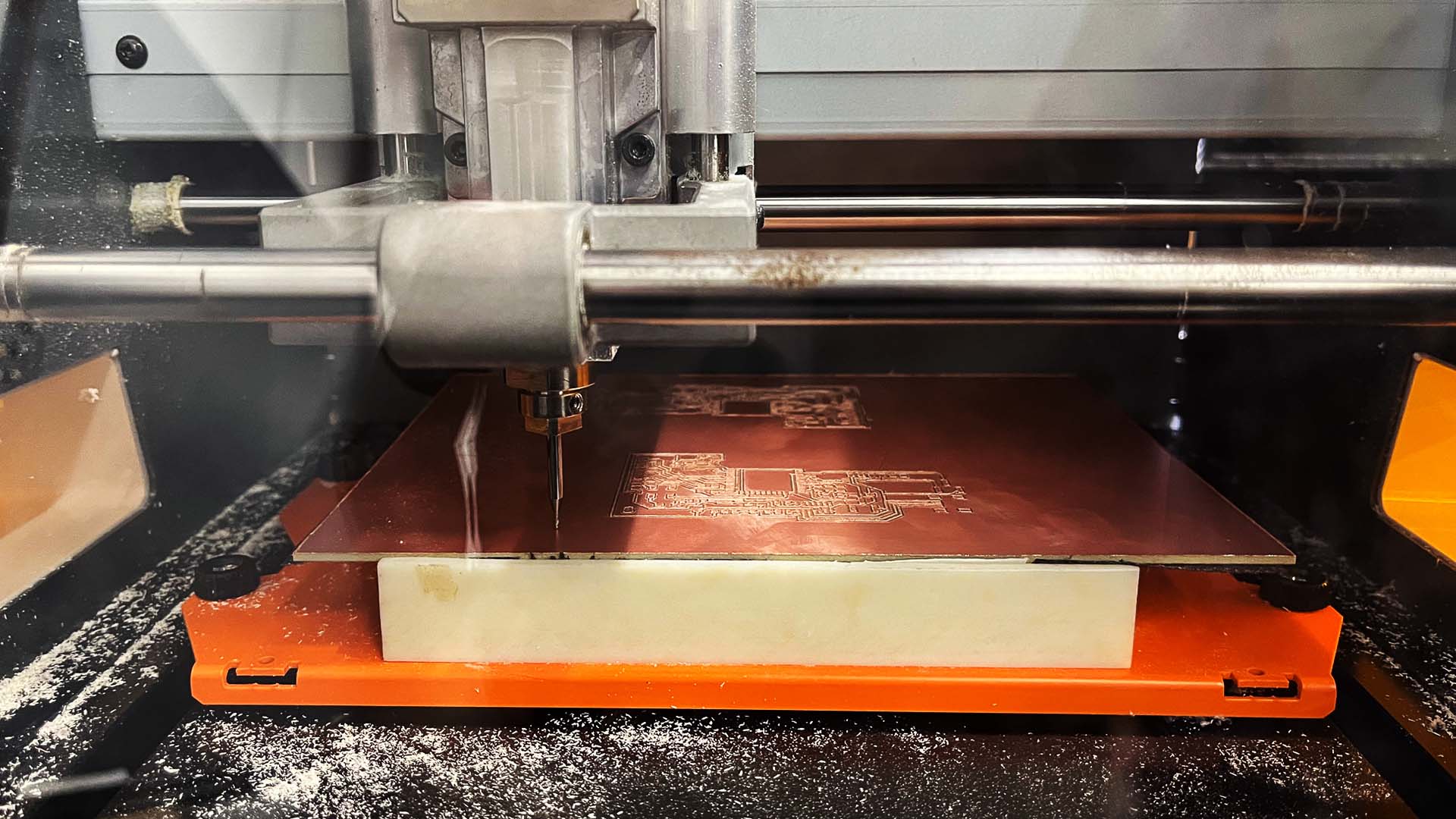
After I exported the files as PNGs from Kicad, with some additional revisions in Photoshop, I used MODs to cut the board out from the copper layer. This task ws much more difficult than I had hoped! On my first two attempts the tape gave out during my outline pass and I had to start the boards again for scratch. They each take about 4 hours!
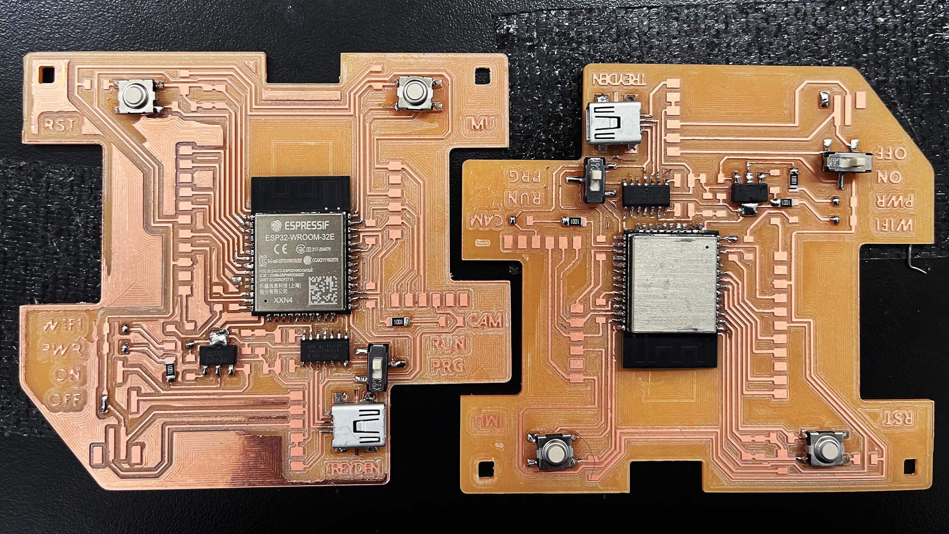
Next, I went on to soldering which, I believe is the peaceful part of the process. Although, there were some difficulties as the milling machine didn't completely remove all the copper off in an area I needed. Therefore, I went at the board with an knife to remove these sections and inevitably I cut a trace in the process.
Although, attaching the components is not the task that worries me. My concern is whether or not my design with be able to be programmed!
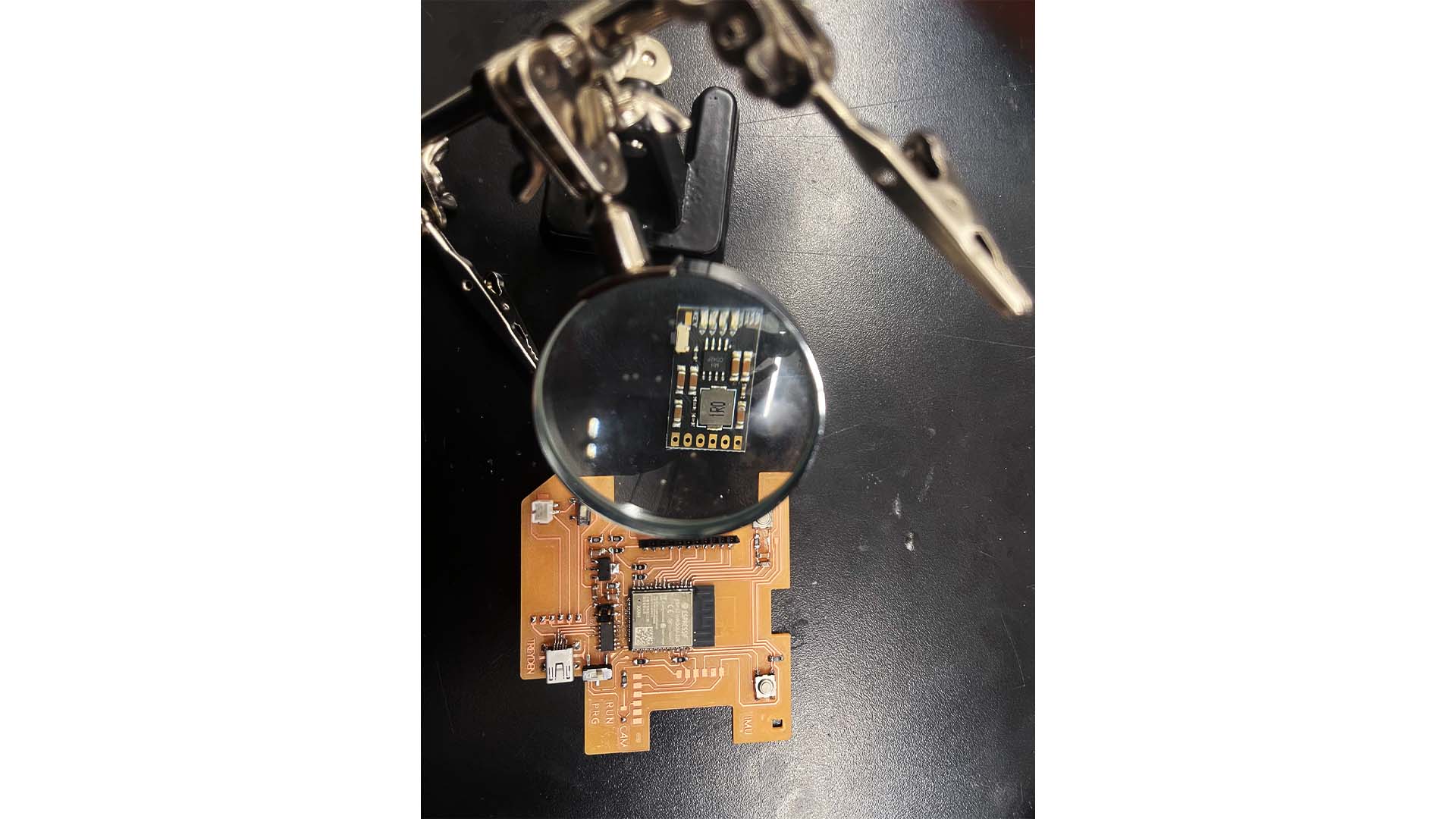
I wanted the buck boost charger for my Lithium Battery to lay flat on my PCB. I tried this technique of place the solder down first and heating the solder underneath the breakout. But, this turned out not to be successful. Luckily, with a new soldering iron tip, I was able to put solder down through the pin holes from above with relative ease.
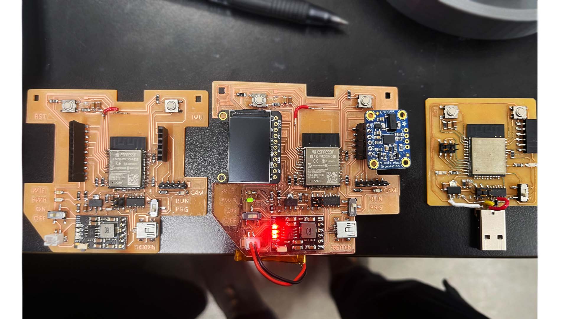
Lastly, I needed to install and burn Openocd with the VCP bin onto my finished PCBs. This required a PCB already programmed to be a bootloader. Of course, I have one from week 2, but for this board I needed a 2x2 pin headed board which I could not find in our lab. Instead, I tried to connect the two boards through a 2x5 pin head connector with wires to attached the correct pinouts. Unfortunately, I when I ran Openocd on my computer I could not get a connection between the two boards! In a previous week I tried to mill a convertor board for 2x5 to 2x2 but this milling job failed. Since I will be using these 2x2 pin headers from now on I decided it was time to mill my own 2x2 programmer.
More work to come in milling a 2x2 pin bootloader...

As a group, we were assigned to measure the power consumption of an output device.