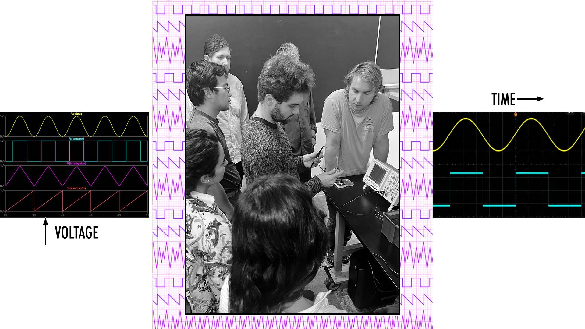
This week’s GROUP assignment was to use the test equipment in your lab to observe the operation of a microcontroller circuit board. Our task was to learn how to uses the tools for chekcing the signals of your PCB and more generally learn what the currents of your program look like once your baord is functional.
Working with the entire Harvard Section, we used the Oscilliscope to look at the signals producing the audio in a open source video game PCB our TA Leo designed. We determined that different wave funtion according to your code appear differently through the Oscilloscope. Our machine had to be calibrated to the correct scale to be able to see the amplitude of the wave forms with more accuracy.
Individually, we were assigned to design a Hello-World board with atleast a button and LED. We were tasked to check the design rules to impliment through our software of choice to create PNG files that would milled correctly.
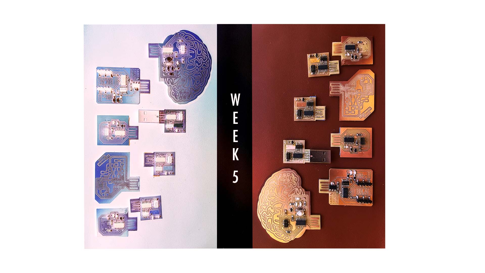
I used Fusion Eagle to model my PCB starting with a simple Hello World echo board with an LED. IN a circular production process I planned to start small and work my way up to designingthe board of my dreams. Next, I milled my design which can with several hours of trouble shooting. The CNC Mill get me lots of trouble as I was having difficulty with the bed being unlevel. Therefore, I tried to find a way to replace the sacrifical layer to no avail. I learned to play my design in a specific location on the bed which had the strongest contact with the end mill but need to trouble shoot this problem further. After milling two copies of the boards I moved on to Soldering which was undoubtedly the easiest part of the process. Programming the board was a bit of an issue because I realized after milling my traces were extremely thin. For one 0of the two boards I created the pin headers and copper traces pulled completely off in the process of programming them. I successfully programmed the one board dispite these issues but realized I also connectd my LED to an analog pin. At this point I when back to eagle for a redesign.
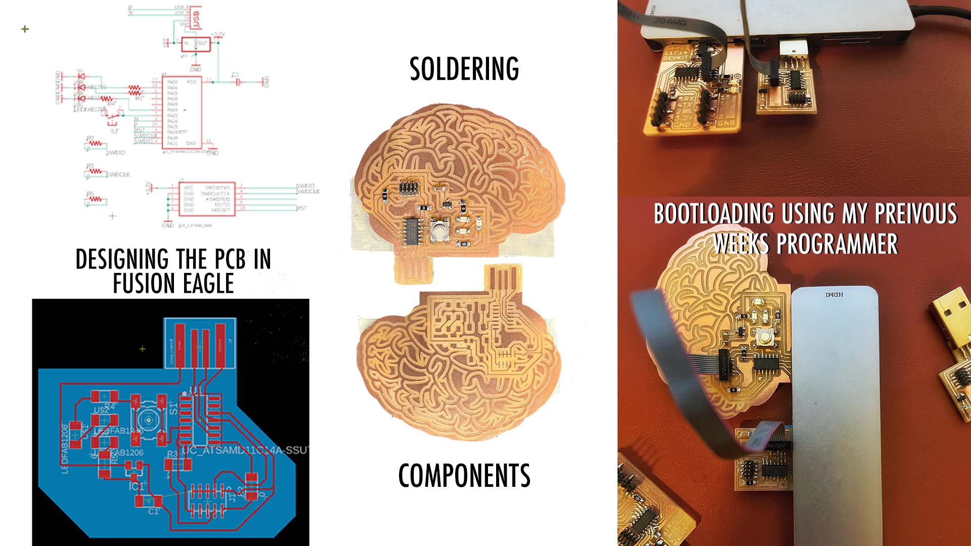
My goal was to get more creative with the shape of the board and add a button to the PCB. Working with Eagle wasnt always a smooth process but as time went on promise you it gets easier. I added multiple LED this time around and a button that would be able to activate them. Milling with this machine continued to give me issues but I was able to overcome them with a similar procedure as before.
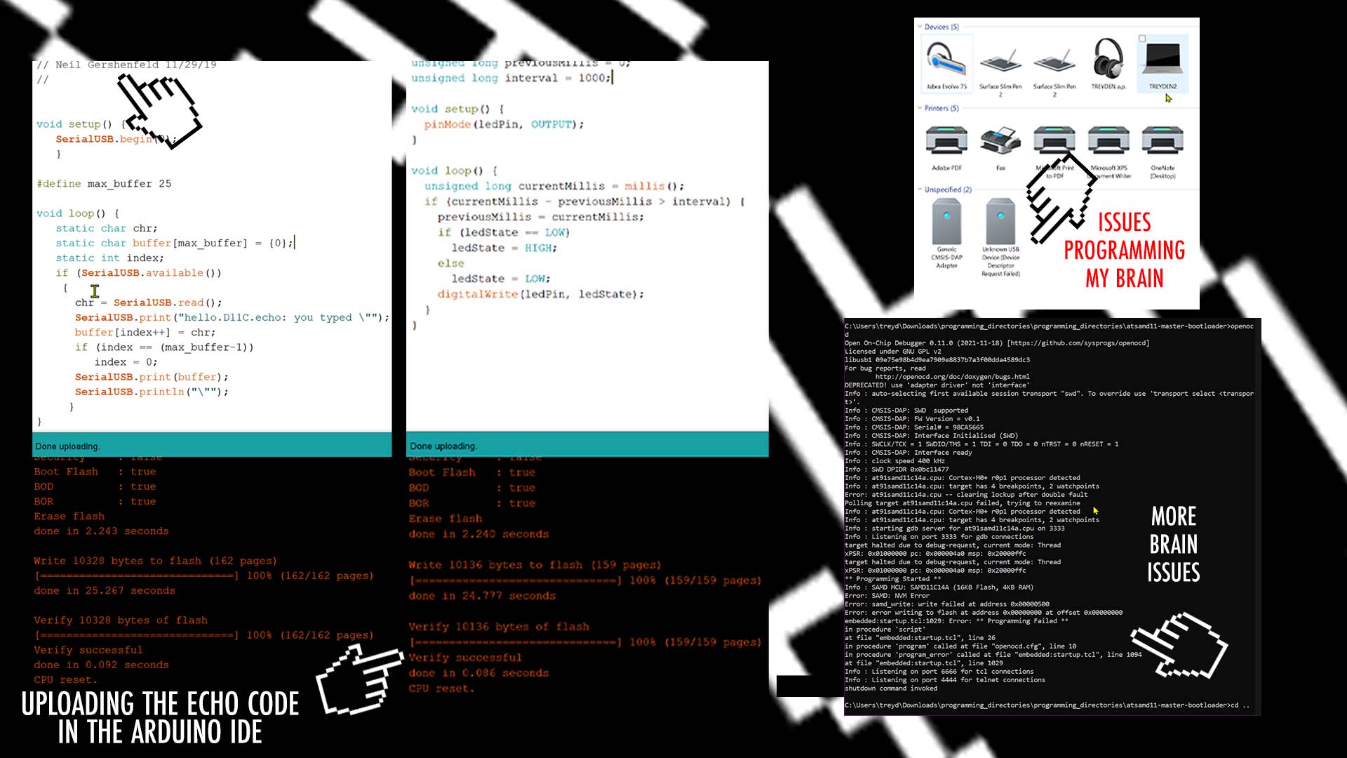
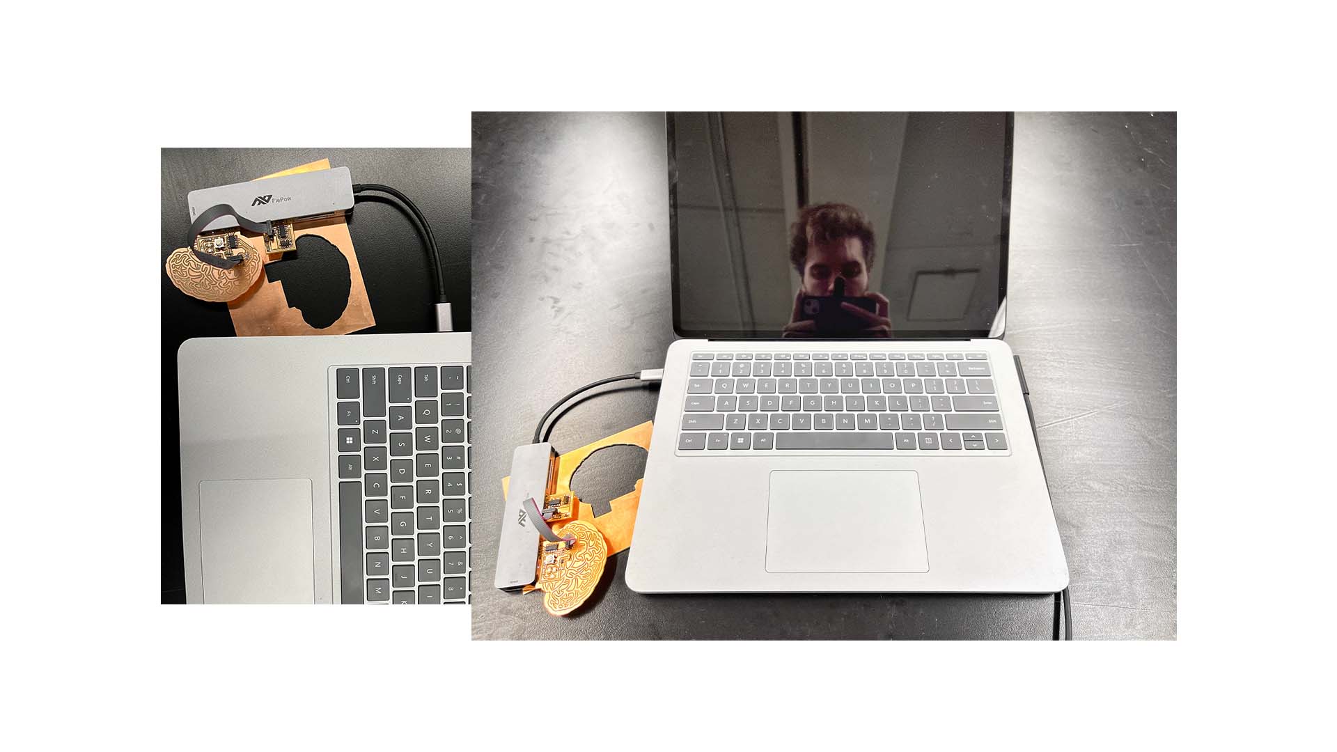
Lastly, after creating my 3rd 4th and 5th baord I ran into isues programming them again. This time I worked with the TAs and it was not clear what the problem was. I soldered on a new processor and other components but had no luck gettting my board to be recognized by my computer properly. Unfortunately, many of my classmates needed the Milling machine at this point so I wasnt able to reprint my traces but this is my next step for successfully getting my design to work.
Although, none of my boards were a complete success I am confident I will be able to create a fully funtional board in the next couple of days
I plan on taking a deeper dive into learning the ins and outs of electronics to have a greater understanding of how my processors and components can work together optimally.