Electronics Production
Group Assignment - 09/24/2022
Build In-circuit Programmer - 09/24/2022
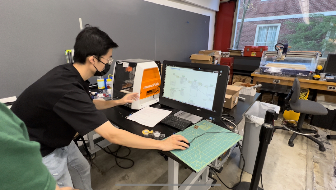
I followed these steps (similar to the vinylcutter):
- double-taped the board on the white sacrificial layer
- import the trace PNG files to
start mods - Select
...traceandcalculate - Change the drill bit to
1/64(thinner), selectmove to origin - Wait for 5 sec (otherwise, we need to restart the machine) and open the lid, make the drill bit touch the board
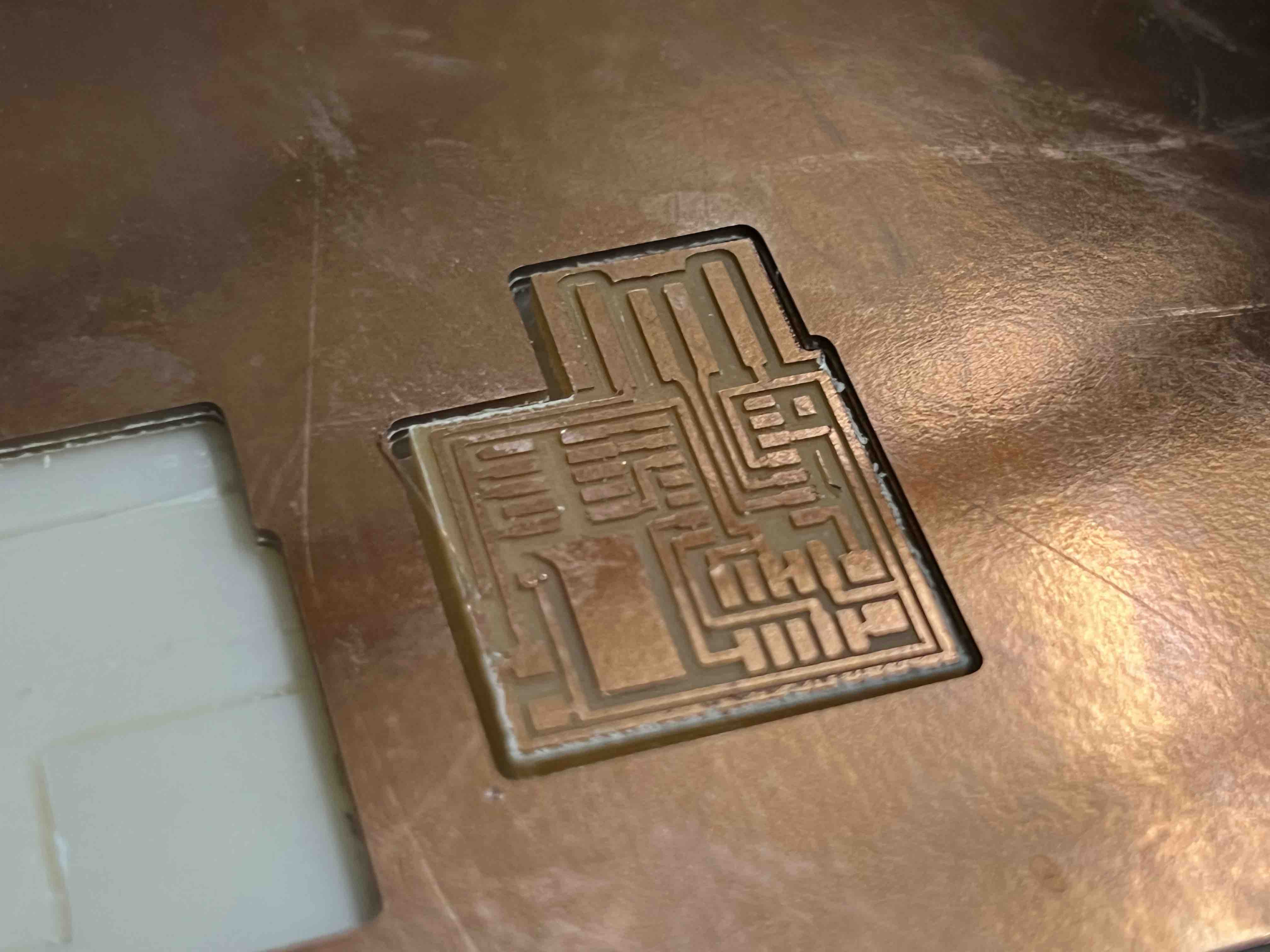
- Send the file to the device (the drill bit will do each trace 4 times, so it takes about 10mins)
- After it's done, open the lid, vacuum-clean the debris (Remember to press the board you want, otherwise, it might be sucked into the vacuum.)
- Change the bit to
1/32(thicker), do the 3 with...outlineand 4,5,6 steps. They will cut the board out.
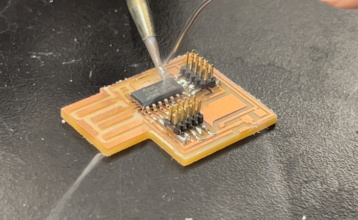
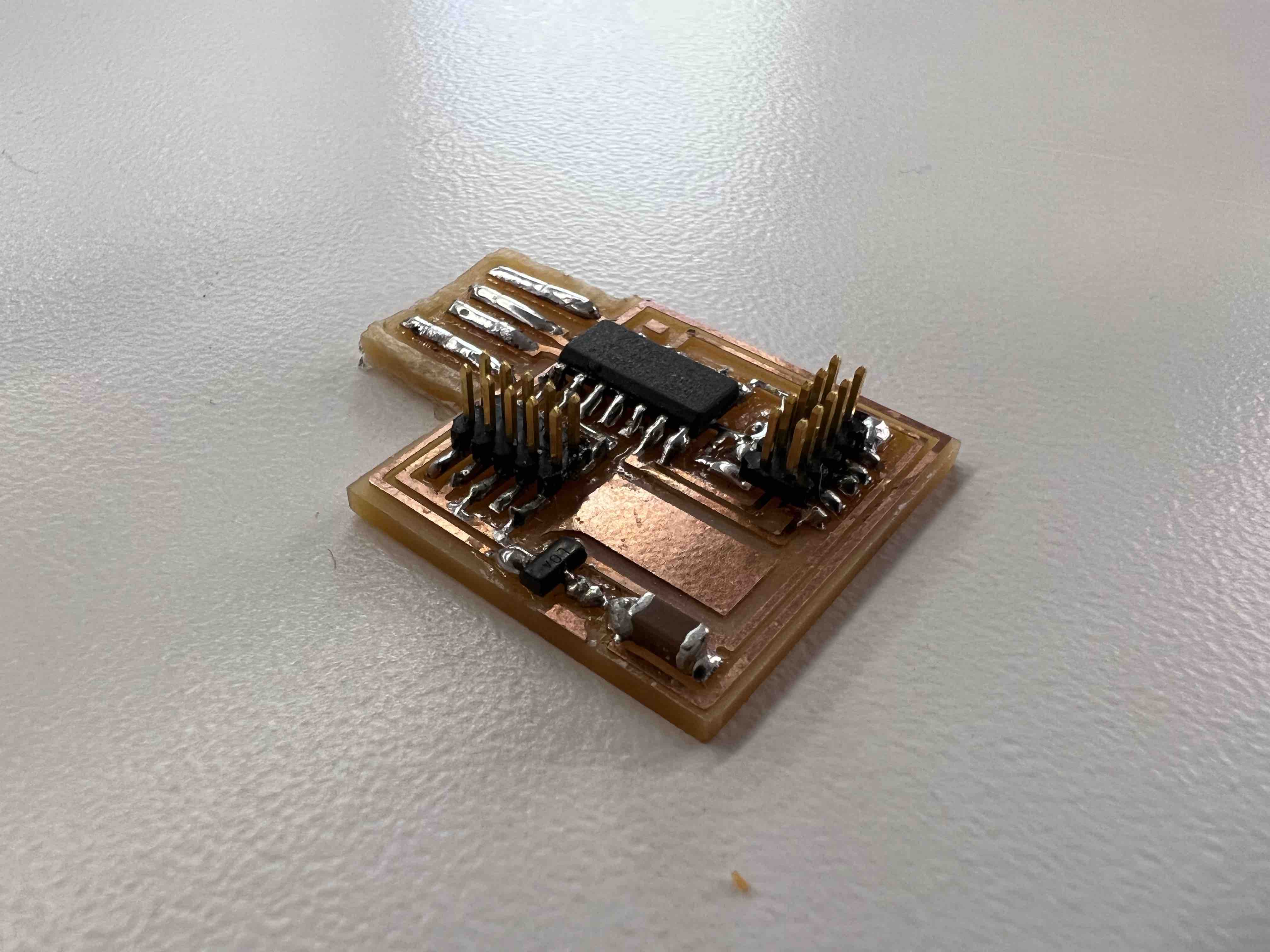
I used wire solder (we couldn't find the paste), I noticed a good practice was to make sure the copper part is a bit longer than the pin of the component, in that case, we can put the tip of the gun on the corner formed by the copper and the tip, then touch the solder at that corner.
Oh, also, someone told me to solder the pin of the USB port (so they bump up) and also remove the outskirts of the USB port
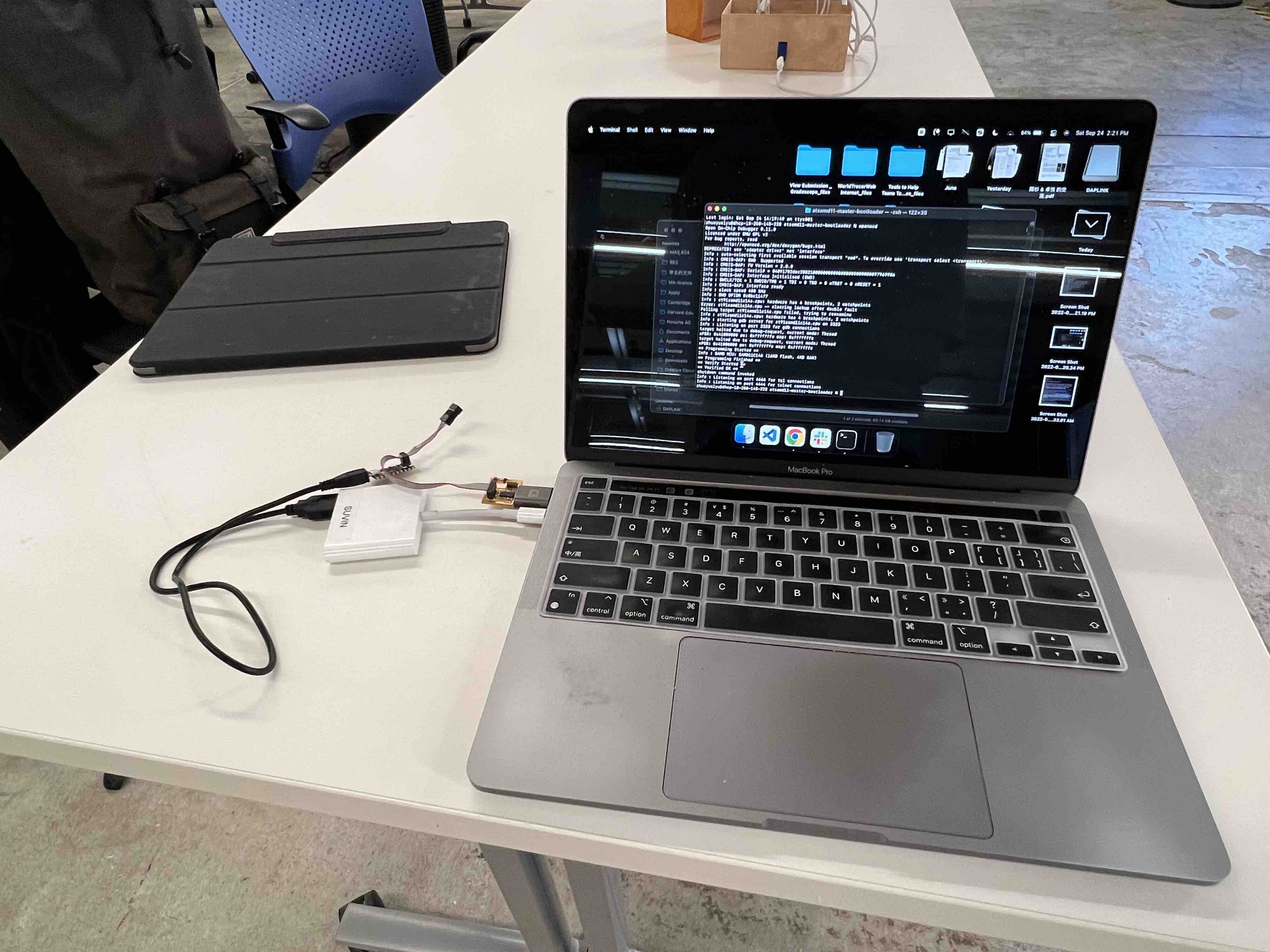
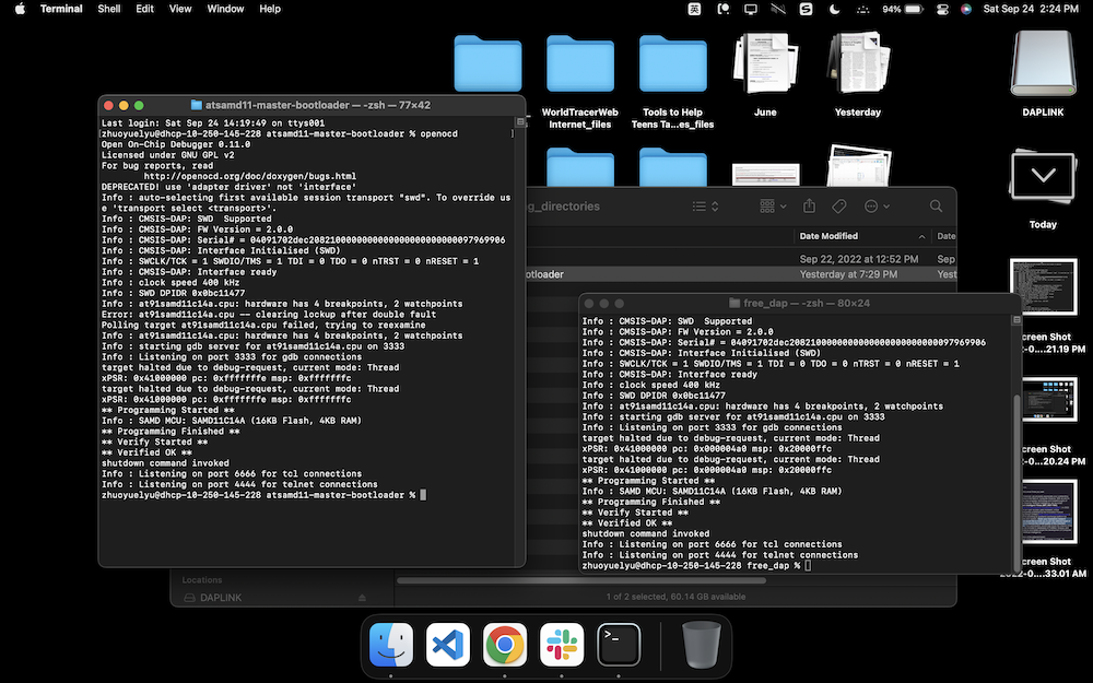
Finally, to program the board, I used the board provided by Suvin to program mine. Several points to pay attention to:
- Make sure the board to be programmed is connected on the back, the board as a programmer is connected on the side
- Do
openocdonatsamd11-master-bootloaderfirst, then onfree_dap - When we see the
Verified...OKstuff on both folder, that means it was successful, we can now use this board to program others' board.