Machines Week
Kevin McCallister Toilet Paper Launcher, Marble Trapping Mechanisms, and overall speaking - machine mayhem
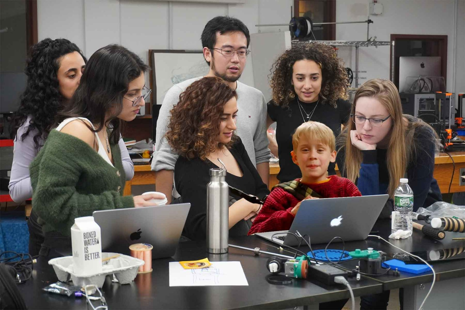
Machines week. We knew this week would come, but could we have been prepared what was yet to happen? No.
Ideation
We met as a group on Thursday morning to brainstorm machine concepts. Here’s the blue-sky list we ended up with: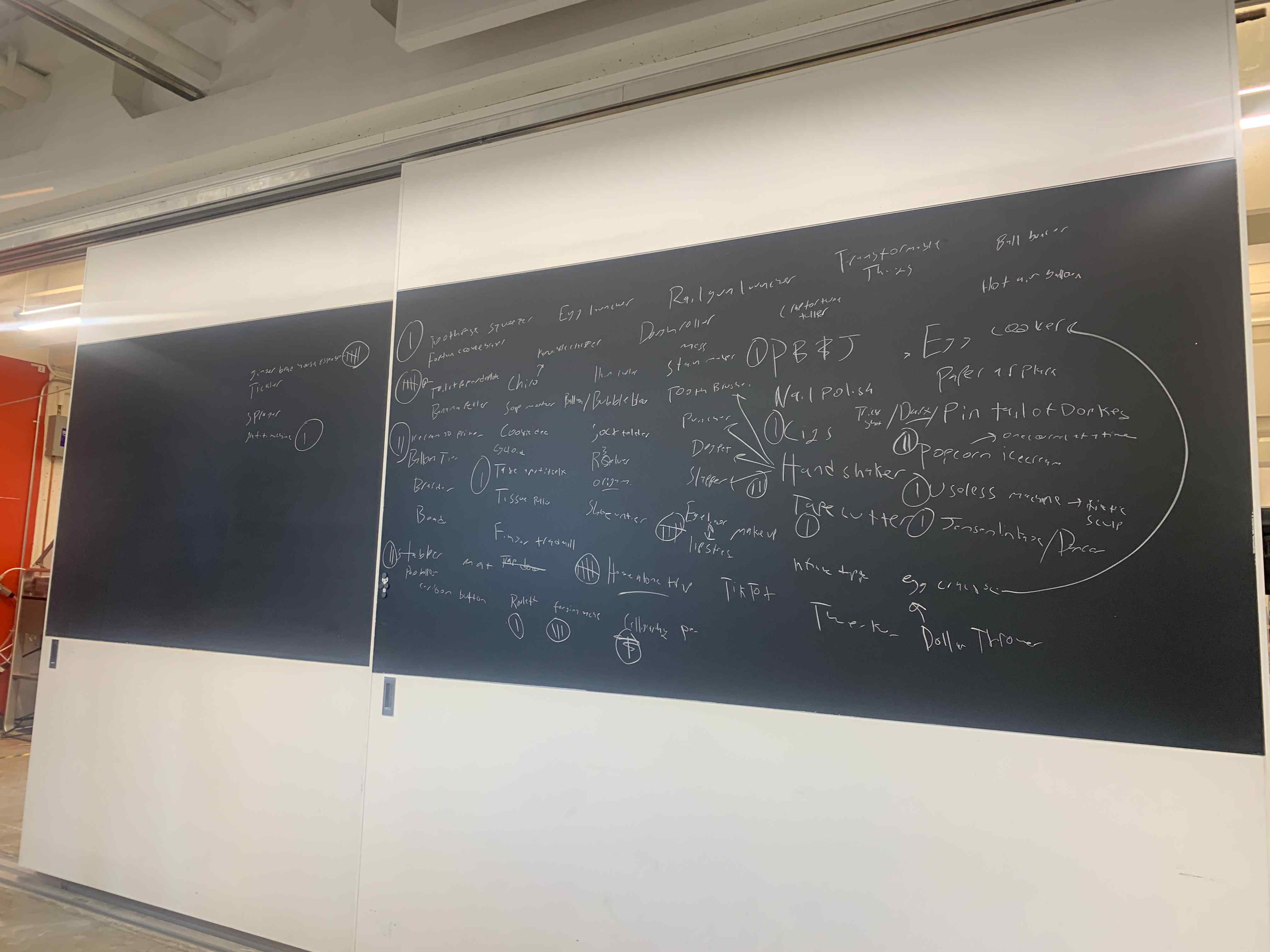
We then gave everyone in attendance three votes for their favorites. Top candidates after this were:
- Gingerbread-house-maker
- Toilet-paper-launcher
- Makeup-applier
- Handshaker/stabber
- Forger (not related to Jessica's extracurricular activities)
Then, we talked through logistics for each finalist before voting again on our favorite. The toilet-paper-launcher won by a significant majority, and we resolved to add some additional boobytraps inspired by Home Alone if spirals allowed.
Dividing to Conquer
Next, we split up into teams to tackle each sub-component of our larger system, plus logistical support.- Photographer / videographer: Nix
- Video editing: Alexia
- Software: Caine, etc. etc.
- Dispenser/unspooler: Claire, Noy, Rehana, Selin, Sondos
- Aimer: Danny
Dispensing Team
Engineering a dispensing mechanism - Day 1
We started out by comparing several different options for launching mechanisms:- air
- motorized feeder wheels, and
- combination of the two.
Claire suggested a motorized feeder wheel and follower to unspool the paper and hopefully throw it forward at the same time.
Selin found a video of a toilet paper unspooler (and folder!) where the toilet paper roll itself was motorized to spin. Nathan was an advocate for this last idea.
First, we decided to experiment with an air-powered system where we would build our own fan using a motor from the shop, 3D printing our blades, and creating our casing. For proof of concept, we hooked up one of the soldering airguns to test its airflow… and quickly discovered it was nowhere near powerful enough.
Some googling revealed that leaf blowers typically move air at 90-250mph. There was no way we were going to achieve comparable speeds with the motor we had.
Meanwhile, Nathan sent a message in the Slack suggesting a feeder wheel and follower similar to Claire’s but in reverse (with the feeder wheel on the bottom and the follower on top).
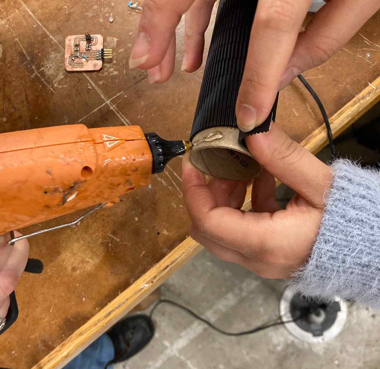
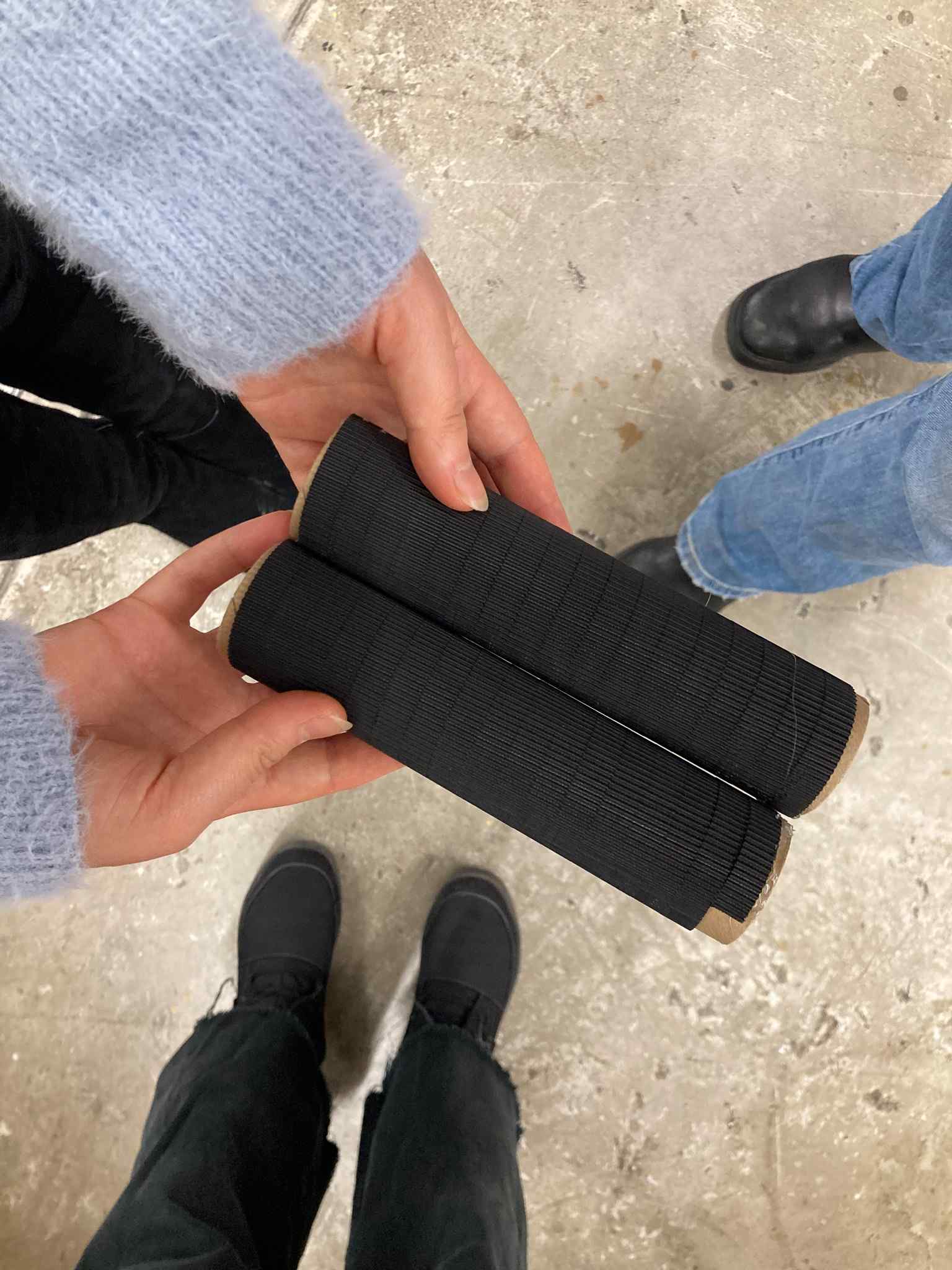
We decided to try a version of this motorized feeder, switching the follower back to the bottom so that the feeder wheel would be less likely to get tangled. To create prototype feeder and follower wheels, Rehana and Selin wrapped a rubberized belt material around two stiff cardboard tubes and glued the ends in place.
To test the motor’s capabilities, we hooked it up to a benchtop power. Wanting to be able to see the output, we wrapped a rubber band around the rotational shaft, and looped a zip tie around this. Then, when we cranked up the voltage, we could see the movement of the zip tie.
This worked, so we graduated to trying to attached our feeder roller to the motor shaft. Claire wrapped the shaft with a few rubber bands for grip, and then wedged a rubberized LEGO tire over these. This was almost wide enough to friction-fit into the center of our feeder wheel but not quite, so Claire added some blue tape and medical vinyl for grip. This did the trick, and we were able to squeeze the homemade system onto the motor shaft and into the hollow roller. Now we could spin the feeder wheel with the motor!
We tested out our system, which worked well... until we cranked the voltage high enough that the centrifugal force ripped the belt off of its glue and flung it around at us. This is why we wear safety glasses!
We replaced the belt with strong double-sided tape and tried again. This time, we got a little functionality but not much. We also had trouble maintaining even contact between the feeder roll and follower. Because the follower was cantilevered off its connection point to the motor, one end wanted to droop slightly lower than the other. This resulted in more downward force at one particular spot, which was enough to friction-burn a hole through the toilet paper there.
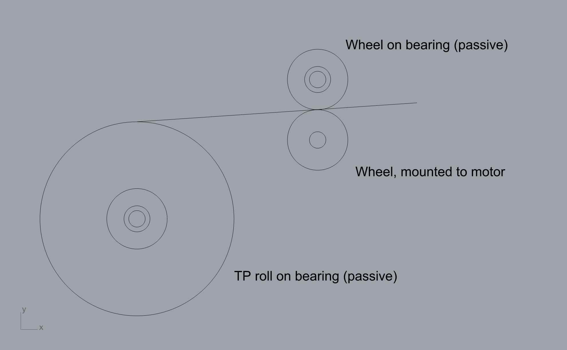
Eventually, through pure trial and error, we landed on a configuration that worked! Instead of the feeder wheel being stacked directly on top of the follower, we discovered that it needed to be stacked diagonally to it, set slightly back, in order to achieve the throw we were hoping for.
It was an exciting end to the evening, as we finally had proof of concept! We decided to add a fan back into the equation as well, hoping to supply some additional lift.
Notes
We noted some things that would need to be figured out in order to solidify the design:- support frame for TP roll, feeder wheel, and follower wheel.
- how to attach fan into support structure
- how to attach motor shaft to feeder wheel
- find/make a powerful enough fan to generate lift
- make better feeder and follower wheels
- mount all three wheels (TP, feeder, follower) in way that guarantees they are balanced on perfectly centered axels (no slop, as we had when we just slid PVC pipes through their centers and let them hang.)
Saturday
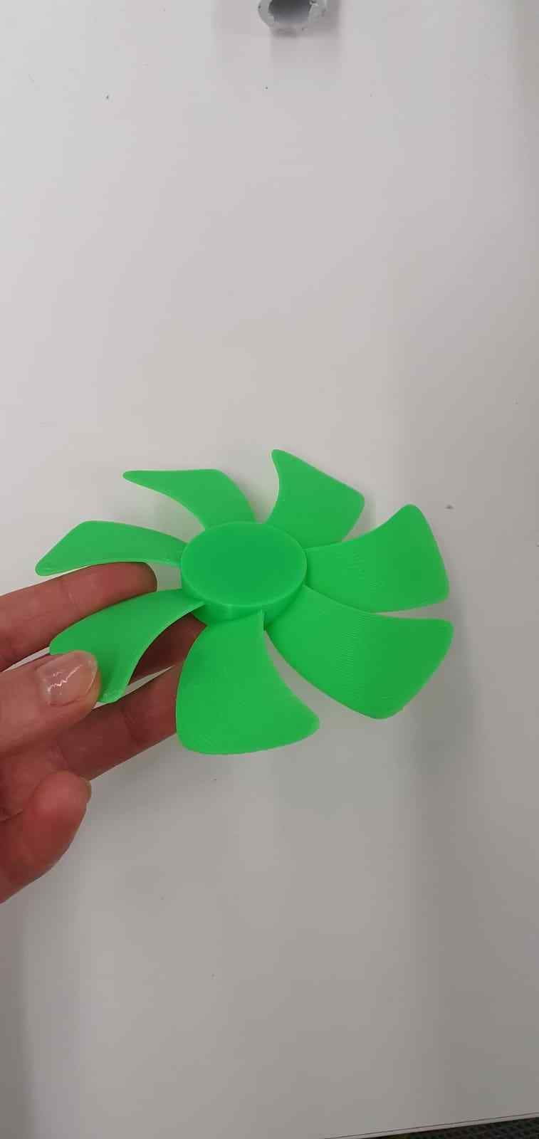
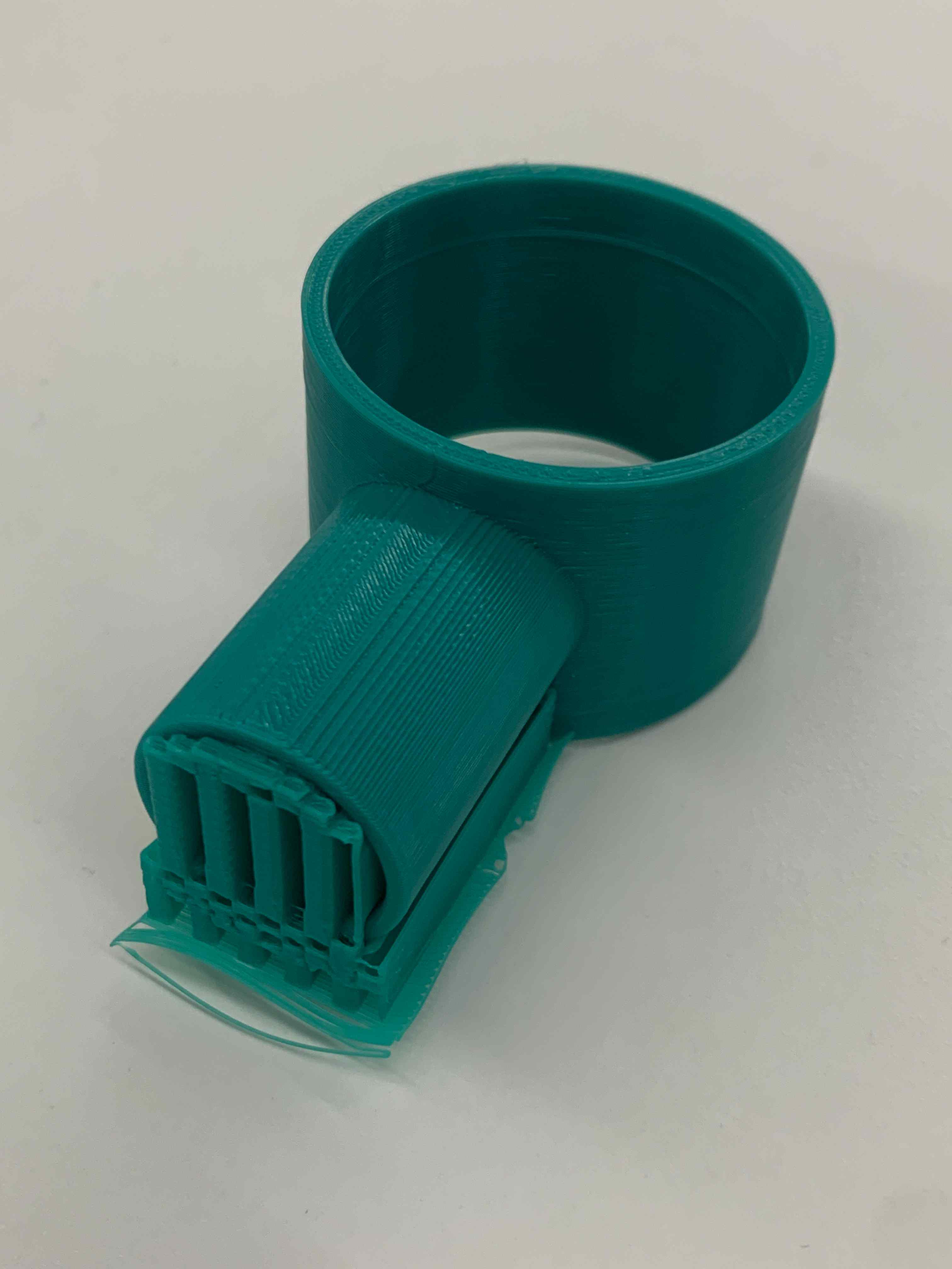
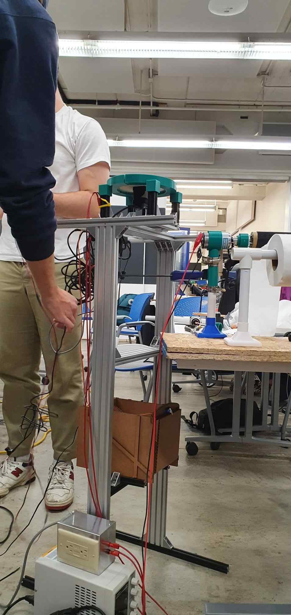
The next day, we set out to refine our feeder mechanism and figure out a framework and fan. Since we were hoping to make our own fan by connecting 3D printed blades and housing to a motor, Rehana got started on those designs and successfully printed a set of fan blades.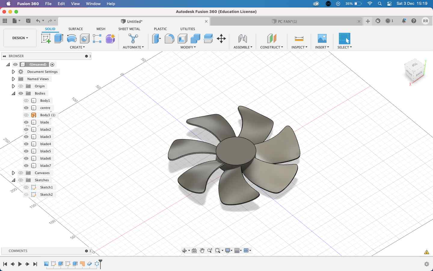
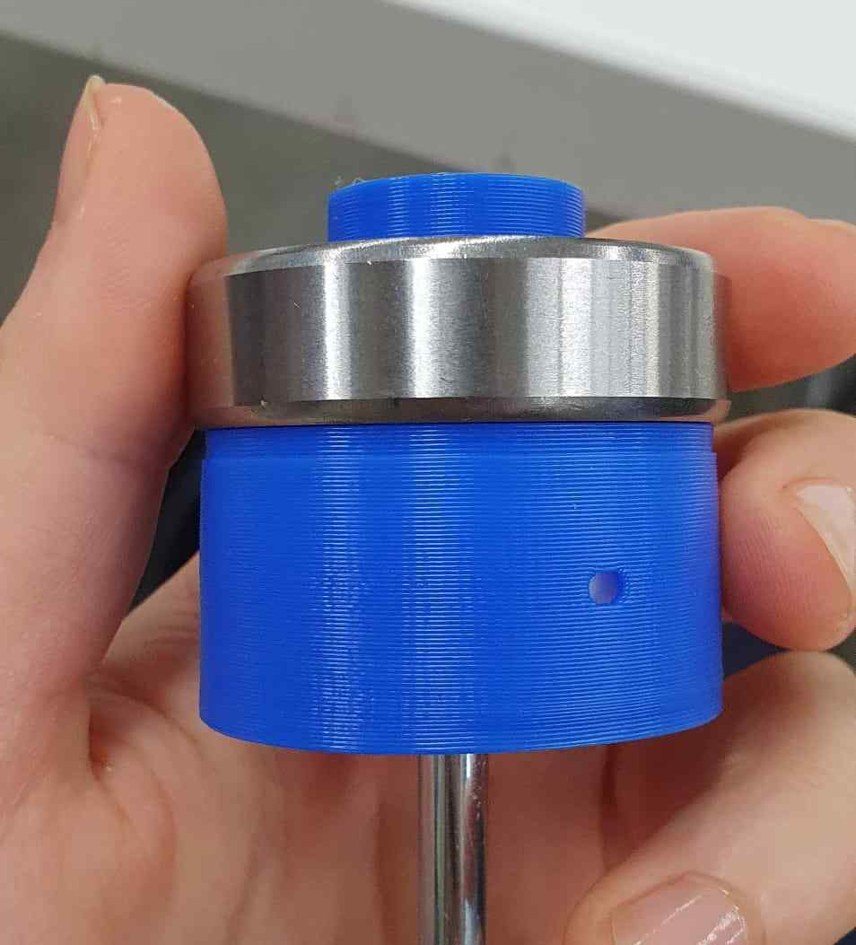
Arthur made a trek to the hardware store to buy some paint rollers, which solved our need for a tension-fit system to keep all of our various spools (x3: TP, feeder, follower) all centered on their axles. Excellent—that was one problem solved.
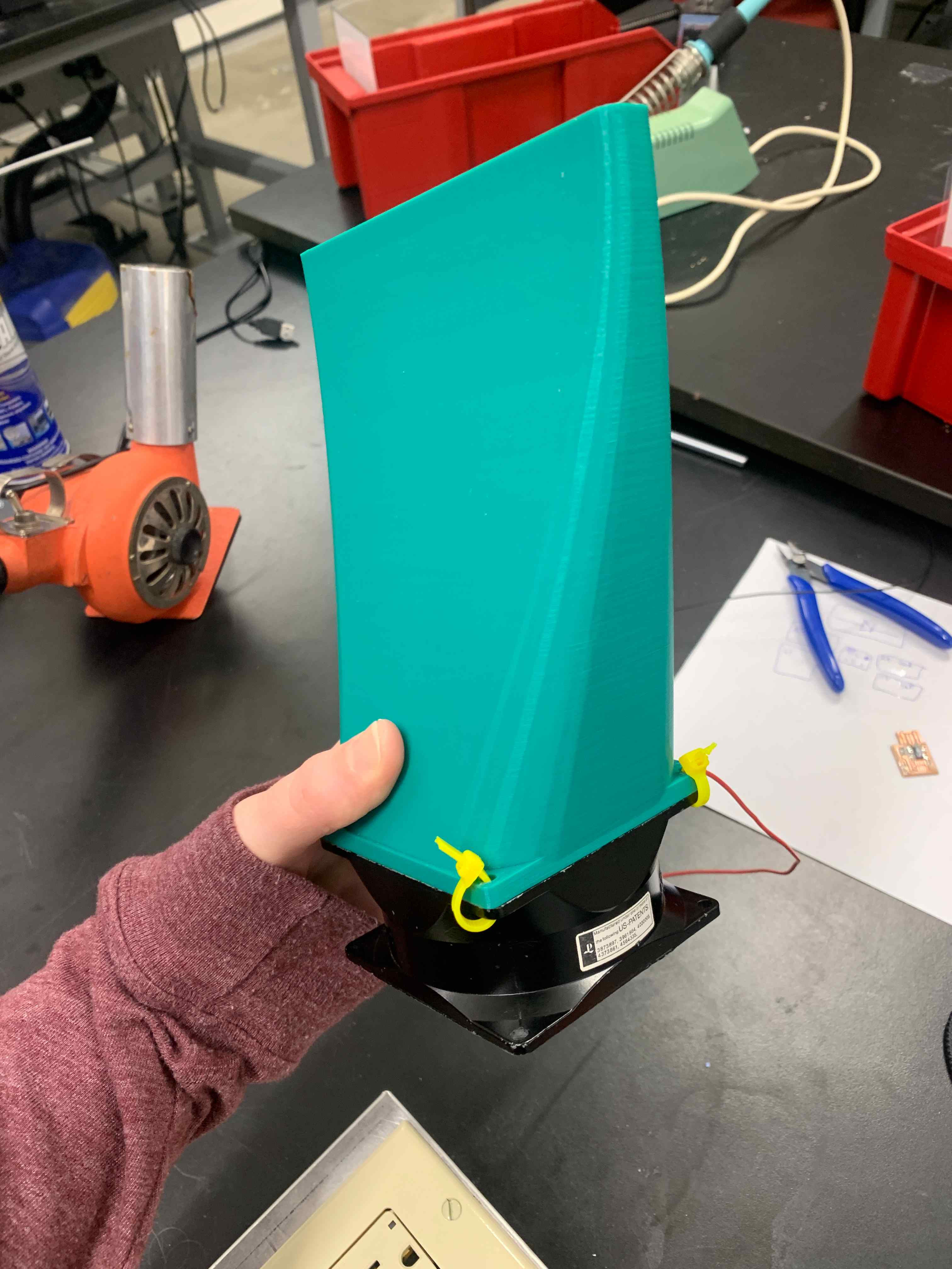
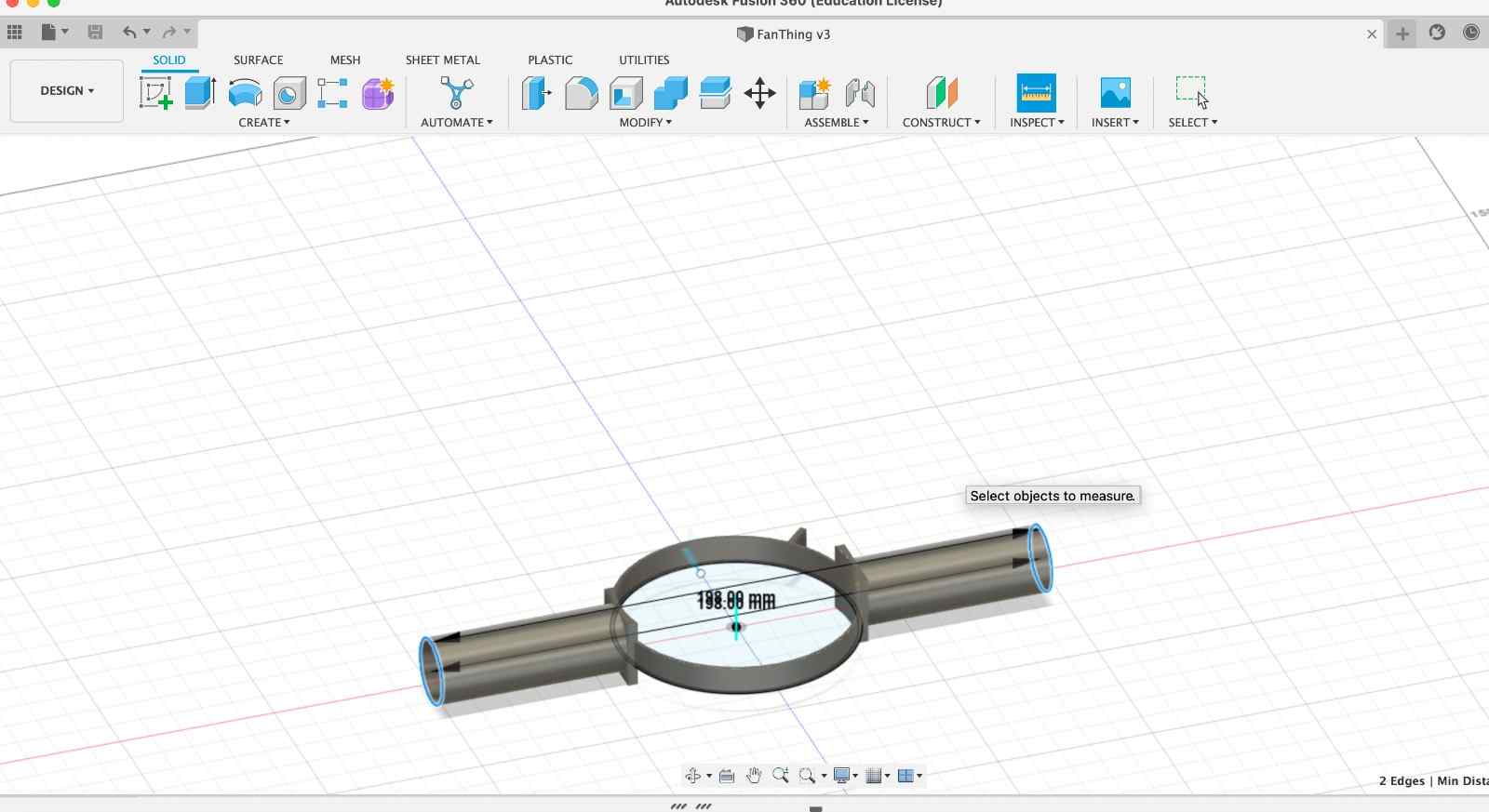
We also needed a way to focus our little fan’s airflow, so Taili designed a nozzle in Fusion360 that would screw to the fan’s frame. He used the “loft” feature to taper its shape into a long, flat slit.
Nathan gave us a few universal connectors that would slide over the motor’s shaft and get tightened in place via set screws. However, we still needed to figure out how to attach that connector to our paint roller.
The center hole in our connector was 4mm in diameter and the motor shaft was 5mm, so Sondos used the drill press to bore out the center of the connector to 5mm to match.
We initially figured we would just screw directly into the paint roller’s plastic caps, so Claire and Arthur did some measuring to find the center, putting tape around this to triangulate it, and then stacking the washer on top to mark the holes for the screws but then when drilling these, the center portion of the plastic cap popped off entirely! So we tried epoxying it in place, but the epoxy didn’t adhere well to the plastic, and we were worried about accidentally gluing the axle in place.
To solve this, Arthur designed and 3D printed a press-fit cap that would slide over the plastic end of the paint roller, parameterizing it to measurements taken from the motor and adding holes in the sides so we could screw it in place for added security. He also created a circular indent inside its “cap” to accommodate the connector’s washer.
When it was done printing, Claire removed the supports and clamped it into the bench vice. She wedged the washer into its press-fit slot and used it as a guide to drill screw holes through the rest of the cap.
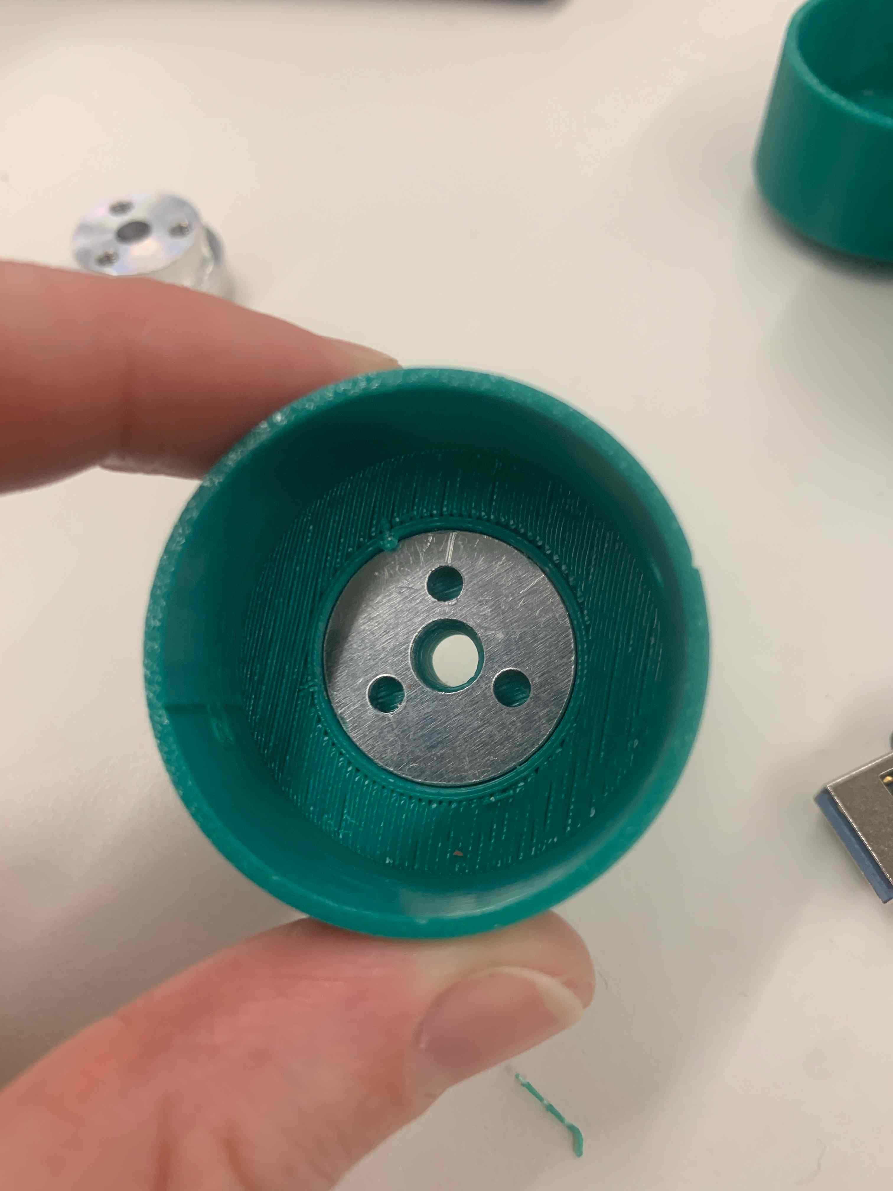
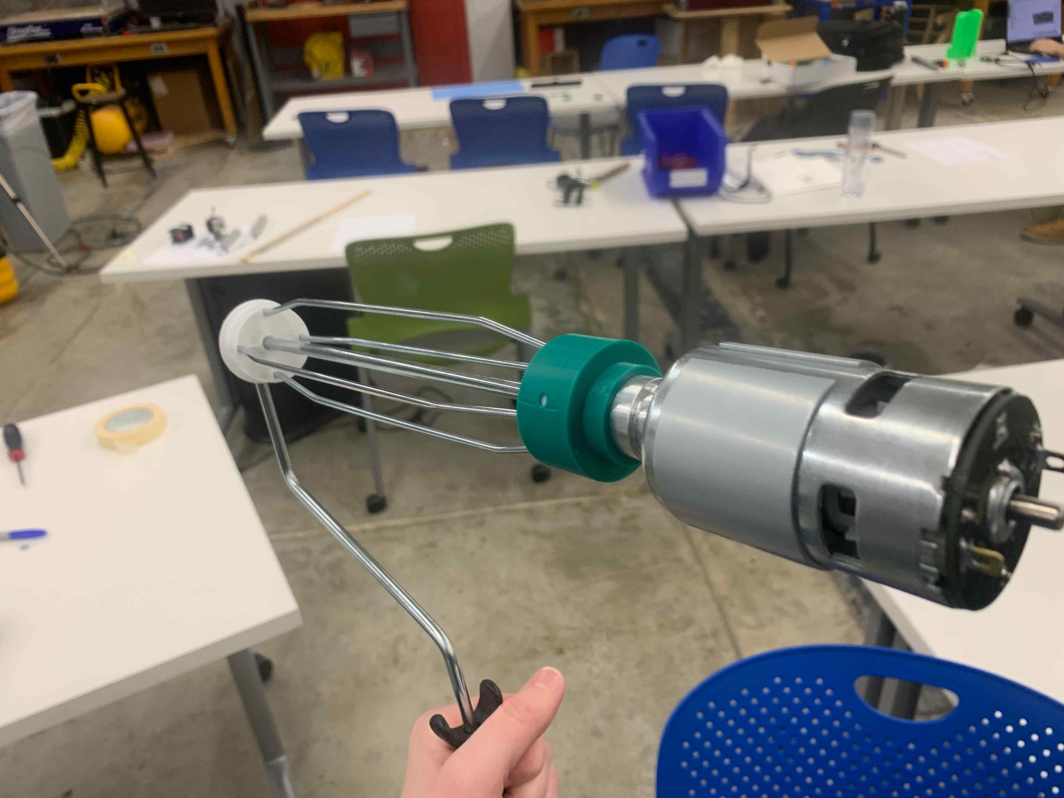
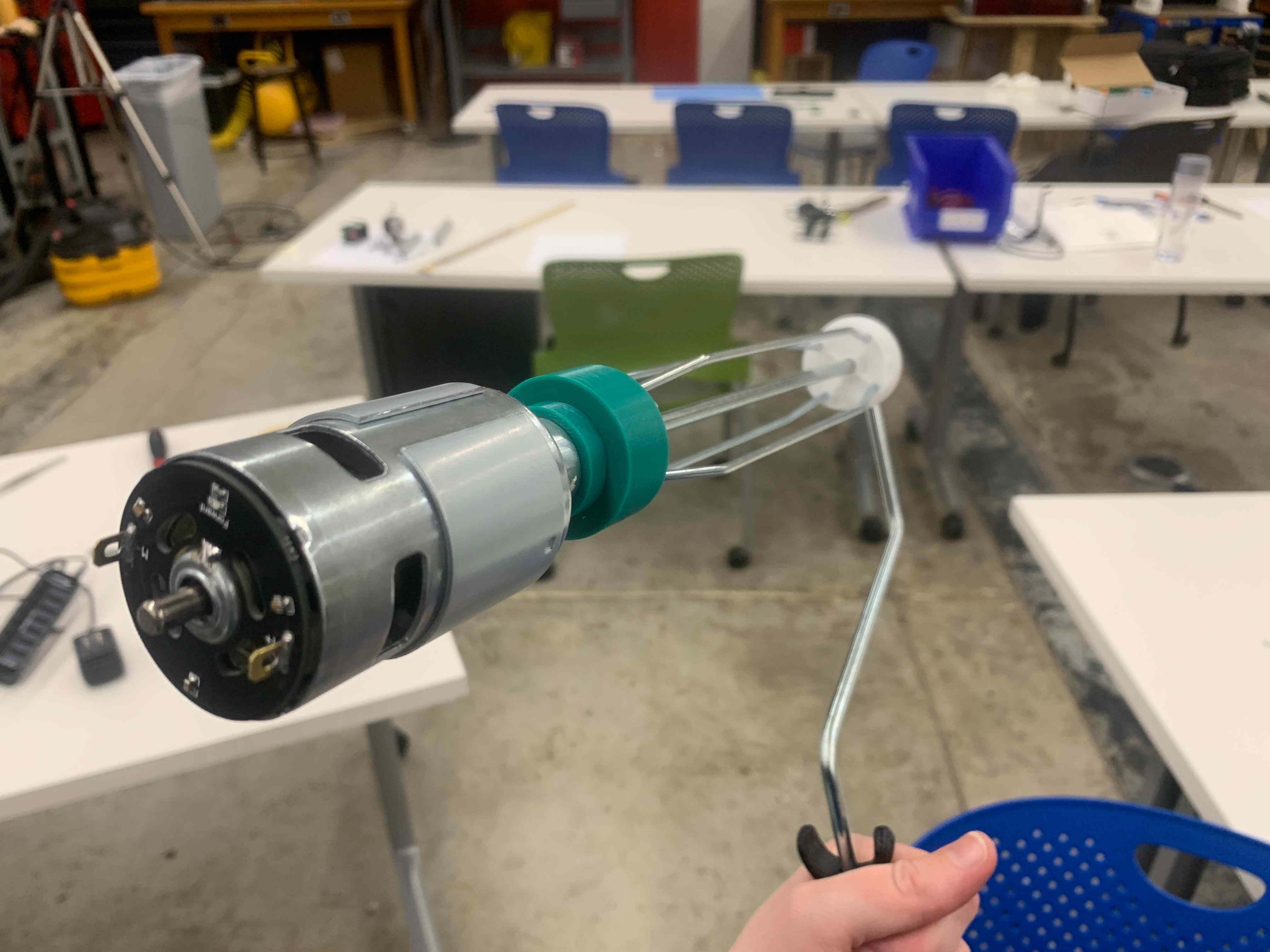
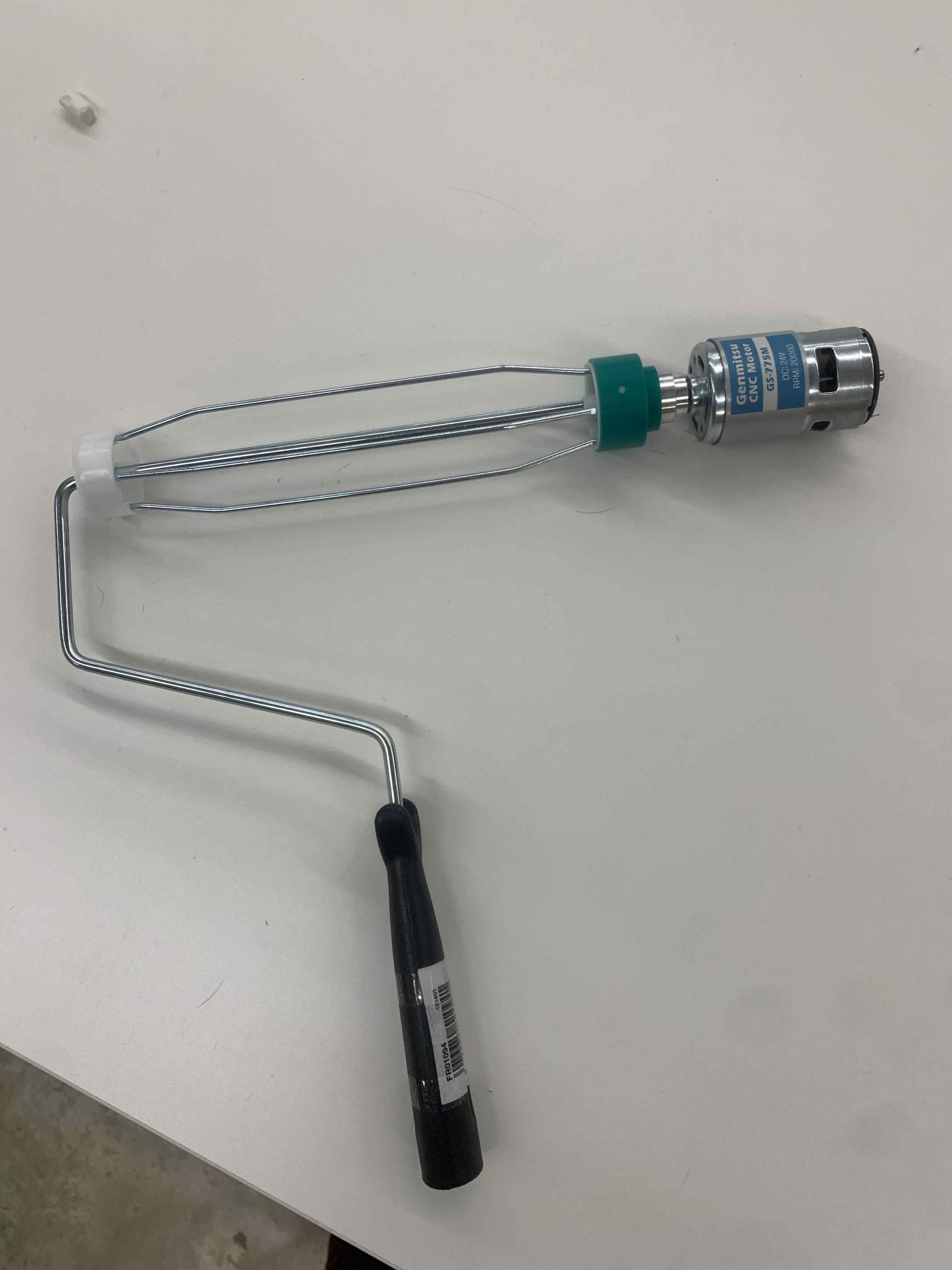
Finally, she screwed the metal connector to the 3D-printed cap, press-fit the cap around the plastic end of the paint roller, inserted the motor shaft into the center hole, and tightened the set screws to secure it in place. Now we had a motorized spinner! Once we added our rubber-covered roller, this piece would become our feeder wheel.
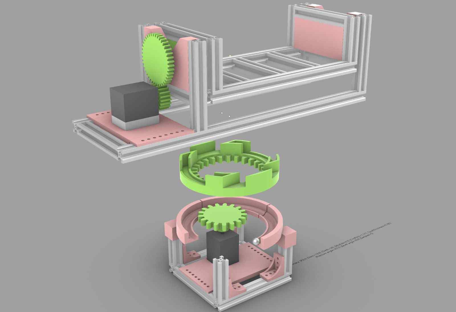
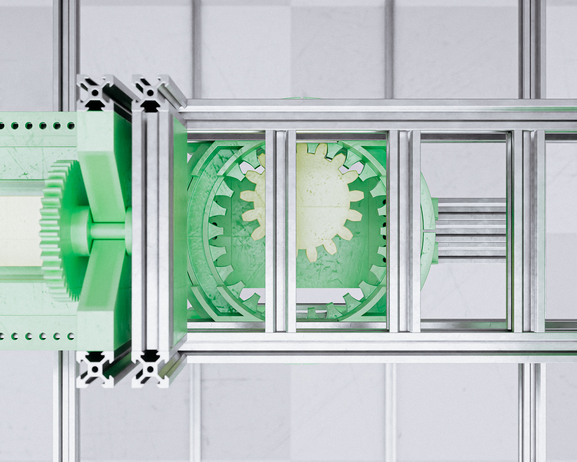
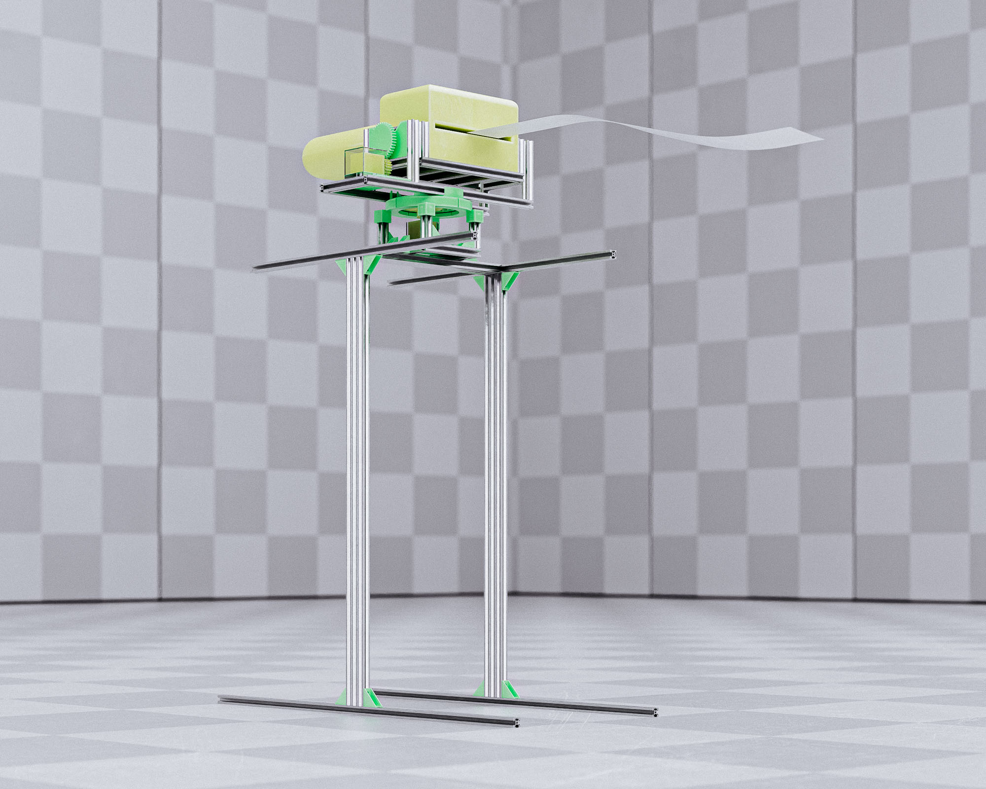
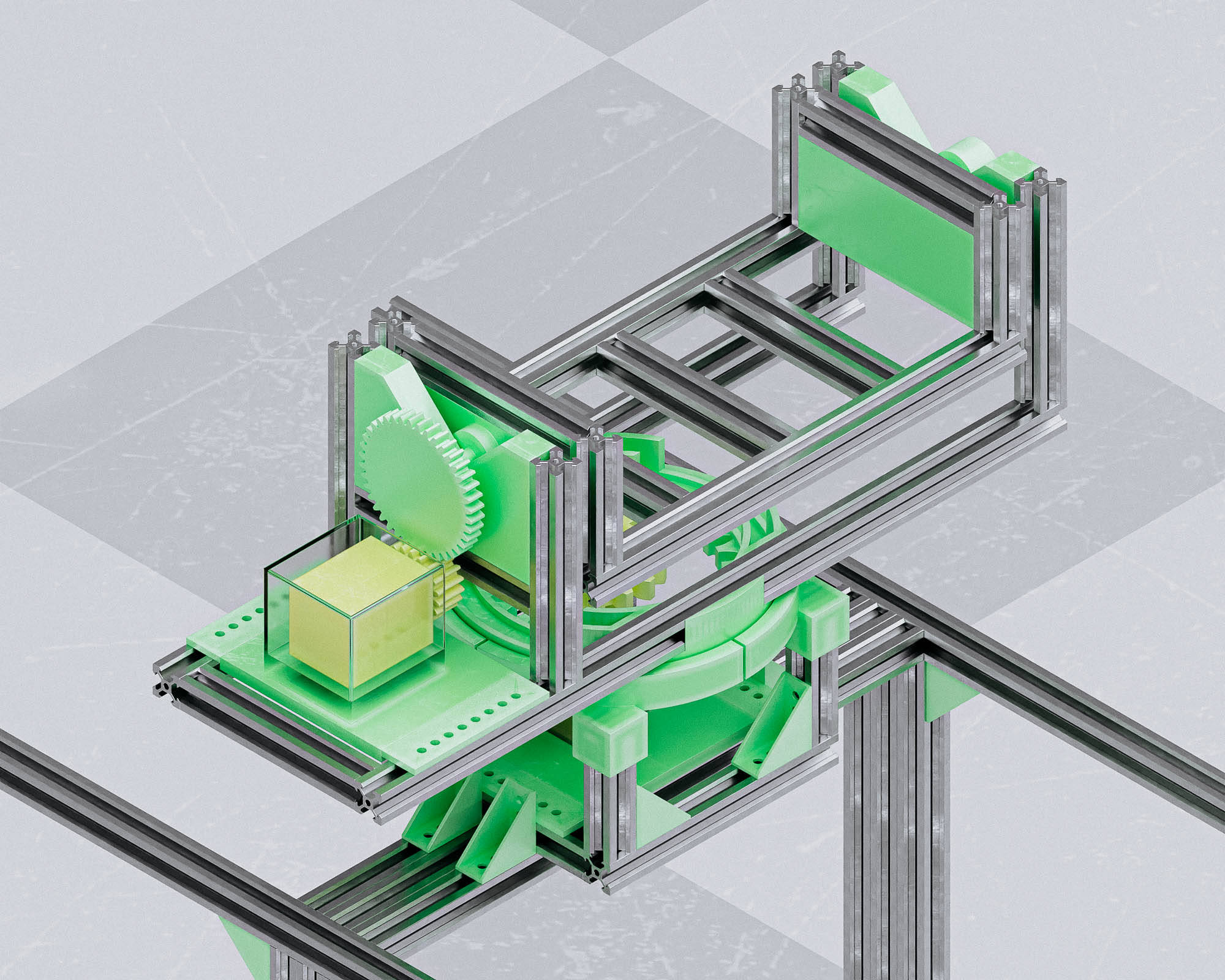
Nix came through with a beautifully designed and rendered system for the pan-and-tilt mechanism. This had two gear-driven systems: one that would control the side-to-side pan movement, and another that would pivot up and down to allow us to aim the system. His design was color-coded to show which pieces needed to be 3D printed.
Taili spent much of the day designing and assembling the machine’s supporting frame from metal extrusion. It looked great when he was done! We also needed components to mount the motor to our PVC frame, mount our fan in place, and mount our follower wheel and toilet paper spool. Arthur found some bearings that were similar in size to the paint roller ends, so we decided to create caps that would interface with these. Rehana designed and 3D printed connector mechanisms that would fit snuggly over the paint roller ends on one side and slot into the center of the bearings on the other.
Sondos designed a set of linked caps intended to hold the feeder and follower wheels together at the correct diagonal angle from one another. Meanwhile, Noy designed a collar that would fit around the fan. Bars sticking out on either side replicated PVC pipe so that they could mount easily into PVC connectors.
Claire designed a coupler that would sleeve around the motor and mount to a PVC stand.
Arthur designed feet for the PVC framework, complete with screw holes so we could bolt the whole system down to a surface plate when finished. After realizing the print time for each unit was 3+ hours, he then simplified their design a bit.
Monday
Redesigning
Sondos went to the store to look at alternative fans, and Taili’s design had finished 3D printing overnight and looked promising. For the sake of expediency, used zipties to quickly attach it to our fan. Although it didn’t produce a ton of air (nowhere near a leafblower’s force), we were satisfied with this as a first spiral, and chose to focus on the remaining components before revising this further. (Spoiler alert: we did end up using the storebought fan in the end). She also used glue to attach the full length of the rubber belt around the PVC pipe, little by little. This would be our feeder.
After a conversation with Quentin and Arthur, we pivoted to using rubber LEGO wheels that would spin freely on a wire for our follower mechanism instead of the more complex bearing system. Arthur designed and printed connectors for this and the paint roller feeder wheel.
Monday evening, we realized that no one had yet started the 3D prints for Nix’s prepared CAD files. Nix stopped by the lab briefly after his classes and walked through his system. His design comprised two parts: aluminum extrusions and 3D printed connectors and gear drives.
Unfortunately, the files came through corrupt and unable to open. The next attempt came through in the wrong dimensions. It took several tries to generate the correct G-Code files for printing, at which point we loaded as many we could onto the available printers to print overnight.
TUESDAY
Crunch Time = Triage
Unfortunately, only three of Nix’s six pieces printed successfully overnight Monday. Two were still printing the next morning (Tuesday), but we were down to two functional printers in the science center lab (shared with PS70, who also had a final project due imminently). Nathan pointed out that we shouldn’t be using 3D printers for most of these parts anyway, and 3D printing should only be a last resort. Noy led the charge looking for alternative options.These included:
- Using the GSD printers, if any were available
- Mill the parts at the science center (shopbot or laser cutter)
So we decided to mill the flat pieces instead. Taili graciously volunteered to translate the stl files into 2D shapes for the laser cutter, and we found some HDPE in the shop that we could use. Arthur designed a new, simpler mechanism to replace Nix’s. This would pan only instead of tilting. He made the trek to SEC at 2am to start the print. Treyden tried three different options for the power, but we had trouble with the power source. Nix took on the digital simulation and visualisation. As Nix is home sick on Tuesday due to taking vaccines on Monday, he decided to create a couple of digital simulations and visualization for communicating our machine design, even though there is a certain extent of compromise between the initial design and the final build. He mainly focuses on the mechanical movement parts, as we don’t have a CAD file of the paper feeder part, which is simplified and conceptually visualized. He rigged the pan/tilt module, and created an intuitive interface to control horizontal and vertical angles, and paper feeder frequency in Cinema 4D. Then he used the bullet physics system to simulate the paper movement with soft-body dynamics. Finally, there are a couple of exquisite realistic still images, and three animation videos to show how the machine (ideally supposed) to work.
WEDNESDAY
Zhuoyue swooped in with an incredible automatic tracking system, which ran off a camera and enabled our machine to recognize a person and turn toward them before and while launching.Meanwhile, Alexia and Jessica finished their final iteration for the marble deployment mechanism. Alexia’s contained marble ramp was equipped with a gravity-driven trapdoor. Jessica’s code would trigger a servo to open its latch when a human was detected.
And it worked! Beautifully. It sent marbles scattering everywhere to trip our poor boobytrap victim.
Before we get to the actual assembling, we took a quick tea break:

Assembly Process
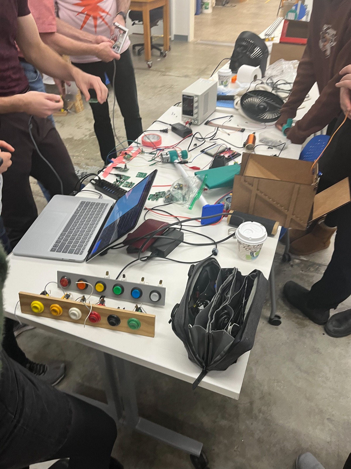
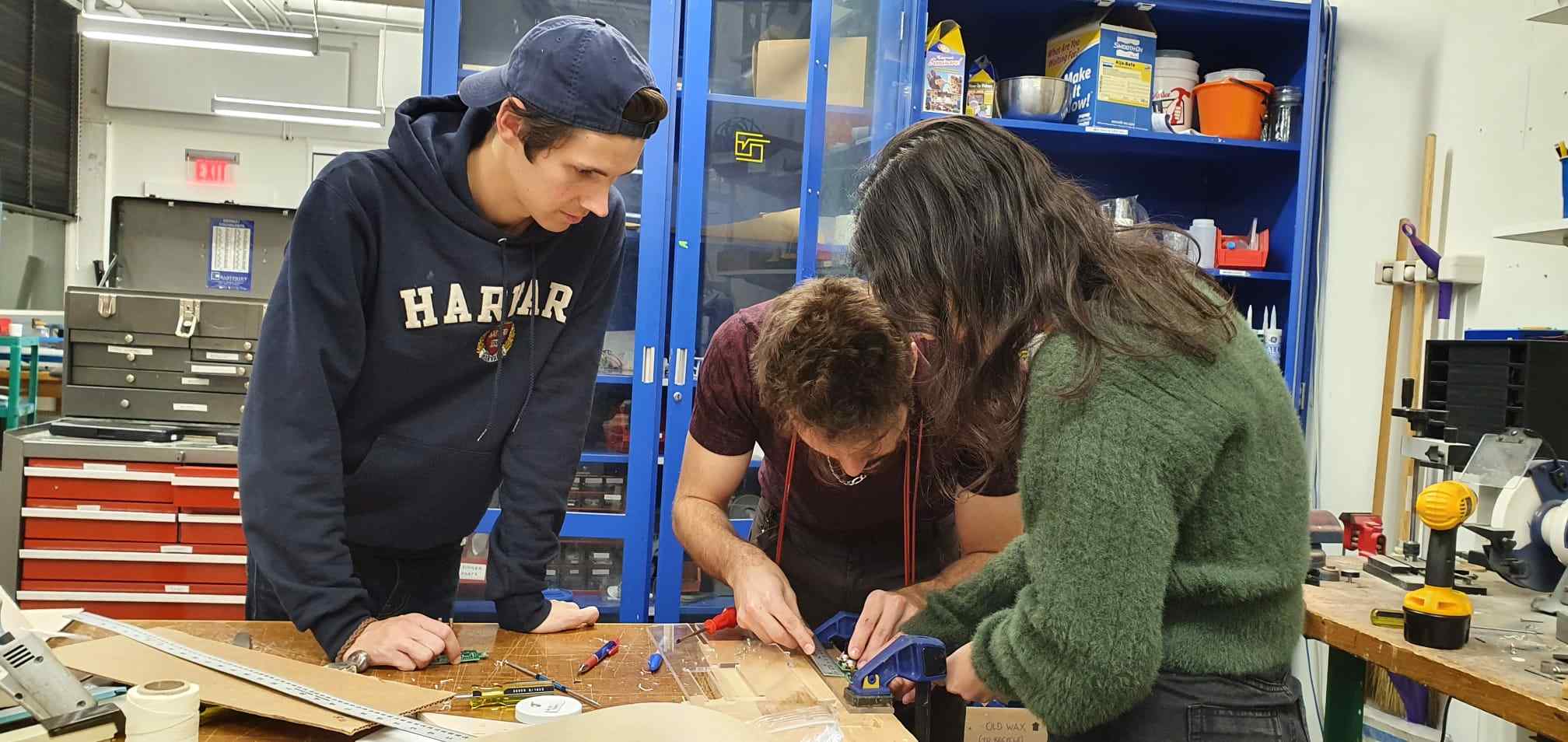
We started off by placing the marble team’s box and the fan into the metal frame Taili built. Arthur, Treyden, and Cedric finalized the mechanisms of the input devices and how many boards would be installed in the design.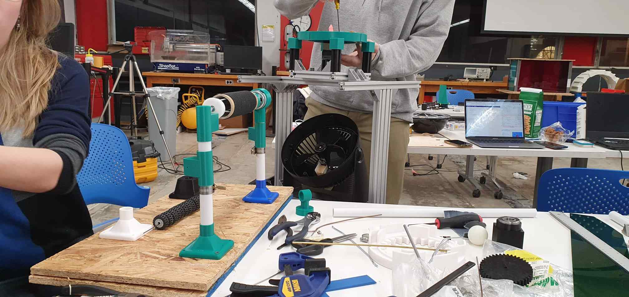
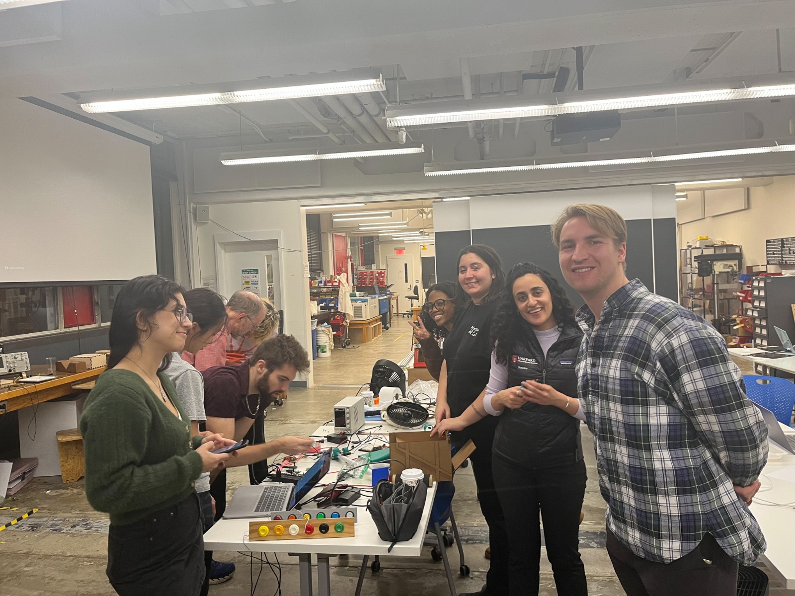
At the lab, it was mayhem indeed:
And look at those smiles :)
Meanwhile, Claire and Noy were figuring out the dispenser system. Noy cut PVC to length while Claire screwed the 3D printed feet to a few sheets of OSB. This wouldn’t be the final platform, but we needed the rigidity of a base in order to organize the rest of the structure correctly.
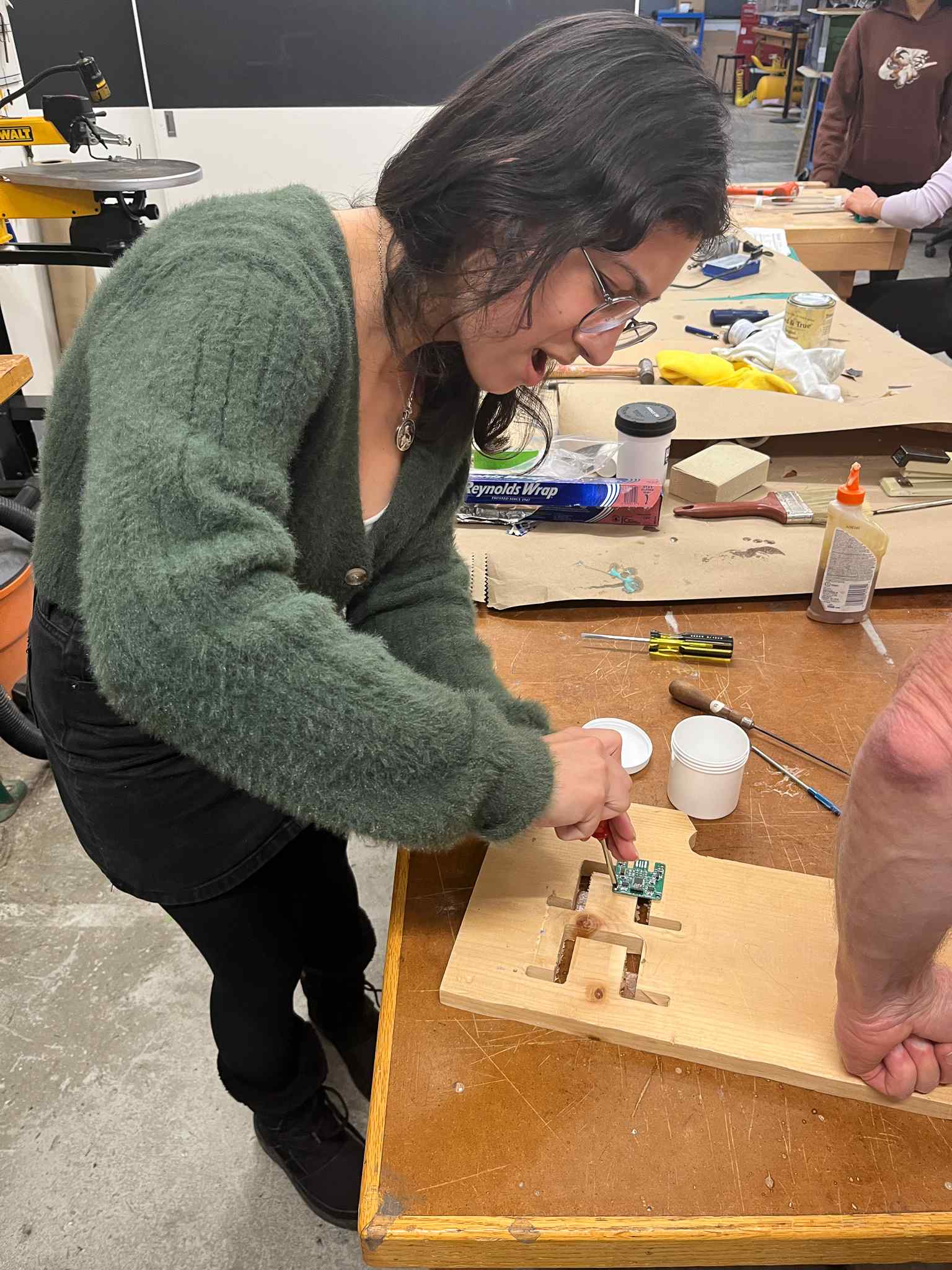
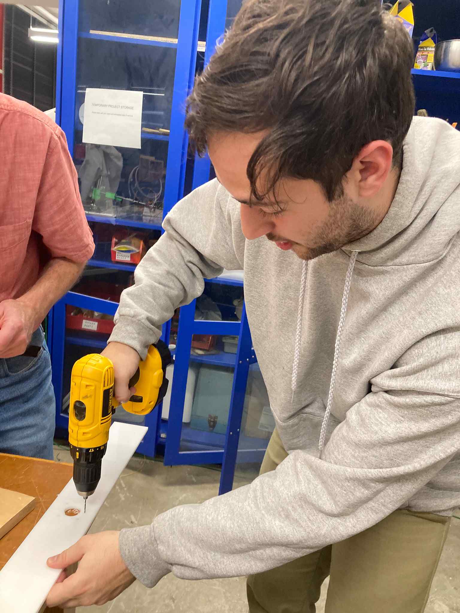
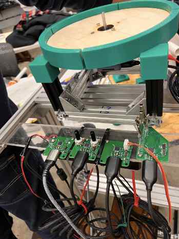
Once the PVC was in place along with Arthur’s 3D printed mounts, we discovered an issue: the follower didn’t quite make contact with the driver. We experimented for a while as a group before Noy cut two wooden pieces and drilled a hole in them for the rolling mechanism to stand. In order for the PCB’s to be able to be placed on the structure, Selin cut a piece of plexiglass and mounted the boards on it. Selin, Danny and Sondos tried to find the right drill for this process.
We had some difficulties in finding the right power source for our system. The boards needed more than 2A to start the movement. Treyden, Arthur, Cedric and Selin placed the boards and connected each one of them to separate USBs.
Then Treyden started the process of checking if the boards are functioning properly. We toiled through some debugging in order to get everything functional, but finally did! The last step was to transfer the dispenser subsystem to the more polished plate. We cut one corner off the square, base, but found that the plate sat lopsided due to unequal weight distribution. There was some back and forth about whether to shift the balance point underneath the system or to cut off the diagonally opposite corner as well to balance things out. We eventually settled on the latter, and things worked! HOORAY! Lots of cheering ensued.
INPUT TEAM
Once we had decided on building a TP shooter with a marble trap, the input team (Treyden, Cedrick, Caine, Selin, Kia, Zhuoyue, & Arthur), started considering the inputs of the device and which sensors would be the best fit for the tasks. With the goal of creating a Home Alone inspired machine, some thoughts that immediately came to mind were how we would detect an intruder, how we will target the intruder, how the traps will be triggered, and more. The features and execution plans we initially considered were: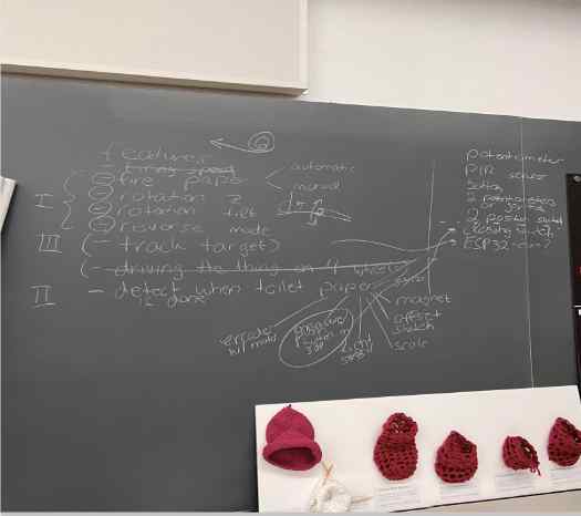
Firing Speed:
- The firing speed was initially intended for us to be able to vary the speed of the motor that would be firing the tissue paper. This would affect how far the toilet paper is to be shot. We initially considered a potentiometer or a joystick to control this function.
- We decided not to control firing speed as it did not seem to have a great useful effect on tissue firing.
Firing toiler paper:
- For input to control toilet paper dispensing, we wanted to have a toggle that would control if the dispensing would be automated or manual. Manual would allow for firing to occur along with the manual controlling of the positioning to target and fire. Automation would allow us to run at a default speed where the toilet paper could be dispensed for a certain amount of time or user tracking.
- A button will be used for this toggle.
Rotation on the Z axis:
- We wanted the shooter to be able to work like a tank. For rotation around the z-axis, it would enable us to direct the shooter to the left or right for targeted firing.
- We decided that a potentiometer or joystick should be used for the input values that will control the output of the motors.
Rotation tilt:
- Tilting would give us the ability to move the firing head up and down for a wider firing range. We decided that a potentiometer or joystick should be used for the input values that will control the output of the motors.
- We decided not to have motion in this direction for the scope of the machine and to fit into the timespan we have.
Reverse mode:
- A key consideration was that we didn’t want to waste a ton of toilet paper, so we wanted to be able to reverse the toilet paper roll after firing. We realized that this could be controlled by the same toggle that will trigger the dispensing of toilet paper.
Track Target:
- A consideration was to use facial recognition and body/person tracking to control the direction of the firing mechanisms and dispensing. This would give us the ability to follow a person and fire at them while they are detected. The direction of the tilt and rotation plus the firing mechanism would be triggered by the detection, which has the added benefit of tracking versus only detecting.
Driving:
- In initial considerations, we considered having the shooter be mobile on four wheels. The idea behind that decision was that the machine could follow an intruder to continue firing toilet paper. We planned to use joysticks to control the drive motors as an easy way to drive around.
- We decided this was out of scope for the timeframe but would be something to do in the future.
When empty/time to reverse:
- In order to not waste a ton of toilet paper, we wanted to be able to rewind up the toilet paper roll. This means that we would need to detect when the paper runs out. We ideated on a couple of input options for this challenge.
- Gyroscope
- Using the measure of orientation and angular velocity to determine the amount of rotations it would take for the toiler paper roll to be finished, then that variable can be used to know when the limit has been reached and to trigger reverse.
- Magnet
- Using a magnet was a solution designed to allow us to create an encoder on our motor. From there we could design a counter based on the electrical signal and utilize that to control when the motor is reversed.
- Motor with encoder
- A motor with an encoder already on it would allow us to count the amount of rotations it would take to empty the roll. The benefit is that the motor has an encoder.
- The dispensing mechanism team let us know that the motors we had available with encoders did not have the power needed to dispense the toilet paper at the desired ideal rate.
- Light sensor
- light sensor could be used to detect the change in color between the white or the toilet paper and the brown of the roll.
- Scale
- Detecting the weight of the toilet paper roll changing using a pressure sensor or scale was considered.
- We opted against the option due to variations in toilet paper rolls and a lack of options for placement in the mechanical design.
- Offset switch
- This idea was to have a clamp under the toilet paper roll tube and on top of the toilet paper. Once the clamp was within a certain range or pressing together on both ends, it would trigger the reversal.
- This idea was not compatible with the desired mechanical design, and we were hesitant about how the reversing of the role would be able to go smoothly. It seemed more complicated than it needed to be.
- We needed to detect when a person was within a certain range to trigger the machine's start. The PIR and ultrasonic sensors were considered for this. The PIR detection uses heat to detect when a person is within a wide range. The ultrasonic sensor worked similarly since it sent out a signal to echo back, which is used to calculate the distance of an object.
Testing
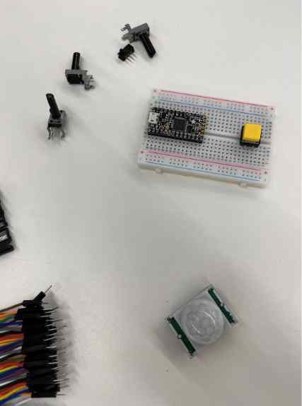
We began by testing the sensors. We started with an Adafruit ItsyBitsy, and collected the desired input devices, a breadboard, and wiring needed to get the data feedback from each device.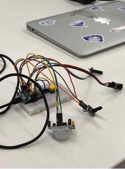
Unfortunately, this was unsuccessful, and the board did not appear through usb or on Arduino.
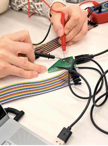
Next, we went to the parts that we were given for the week and soldered the pin out board.
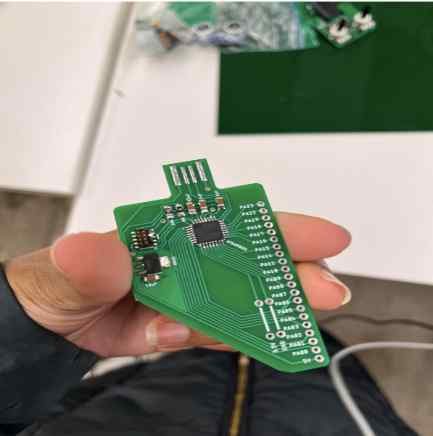
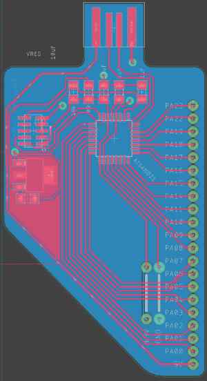
We spent some time troubleshooting, we had some floating pins and poor connections. Once this was fixed, we were able to bootload and program this board.
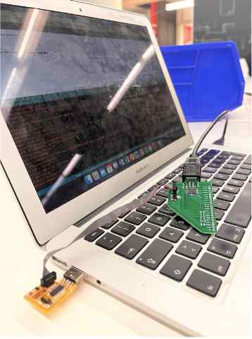
After the board was made to be able to be programmed, we collected the sensors and a breadboard to begin coding in Arduino to observe their data outputs.
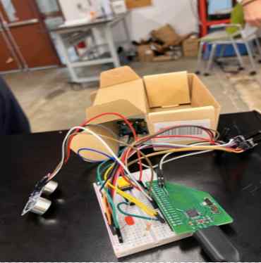
PIR
- The PIR sensor was very sensitive and did not seem to accurately read the detection of a person. We created a shielded tunnel for it which increased the detection accuracy. We adjusted the potentiometers on the PIR to adjust the sensitivity and timing delay. With changing and manipulating these features, we were able to get a fairly responsive reading. We connected an LED that was triggered when an object was detected to give more visual output since we were reading values from all of the sensors.
Ultrasonic
- The ultrasonic sensor had the benefits of being able to adjust the ping rate and distance from the object that we wanted to detect. This gave us a more focused range, but the timing delay did not allow for the program to be responsive as quickly as we would like. We concluded that the ultrasonic may be best for close range detection
Button, Switch
- This worked effectively, returning values of 0 and 1 depending on the state.
Potentiometer
- The potentiometers worked and displayed the desired range of values based on turning.
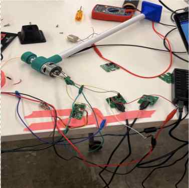
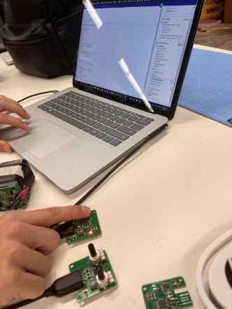
Boards
Next, we utilized the provided boards to support the different desired inputs. We created the firmware for the pin out board we soldered to use with the PIR sensor. The other boards provided that we used are the potentiometer board, button board and motor board. Modular things allowed us to flash the boards and then program them to talk to eachother. Once the usbs are connected to the same device they are able to send data to and from one another as needed.
Here’s the set up for and part of the code the code we used in modular things.
//—-------------------
//This is the code for the breadboard // button // potentiometers // and motors
const div = document.createElement("div");
div.style = `
padding: 10px;
background: lightblue;
color: black;
height: 100%;
`
div.innerHTML = `
`
const lightSwitch = div.querySelector(".light-switch");
turnt.setCurrentScale(0.75)
turnt.setStepsPerUnit(30)
turnt.setVelocity(200)
turnt.setAccel(750)
let counter = 1;
let value = 0;
lightSwitch.addEventListener("click", () => {
value = value === 0 ? 1 : 0;
mossyBoi.setGate(value);
lightSwitch.innerText = value === 0 ? "off" : "on";
})
snowflake.onButtonStateChange((state) => {
if (state) return;
iawgz.setpin(counter % 2);
counter++;
})
loop(async () => {
const data = await Promise.all([
harvardpot.readPotentiometer(0),
harvardpot.readPotentiometer(1)
]);
console.log(data[0]);
turnt.absolute(-data[0]*10);
}, 30)
render(div)
//—--------------------
These are the three boards we used:
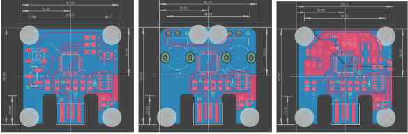
And these were all mounted on clear sheet of PVC which was then mounted on the side of the machine.
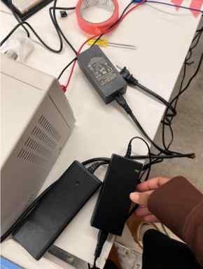
There was some trouble with powering the board. We tried various power supplies before settling on using the voltage regulator to provide the needed 4amps.
Facial Recognition & Tracking
Using modular things, allows us to talk to the motor using facial recognition software. Opencv.js (an open source computer vision and machine learning software library) was implemented into the module to do facial tracking, then the information was written to the motor. The motor's direction depends on the face location within the screen. The screen is divided by the center (i.e face on the left then the motor turns left. Face on the right then the motor turns right.) The face detection information is used to update the direction variable every second. Initially, we wanted to have two motors to do up/down &left/right, but with the decision to have one motor, we only look based on the vertical center line.- © Rehana Al-Soltane
- Design: HTML5 UP