I have some new thoughts for my final project. A source of daily annoyance for me is that I only have 1 light switch in my room, and it is very far from my bed. I'm incredibly prone for going to bed with the lights on instead of turning off the lights at night because of this. It most definitely takes away from the quality of sleep that I get, so I would like to change this part of my routine. I want to make a device that I could attach to my wall that I could trigger via bluetooth to flip the switch for me. I have the idea for how this would mechanically work in my head, and I'm planning on making a CAD animation to communicate my ideas over the next week.The only con of choosing this as the theme of my final project is that it isn't obvious to me the ways I could implement cool graphic elements into the final project, and that is what I generally am excited to make, so I am trying to think about how I could simultaneously make this a very cool and interesting design object for my room. Some of the constraints that I am imagining for the box are: weight - I need to be able to affix it to the wall using only command strips, so it shouldn't be too heavy. I also need to be able to use the light switch manually without engaging the mechanism (so it cannot perpetually rest/cover the light switch unless there's a way to engage the mechanism manually).
Design Choices
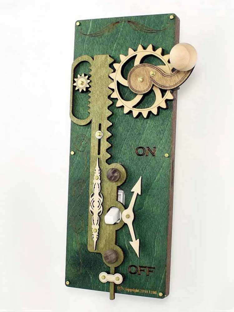
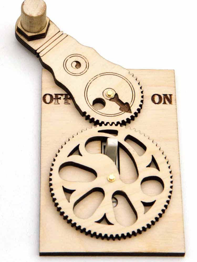
I am thinking more about what kinds of design choices I could make. I'm feeling a bit inspired by my earbuds, Nothing Ear 1s, that are known for their inconventional design by having a transparent casing that enables the viewer to see the mechanisms at work inside. It would also inspire me to make a cooler looking PCB (which I don't need inspiration for, but I would like it to be appreciated in the final work).Upon doing some research, I have found that there is a bit of precedent for these kinds of systems, in the form of something called a light switch complicator. Although they are not automated, I think that I could somewhat easily add a motor to it (with some trial and error to make sure that it can supply enough torque to actually move the light switch). There seem to be 2 existing kind of methodologies to moving the lightswitch; a rack and pinion, or a gear that rotates with a slot for the lightswitch.
Rack and Pinion Example
Gear and Slot Example
Despite being a mechanical engineer, I get a lot of anxiety making systems that have to work with electronics (which makes me work super slow and procrastinate and generally not enjoy life). Although in an ideal world I would like to do something a bit more original, I think that the best way to make sure that I actually make something rather than not finish the project is to do something with a good amount of existing work that I could refer to.
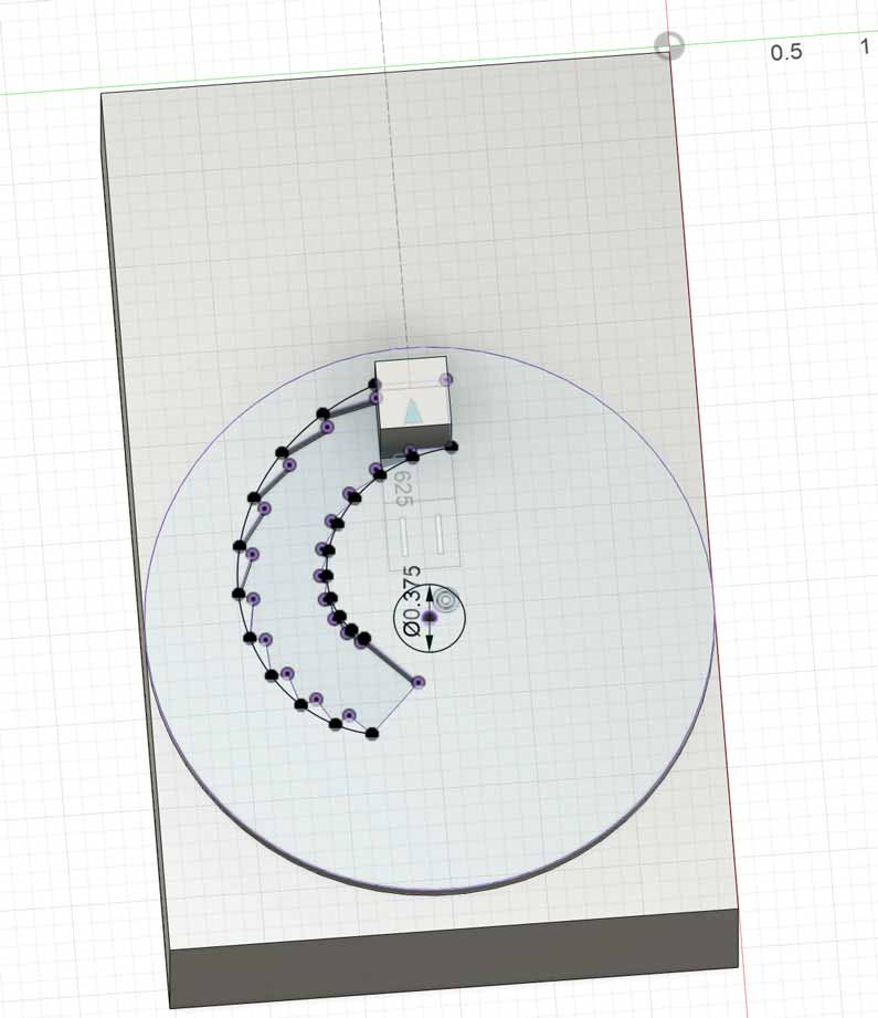
I thought the gear with slot idea looked super fascinating, so after measuring the dimensions of the light switch, I made a rough 3D model for the light switch box and painstakingly, rotated the gear and made projections to make a track for the rotation of the gear.
Gear and Slot CAD
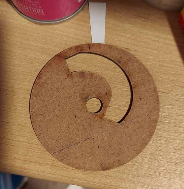
I then laser cut the disk to check whether the rotation of the disk would correspond to the movement of the lightswitch. And as seen below, it somewhat kind of worked. However, just by rotating it with my hand I noticed that it took a lot of force to rotate it to flip the lights back on. The switch really would push the gear out of place rather than nicely moving up and down.
Gear lasercut out of MDF
As such, although I think the gear with the slots look very nice, I think I'm going to re-design with the rack and pinion, as I have a bit more confidence it will use the mechanical power from the motor more efficiently, and work more consistently. The goal is to make something that functions regularly and functions well, and the aesthetics should design around those constraints.
CAD, Manufacturing and Assembly
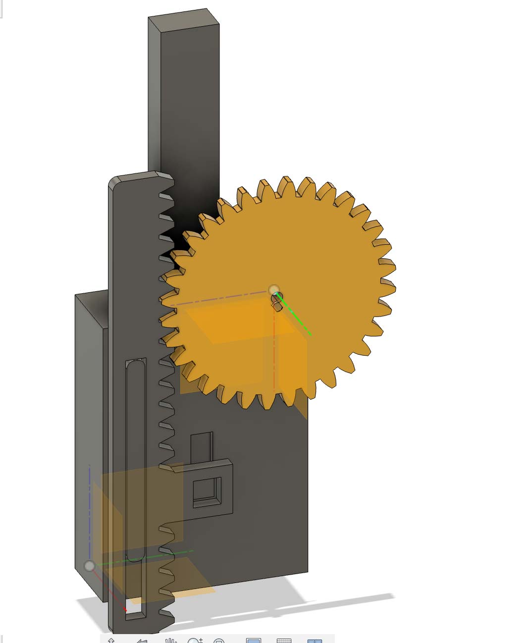
I've designed for the rack and pinion model using a 5V 28byj-48 stepper motor. I chose to use this motor because it is light, cheap, it can be run pretty reliably whilst using the microcontoller as the power source, and I also happened to have some on-hand already for a different class, so I already had access to them and understood how I would make them run.
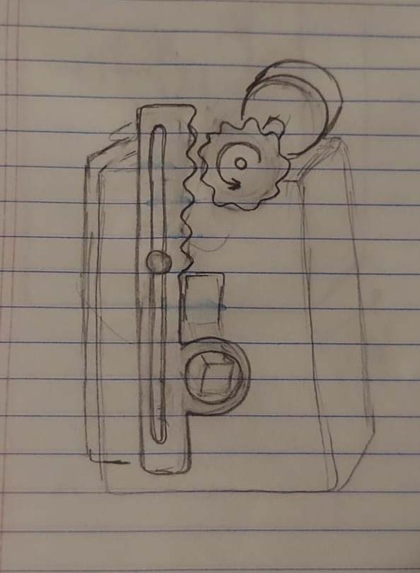
Sketch of the machine using a rack and pinion to flip a light switch
With this design, I created a shell that would sit on top of the light switch. My lightswitch is on a little extruded box, so it provided ample space for me to put the different components. I could easily place the motor on one side,the battery on the other, and the PCB fixed to the side. The shell could not be too thick as it would make it difficult for the rack to be able to pull on the switch, but did need to be thick and stable enough that it would not break as the motor exerted torque on it to be let free.
CAD with the 28byj-48 stepper motor
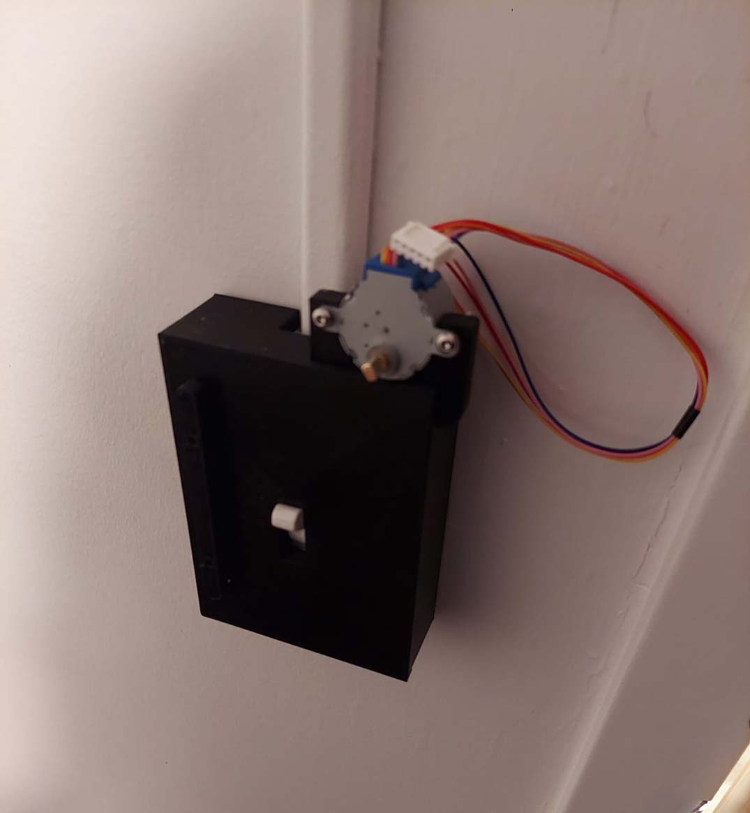
As soon as I had the part designed, I set out to complete the 3D-printing to ensure that the shell would fit right on the box. To my surprise, I had measured super accurately and it fit snug without having to force it. The placement of the rack and pinion worked, albeit a bit misaligned, and I could use the stepper to drive it, as seen below.
28byj-48 worked when no load was applied to it.
As seen here, the 3D print fit super well on the wall. But unfortunately, the motor was not strong enough to flip the switch.
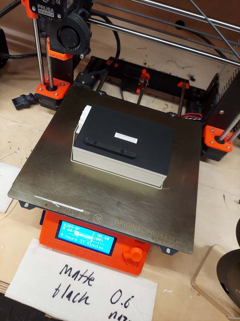
However, once I tested the box on my light switch, I realized that the motor was way too weak to flip the switch. As such, I looked around to find another motor, and came across some servos from a previous project. According to a google search, it takes about 1N of force to flip the switch, so I did some quick calculations to confirm that according to its spec sheet, while being driven at about 6V, the motor would provide more than enough force to move the switch. Having completed the redesign with some other minor changes, I 3D printed and lasercut again and started assembling.
3D printing new model for the stronger motor. I ran out of white filament as it was printing which led to it having a cool black and white coloring.
Upon assembling, I found some issues - first, I had designed the pinion to have the profile of the axle of the servo cut into it, but unfortunately, presumably due to kerf and the general meltiness of lasercutting 1/4" thick acrylic, the axle did not drive the pinion incredibly well, as seen below.
It's a bit difficult to see but it is not driving the gear efficiently or effectively.
However, I did have the attachments for the servo itself, which would be difficult for the acrylic to skip over, so I just redesigned the pinion to fit around the attachment, and laser cut additional disks to keep the placement of the pinion on the servo and on connected to the attachment. Once this was sorted, I also had issues with the motor coming out of the fasteners/being too strong to remain in its fasteners. When this issue occurred, I thought I was completely screwed, as I did not know how to fix it. However! this led me to one of my most important lessons; use tools! At first I lasercut the fixture out of acrylic and that did not work because the acrylic was simply too weak, and because I had only used my fingers to tighten the fasteners. As soon as I lasercut the piece out of metal, a more rigid material, and used a tool to tighten it, it started working perfectly. The last issue came from misalignment between the rack and pinion from the rack being able to move forwards, off of the the switch and the pinion. In the CAD design I had originally solved by heatsetting nuts into the 3D print with a soldering iron, and then bolts to attach a lasercut part, however I found there was still a bit too much give. I then added 2 sheets of yupo between the rack and the lasercut part, and the thickness of the yupo solved the issue.
Working mechanics!
Then I moved to adding the other electronic components to control when the motion was driven. As an add-on, I designed and lasercut a small box to cover the batteries with, partially to add to the aesthetics and also a way to keep the batteries attached without having to glue and velcro the battery back in place.
PCB Design, Manufacturing and Assembly
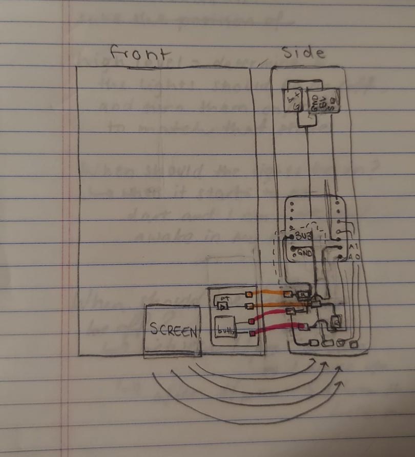
For my PCB I really wanted to use this button that I had gotten from another class (as it had a larger surface area to press, and fit my color scheme). However, I could not find a footprint for it, so I had to manually draw footprints for it by working in illustrator, and editing the svg until I could hold up the button to the screen when it was in actual size and be certain that the pieces could be soldered together. I also wanted most of the PCB to be on the side, but I recognized that some of it would have to be on the front face, particularly the light sensor, and the button, so I decided to make it as 2 modules: one for the button and light sensor, and the other for the rest of the electronic connections.
Sketch of the circuit
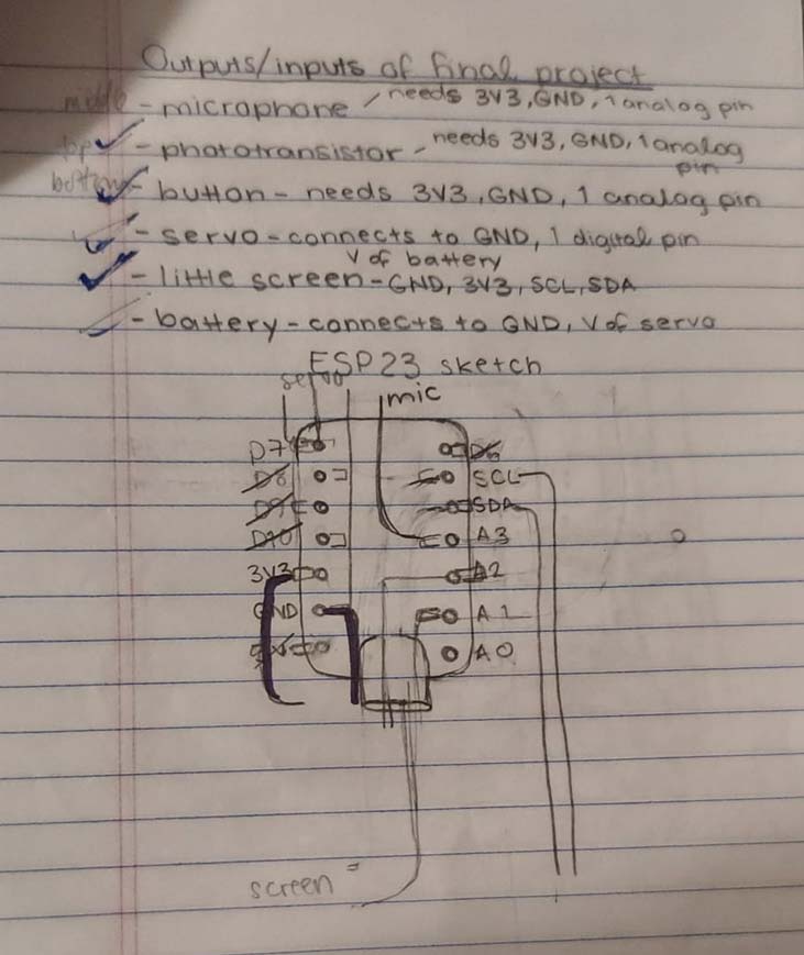
In starting to design the schematic, I also worked out how I wanted to allocate the pins in a quick sketch.
Sketch of pin allocation
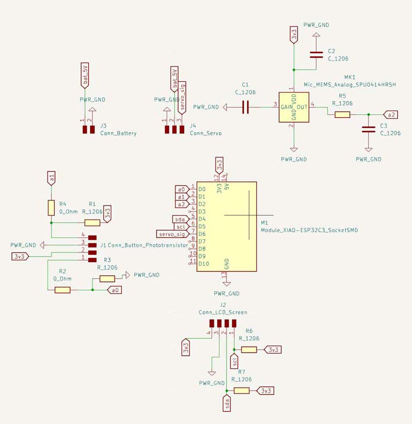
I then translated it to a schematic and then into a PCB. I had to use a couple 0 Ohm resistors to make it all work, but it should not be too bad.
Schematic
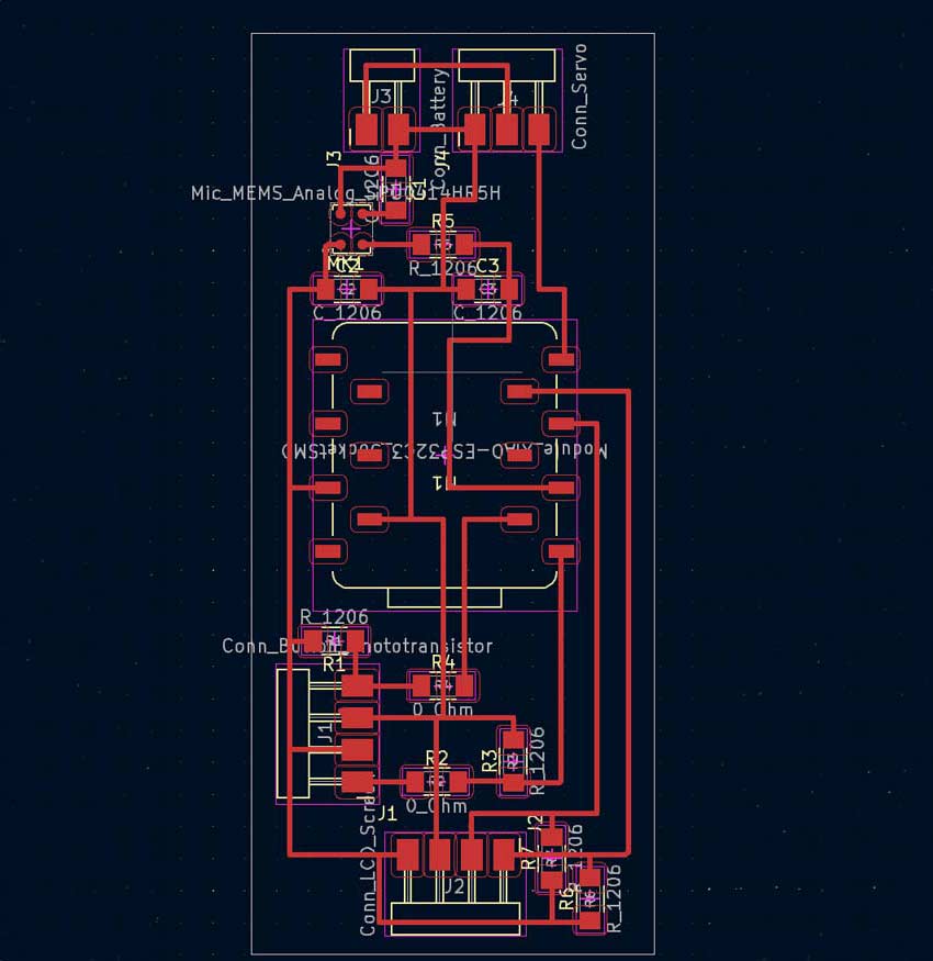
Routed PCB
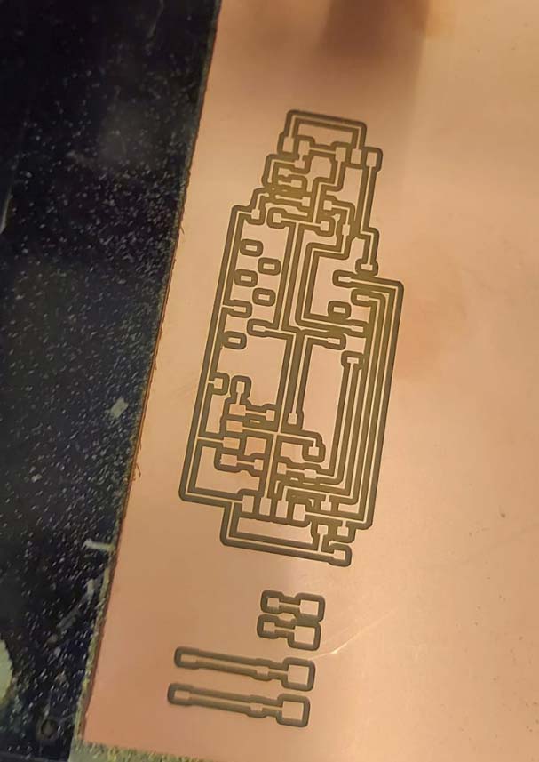
Milling for this project was not too difficult - I had a slight issue where I originally picked a copper board that was too small, but I just re did it and it was fine.
Milled Board
As I was designing the PCB, I wanted to try to see if I could add a microphone, but I did not have access to a reflow oven at the time. As it was not crucial to the design of my object, I just decided to make an attempt and see what happens. In order to solder without a reflow oven, I tried tinning all of the pads on the microphone and the pcb, and then I turned down the heat of the soldering iron in order to attach little bits of solder to the the pads on the microphone. I then turned back up the heat and then attempted to attach the solder to the traces the led up to the pads. This semi-worked; half of the microphone seemed to be soldered correctly but it had soldered while the component was not perfectly in place so half of the microphone was not in the right place. Ultimately I tested the microphone and it didn't seem to be measuring anything, so that might be something to work on for the next time. I then soldered the rest of the pieces on.
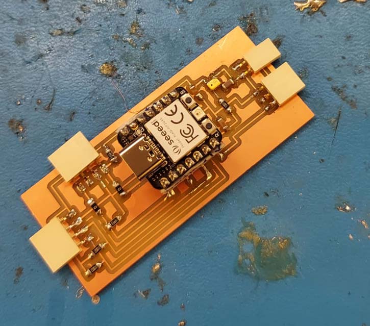
Soldered PCB
After finishing the soldering, my pcb just kept short-circuiting for a bit - honestly I still am not sure why exactly. After a couple minutes it just stopped short-circuiting.
Code
The nice thing about creating the code was that it was truly just a combination of the code I had used starting for other weeks. As such, putting together the code for the final project required me to really practice being organized with my code, as I generally have a tendency to not pay attention at all to the organization of the code so long as it accomplishes the goal I had set out to accomplish. However, if I was not organized in this case, it would be really hard to debug issues and understand where things were going wrong. Nevertheless, as I was coding, I realized that I did not truly have any idea for the implementation of the light sensor so it did not make sense to include it in my final project at this time, especially because I could not get the microphone to work. Initially, I was thinking that the switch should be able to determine if I am asleep and if the lights are on, and then use that to determine that the lights should be turned off. However, in practice, I was nervous that it would not be able to be sensitive enough to my actual needs; I did not know of a way to have it confirm that it should turn off the lights before turning off the lights in that circumstance, and it would be truly annoying to be working quietly in my room just for my lights to shut off. Thus, I decided to turn back to just the button and the webserver being able to act as actuators. First, I set out to make the code in the loop function as simple as possible and conceptualized the pseudocode; while it's waiting for the button to be pressed, the object should display the clock and update it, and check for a device trying to connect to its IP address. If the button is pressed, it should change the position of the light switch, and if a device is connecting to its IP address, then it should display the html and turn on/off the lights if the person clicks the button. As I had worked on these elements separately, it was mainly a question of copying and pasting, and adding things here and there, such as making the display invert when the button was pressed.
Project Presentation Deliverables
Answers to the guiding questions:
For my final project, I designed an attachment for my light switch that could allows me to turn on and off my lights manually and also wirelessly. It is based on something called a light switch complicator that translates torque from the user into . I designed the shell, the fixtures for all of the added components, the sleeve that goes over the batteries, the rack and pinion, and all the PCBs. I used acrylic, m3 nuts and bolts, velcro, bristol board, a xiao esp32c3, copper plates for milling, heavyweight yupo, PLA, a servo motor, batteries and a battery holder, most of which I got from scrap around different makerspaces and projects from previous classes I've taken. As I did not purchase any of the materials myself, I did some googling and the cost estimate is about $60 worth of material in my actual final project. I made the rack and pinion with laser cutting, laser cut the frame for the motor out of metal and 3D printed the shell base. I did a lot of things that I had not done before, so a lot of the questions answered were whether I could do something, and a lot of the time the answer was yes. What didn't work was the microphone; likely because I did not reflow solder the component on, the connections did not work right. Either way, this was not crucial, as I've since realized it would not be that useful for the final project. What did work super well was the rack and pinion - once I turned down the speed of the motor, it had a pretty smooth motion and did not at all slide off of the slight switch or out of alignment. I evaluated the project by just making sure it would turn off and on my lights and maintain an accurate clock if I either pressed the button or used the webserver. One implication for my project is that in the future, if I figure out how to make the microcontroller send push notifications to my phone, maybe I could reintroduce using the light sensor as an actuator, where if the user doesn't reply to the push notification over a period of time, the lights will be turned off.
Demonstration Video In this video, I show the device turning the lights on and off manually, and using the webserver. There were a couple of issues connecting to the webserver for a bit, but altogether it works okay.
Working final project! I cut/edited the video just because the video was a bit long, but as shown here, it works manually and via a webserver.