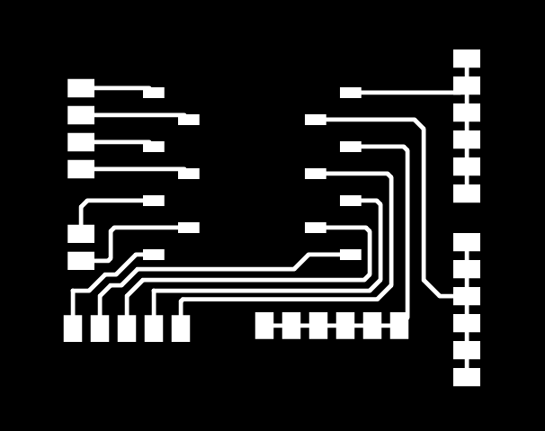
I began this week by milling the board that I had designed last week. With the help and guidance of Simon Lesina-Debiasi, I began by exporting the board as an svg. I was so happy to do this because anything that allows me to use Adobe Illustrator makes me happy. Preparing a file for the Modela is pretty simple - you start by shrinking the artboard down to a little larger than the size of the board. Then, you make the outline filled with white, and give it no stroke width. Then you export the traces without the outline as one png and the outline itself as another png (when you export the svg out of KiCAD, the traces and board outline should be on separate layers, which makes it easy to separate). As I saved the two, I made sure to name the files according to which one was the traces and which was the one for cutting out the board. The traces can be seen below.
PNG for Traces
Milling the Board
For milling the board, I used the archshop's Modela SRM-20. I began by referring to the size of the artboard to determine that my board would fit on the copper that I had picked out. Then using double-sided tape I attached it to the spoilboard in a flat-enough area.
Blank Copper Piece on the Spoilboard
Following the instructions of the archshop website, I put the 1/64" endmill in pretty deep into the collet, and then tightened the screw until the endmill was just snug. I then used the mods page to move the head of the machine so I could set X and Y as 0 at a good spot. After looking both head on and from the side, I felt that it was in a good position. However, upon loosening the set screw and then setting the endmill at the surface of the copper, I realized that the X and Y was not exactly where I had intended it to be, largely because of my depth perception was off, although my board would still fit. After that, I calculated the paths in mods, and sent it over to the Modela to mill the traces.
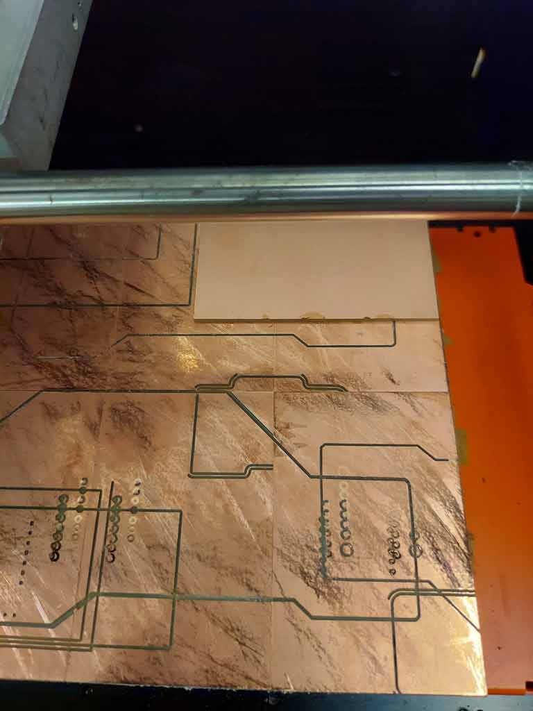
Milling the traces on the Modela
Thankfully, the traces came out super clean, so after vacuuming I uploaded the png with the edge of the board. I then put in the 1/32" endmill (after carefully putting the 1/64" endmill away), and set the new Z = 0. After that, I calculated the path, and milled again.
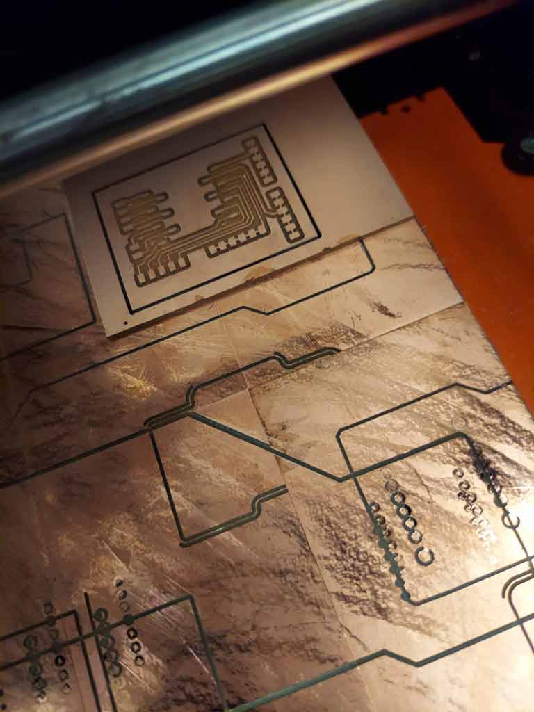
Fully milled and cut board
LED - Button Module
Of course, another part of this week's assignment was to make sure that your board works, so I decided to design a small module comprising of an LED and a button. As I still have the possibly irrational fear of the board electrocuting my computer, the basic idea was that the board would have a space to read the voltage so that the microcontroller could read a button press in a future application, but also would turn on an LED when you press the button, so that I could be sure that current was flowing without having to risk my computer as the voltage source.
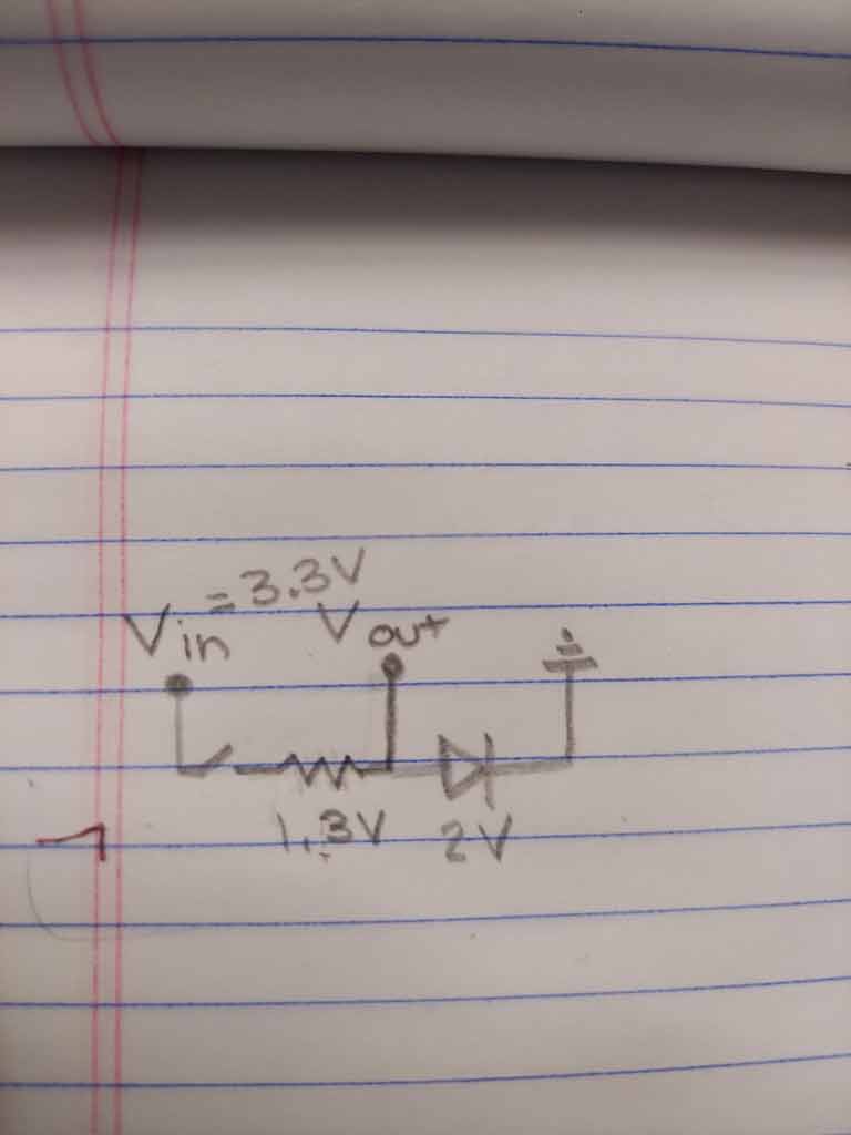
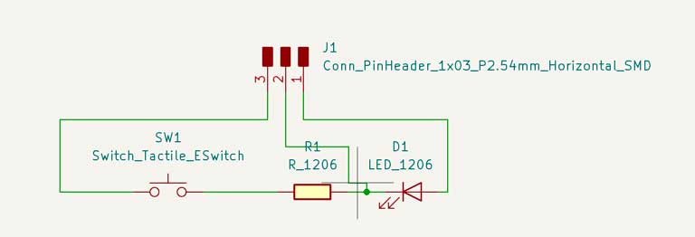
With this in mind, I drew out how I expected/wanted the circuit to work.
Sketch of the circuit
I knew that I would need a resistor so that I could measure the voltage drop across the resistor and use that as an indicator as to whether the button has been pressed. However, I was not sure at all as to what the resistance of the resistor should be, so I just figured I could pick one as I did the soldering. Altogether, moving from the schematic on paper into KiCad and then making a PCB was pretty straighforward because there were so few components to worry about.
KiCAD Schematic of LED-button Module
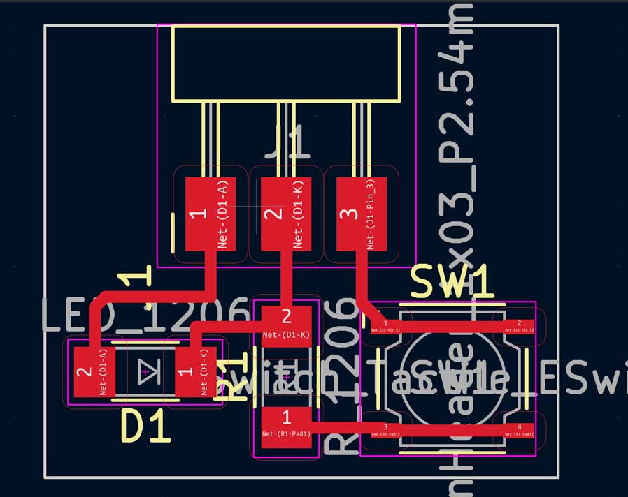
PCB Design for the LED-Button Module
After finishing the design, I went to mill. Every time I mill I find I am really not good at setting X and Y at a good spot so I don't waste material. I am not sure why but everytime I finally bring the end mill down to touch the material it is much further from the edge than I mean for it to be. I'm sure it's something about my glasses and overall weak depth perception. Altogether though, it came out pretty clean and I moved onto soldering!
Soldering/Stuffing the boards
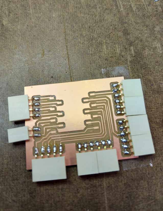
While I have soldered before, I have never soldered with such small components. Following Niklas's advice, I washed the PCB and then made sure to allow the solder to flow onto the copper first, then place the component on top, and then melt the solder to help put the component on place. This worked somewhat inconsistently, as sometimes when I was melting the solder to put the component, it would move out of place. I imagine I will get better with practice though. Using this process, I was able to do all of the soldering for the breakout board for the microcontroller. When I first started soldering I realized that I did not have my microcontroller with me, so I was unable to solder the connectors for the the xiao at the time of the picture below. Learning to solder with the connectors was pretty nice as they have relatively large pads compared to some of the other microcomponents, and this was a nice warmup for working on the button module.
Soldered Microcontroller Breakout Board
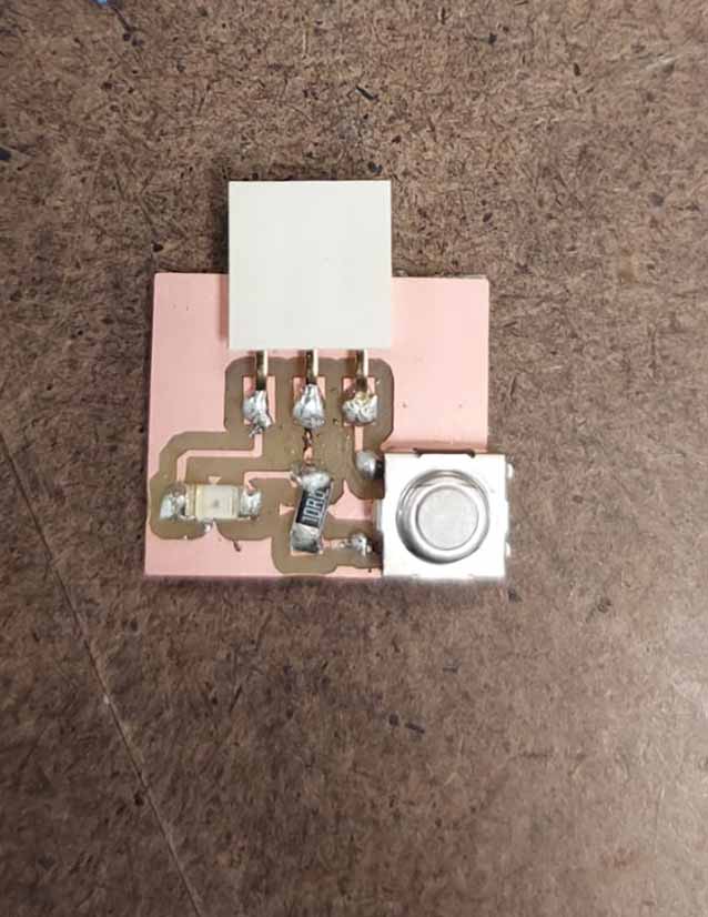
Working with the second module board was a little harder. First, I couldn't get the button switch to sit on the board exactly where it was supposed to be, so I just had to rely on the idea that the two pads of the button are already connected internally, as there was no way that I could make them fit with my limited soldering prowess. I also had to look up the polarity of the LED, which indicated to me that the green line was the indicator of the cathode (so the current should flow towards it). Altogether, it was not my best work (and I also forgot to wash the PCB and I feel like I might have been using a different solder).
Soldered LED-button Module Board
Testing the boards
Nothing is more stressful than testing the board to make sure that it works. Especially because I wasn't completely certain about the size of the resistor, or whether the polarity of the LED was right. Although the goal was to determine whether the breakout board works, it was also possible that the module itself wouldn't work. Thankfully, it worked!
Module Demo
I did notice the LED was really bright, so I probably should have used a larger resistor. Nevertheless, I checked all of the 3V3, 5V and GND ports and they all worked! Another note, is that the nice thing about these white female connectors is that you can write labels on them so that you don't have to continually go back and check which wire goes where.