This week I was really excited to learn about how to make an OLED screen work, so that is what I set out to do.
Designing and Creating the Breakout Board
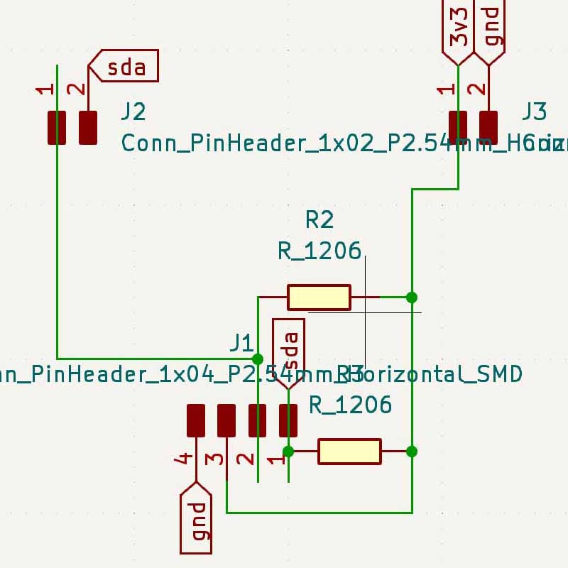
First, I realized that there wasn't a footprint for the OLED screens, so I thought that I would have to do some image manipulation based on what Neil included on the website as his traces. Then, instead I realized that his PCB design included holes that needed to be drilled, and I had no interest in drilling holes in my pcb. So, I then scavenged through the archshop looking for something that could serve as a horizontal to vertical connector, and then something that could convert the vertical connector into a female connector, so that I could put the OLED screen into the slot. In hindsight, it would have probably just been best to go to the EECS shop and figure stuff out over there. However, I was already in the archshop and I was committed to ensuring that I could get it to work without having to find different pieces. Upon finding all the connectors, and making sure that they would all be connected properly, I decided to implement this design into a PCB where there would be a 4-pin connector that I could just use jumper cables to connect to the actual screen. I looked a lot of Neil's schematic in order to determine what had to be included, including some pull-up resistors on the SDA and SCL lines.
Board Schematic
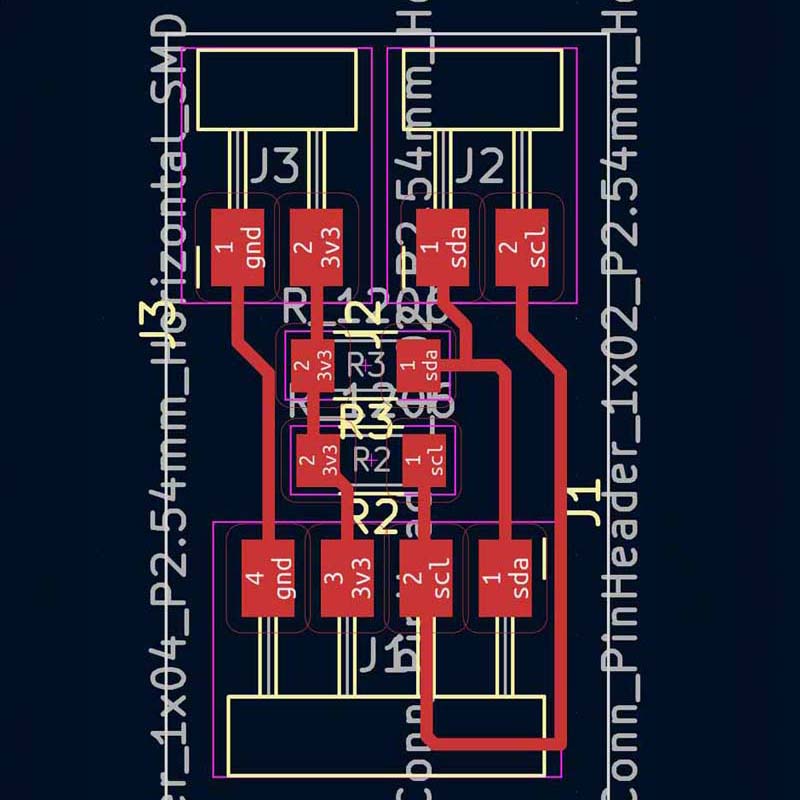
PCB Routed in KiCAD
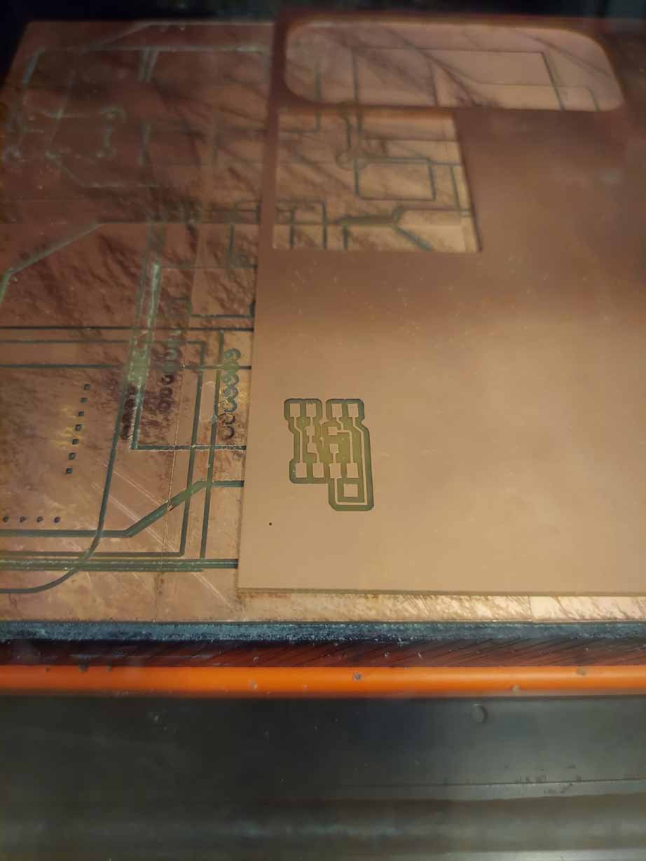
After designing the PCB, I went back to my friend the milling machine to make the board for the OLED screen. This went off pretty much without a hitch, except I had to take some extra time to connect the machine to the computer. I was pretty careful in selecting the endmill to use, making sure that it was not at all broken, and that paid off a lot.
Milled PCB
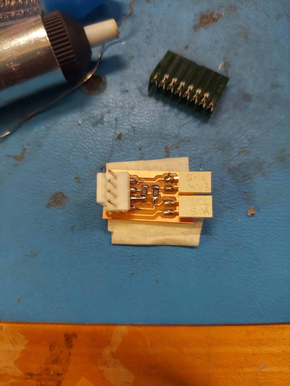
After that, it came to soldering. I felt that the solder was not flowing as I expected, but I did my best to make good solder joints. I think it may have to do with either the solder I was using or the temperature that I was soldering at, as I usually just use whatever temperature that the soldering iron had been set at before.
Soldered PCB Board
Connecting to the OLED Screen & Troubleshooting
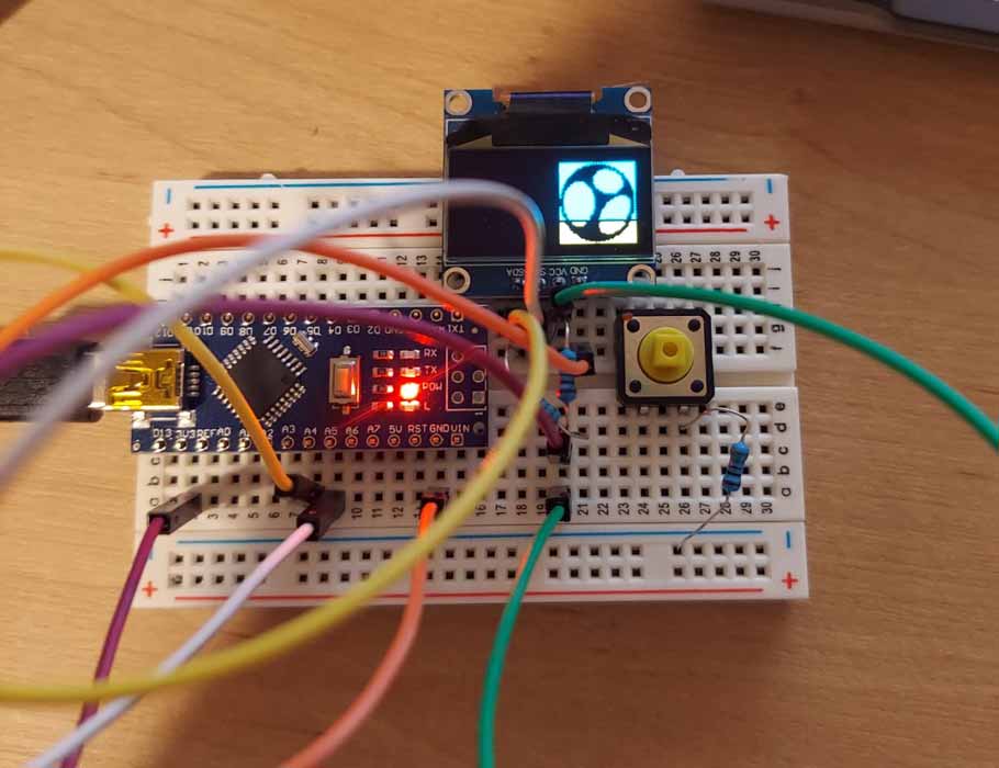
After finishing designing the PCB, I tested all the ports of the module to determine whether it was actually stable enough to carry an electrical connection. As I was away from a multimeter, I simply used my little LED-button module, and was able to confirm that although the setup was a bit janky, it was still electrically connected. However, when I tried to run some sample code for using the OLED screen, the screen simply would not turn on. There was a good deal of difficulty in determining what was the cause of the issues; the code I was using or the screen, or the board itself. I then began to test whether the OLED screen itself was faulty, as I attempted using a different one in place of the other one. Unfortunately, switching out the screen did not solve the problem, so that was quickly determined to not be the cause of the issue. As I was pretty sure that everything was electrically connected properly, I then started trying to determine if there was an issue with the graphics library that I was using in Arduino. The sample code that I was trying to use was from the Adafruit Graphics Library, and I was not sure if there were issues arising from the fact that I was using an RP2040, and using I2C and not SPI to connect with the OLED screen. I tried out a different library to ensure that it was not a coding issue, and tried using the U8g2 library but that did not change things, so I turned to asking TA Anthony Pennes what to do. He said that the graphics library should work fine, even when it is directly connected without the pull-resistors. As such, I abandoned the board and just tried connecting the screen directly to the microcontroller via a breadboard and it finally worked. It seems like there was definitely something wrong with the soldering of the board I designed, but that's something I will solve another day because I could get it to work without it.
Example Code Animation from the Adafruit Graphics Library
Writing Code for the OLED Screen
Once I had finally gotten the screen to work, I decided to play around with the beginning code for the screen so I could figure out how it works. As a first task, I decided to figure out how I could have it display the favicon of my website on the screen. Using this website's code as reference, I put my photo in a bitmap generator, and then replaced their photo with mine, and the code worked.
Working OLED screen with my website favicon
Secondly, this website also provided code for how to make the OLED display show an animation. First, I made the basis for my animation in Illustrator, creating each individual frame. Then, I turned each frame into a bitmap, and inputted the bitmaps into the code and voila, I made the screen display a small animation.