Week 8 documentation
This weeks assignment is to "make (design+mill+assemble) something big (~meter-scale)"We will be using a sheet of 96x48x0.5 OSB as stock for the project.
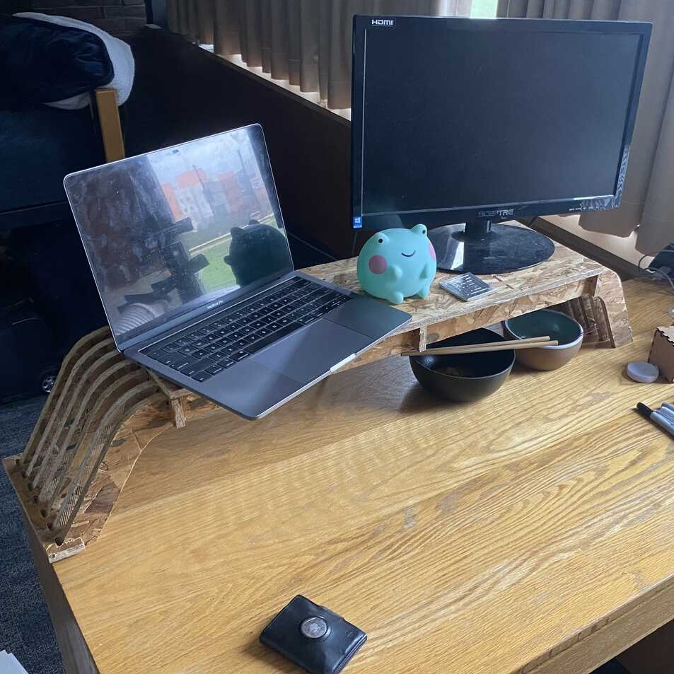
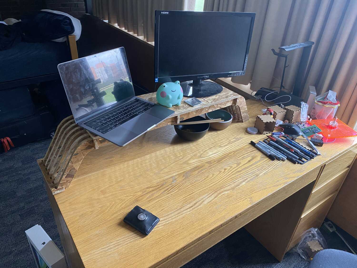
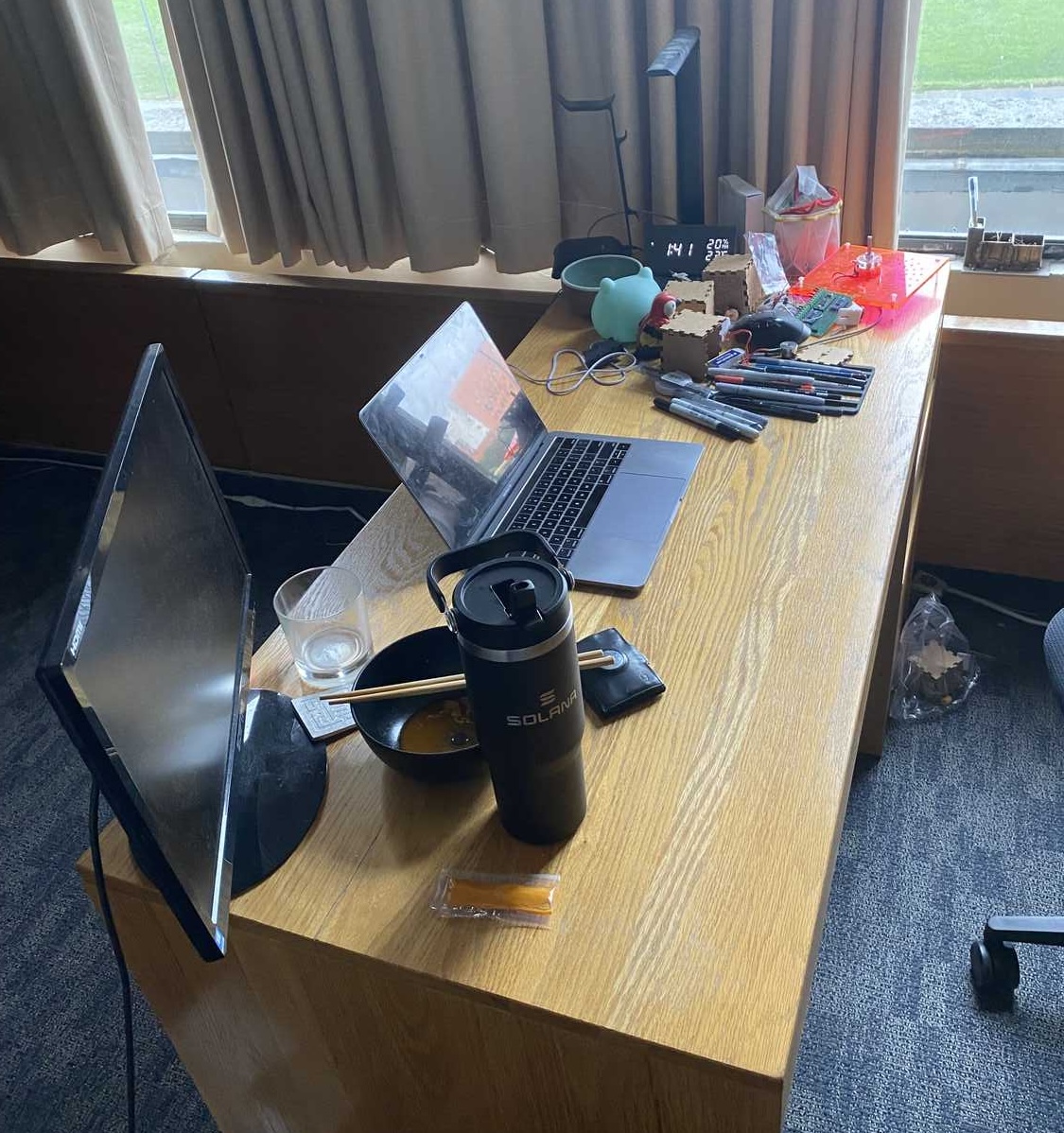
For this week I'm thinking of making a monitor stand for my desk at home.
Lecture Notes
Some project ideas
- making furniture
- chairorigami.com (not practical with osb)
- rigid foam: machines easily
- plywood
- MDF, make signs, very smooth
- MDO much heavier, stiffer, used for highway billboard
Overview
Parts of the projet:
CAD: modeling and creating the machining dxf
Machining: routing the stock materials
Post Processing: sanding, cleaning up, and selecting pieces
Assembly: gluing and putting things together
CAD
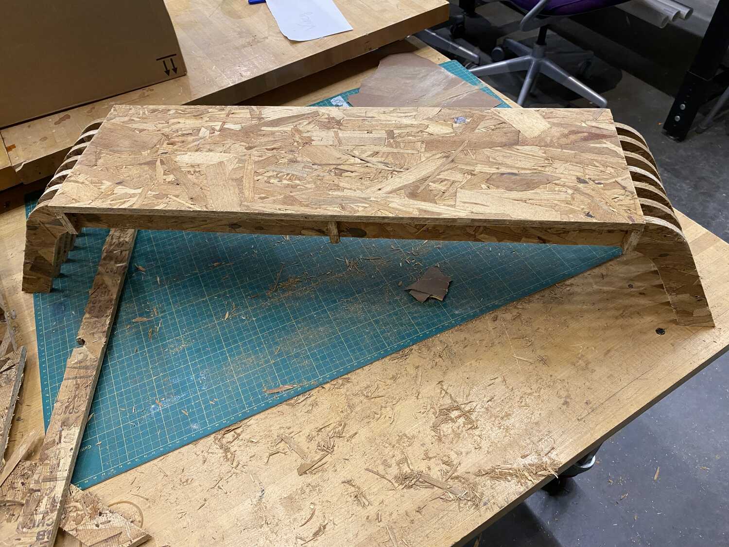
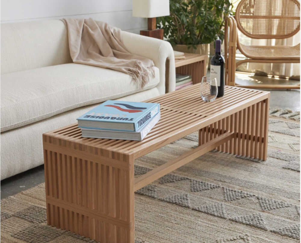
Most of this project was about designing a model. For no particular reason, I was inspired by these funky benches that have gaps in them and decided I wanted to do something like that.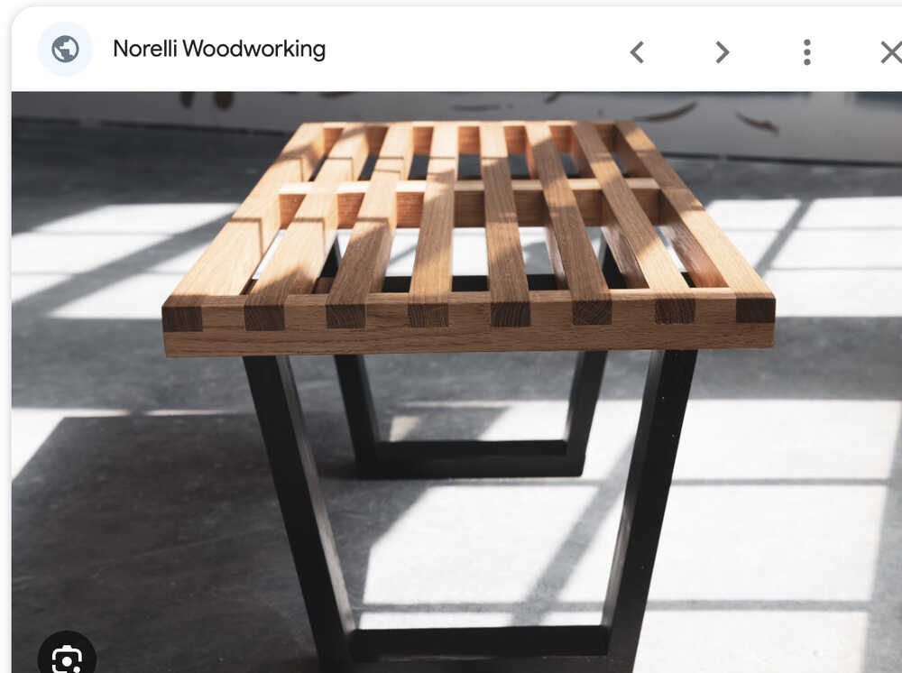
So my I drew an inital sketch:
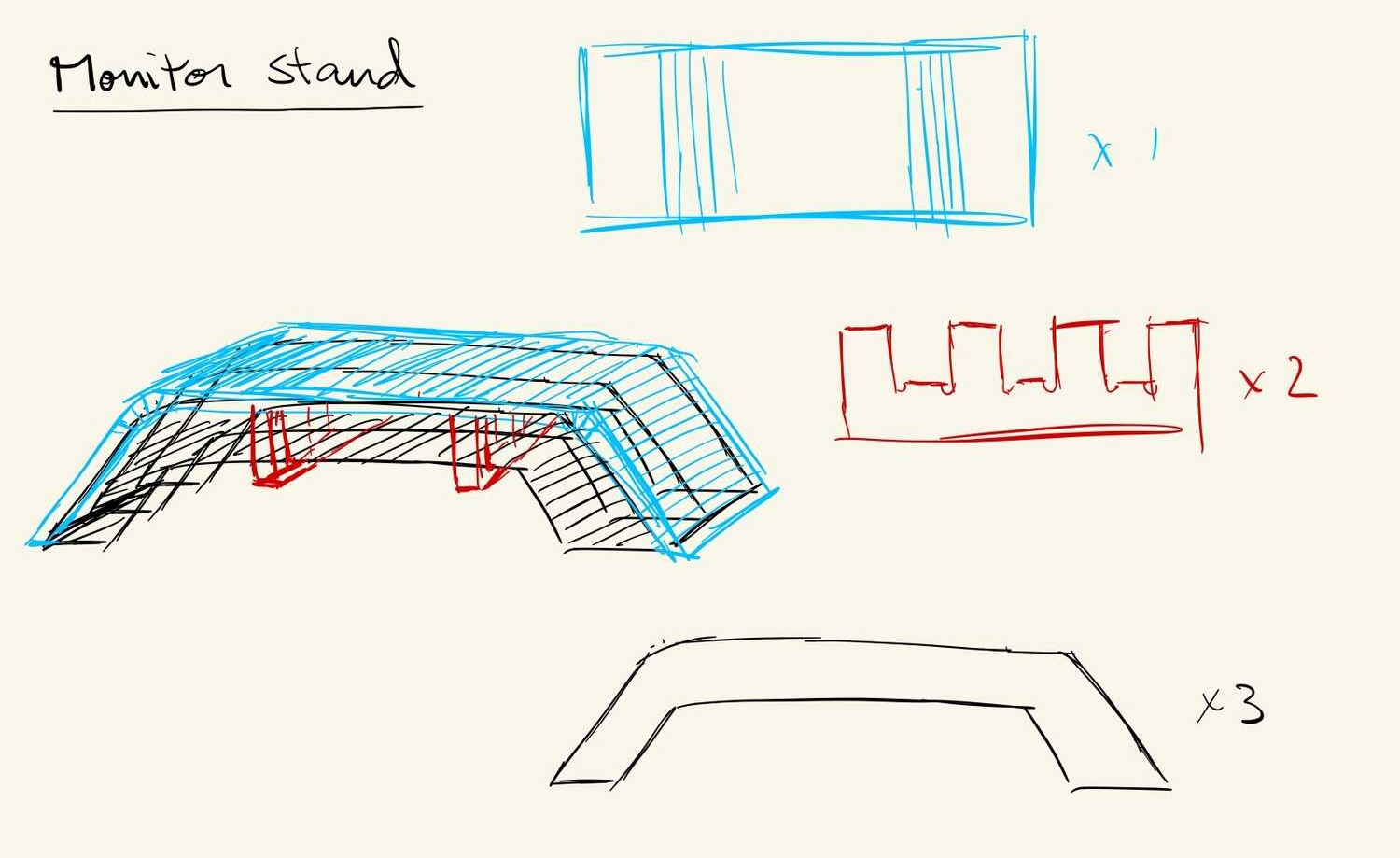
I decided to go simple curved beams attached with a connector and an optional top plate that uses kerf bending to get a smooth curve along the beam. In my final design, I ended up adding grooves to the beams as well, using 3 connectors, and I didn't work out how to mill the kerf bending.
Next, I had to figure out the dimensions and the angle of the bending.
For this stand, I want something that
1. doesn't take up the whole width of my desk, maybe 1/3,
2. that is tall enough for me to stack bowls that I haven't put away yet, and
3. is long enough to fullfill the assignment ~1m (lol).
I want something thats 60cm*(1/3) by 1m by 15cm+beam_width in height. I'm gonna use 60 degree slopes because I don't want the legs to be too spread out and take up space
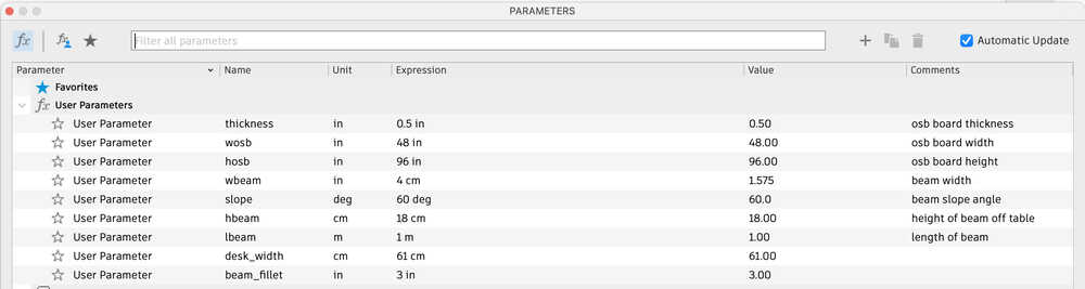
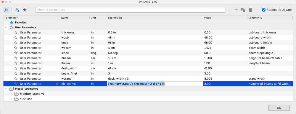
I start my CAD by putting in a bunch of relevant parameters into Fusion under the modify tab.
Sketches
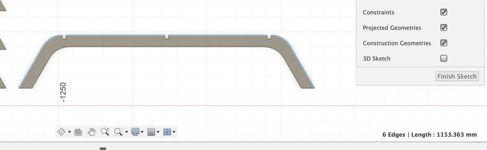
Once that's in I can start sketching out the profile of my beams: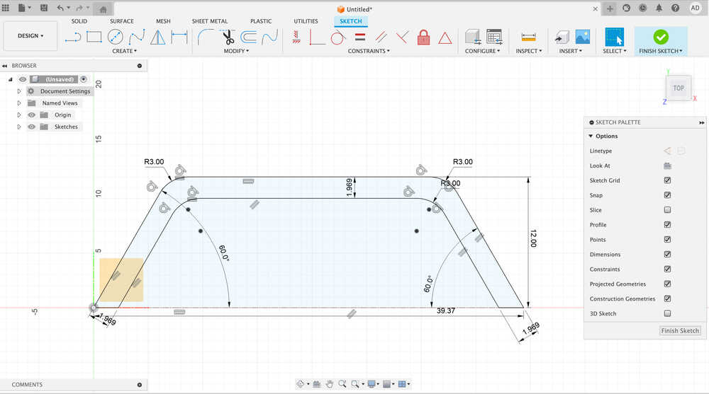
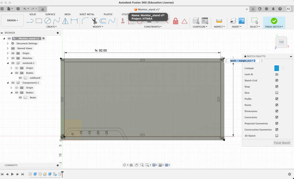
The stock so that I know what I'm working with:
Then the connectors:
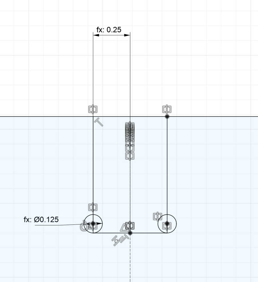
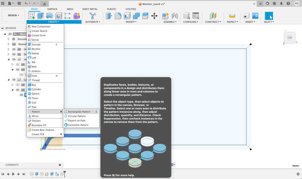
To create the slots, I had to decided how deep I want them to be, which I made deeper for the connectors than the beams since the beams are supporting the weight (and thus would benefit from thicker width) I also added the t-bone features so that they can be milled by a round object. Once I have it, I used the rectangular pattern to have many of them.
A note about rectangular pattern is that it sucks. It doesn't change very well parametrically and I had to manually reapply it many times. To get around it maybe I can create bodies and use the solid rectangular array before subtracting them, which is much more reliable.
Layout
Now that I have these components roughly sketched out, I need to figure out how many I need and to lay them all out. Since I know that my stand will have a width of around 20cm, I can find out the number of beams by dividing it by the thickness of the osb*2 to account for the gaps and -1 to keep things centered.
Before duplicating anything, I need to extrude them so that they are 3D objects and set them up as containers that I can move around for later assembly.

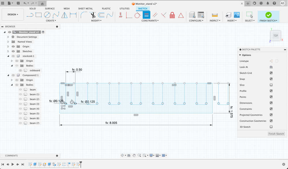
Once these are in place, I create the top boards by calculating the flat length of the beams and then the full length of the top curve.
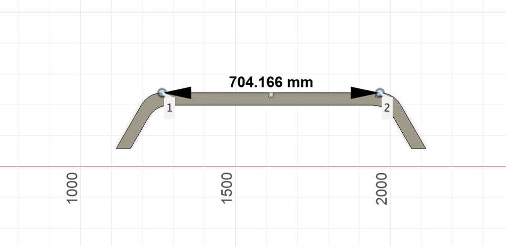
I then use them as a parameter to dimension my rectangle.
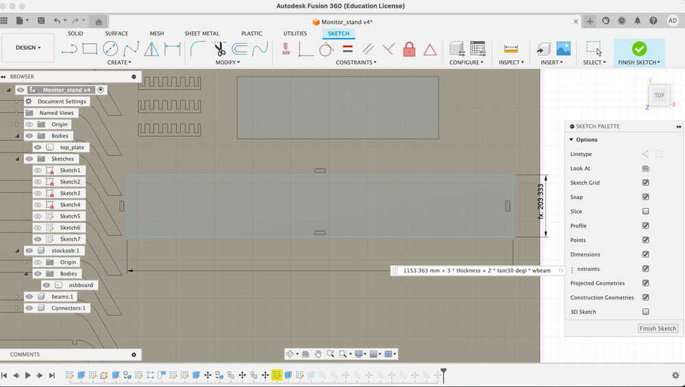
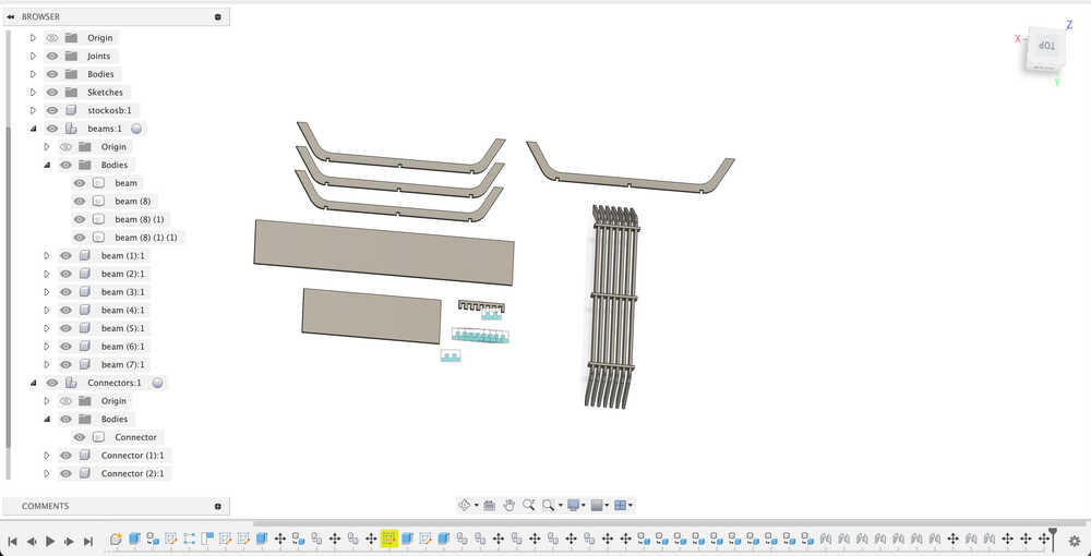
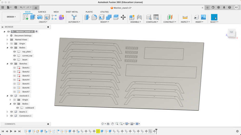
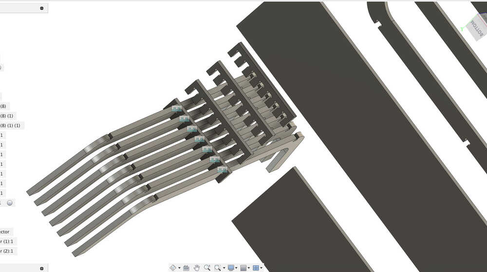
Once these are done, I just copy and move them around to fill in the board and I get this final layout:
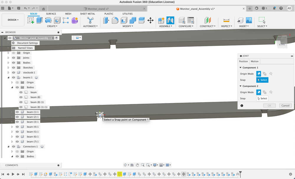
Now on to joints and assembly. Making sure I have all components in seperate containers (joints only work between containers), I create joints between two surfaces of different components that I want to go together.
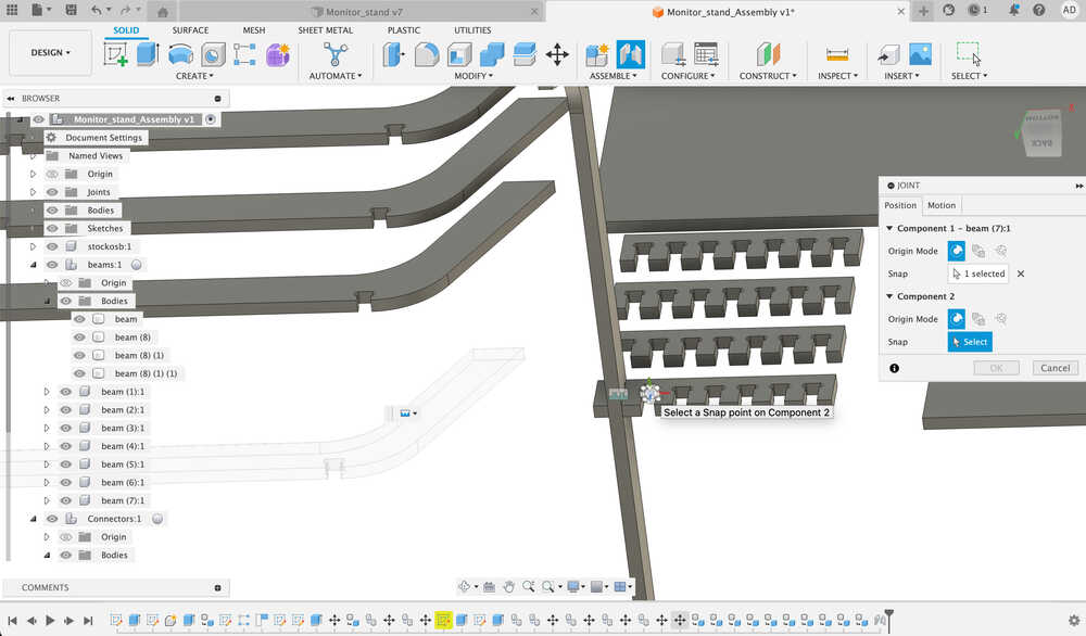
After joining them I need to rotate them into the right position.
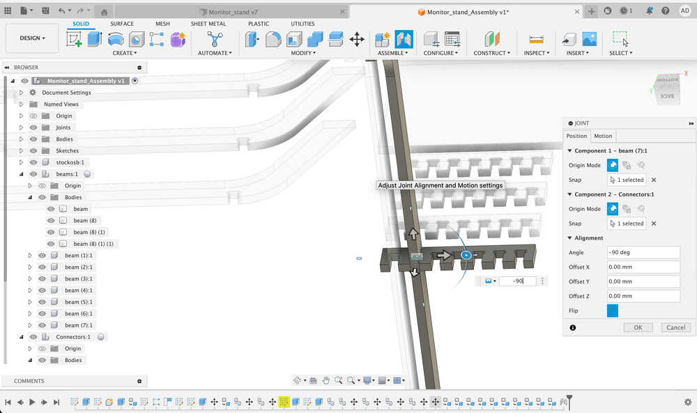
Once all of these are completed, I just need to connect each connector to one surface since its already aligned.
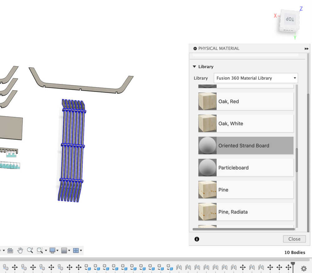
Now, to apply textures and materials in the modify tab. I looked for osb, but only found it in material properties not textures. I decided to just use a plywood texture instead.
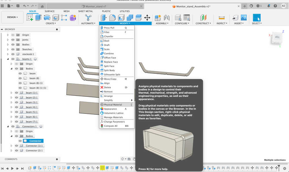
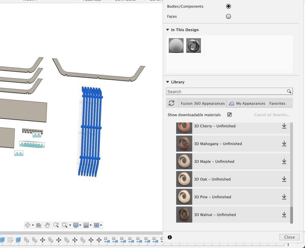
Applying materials:
Now the final layout with the extra piece looks like this:
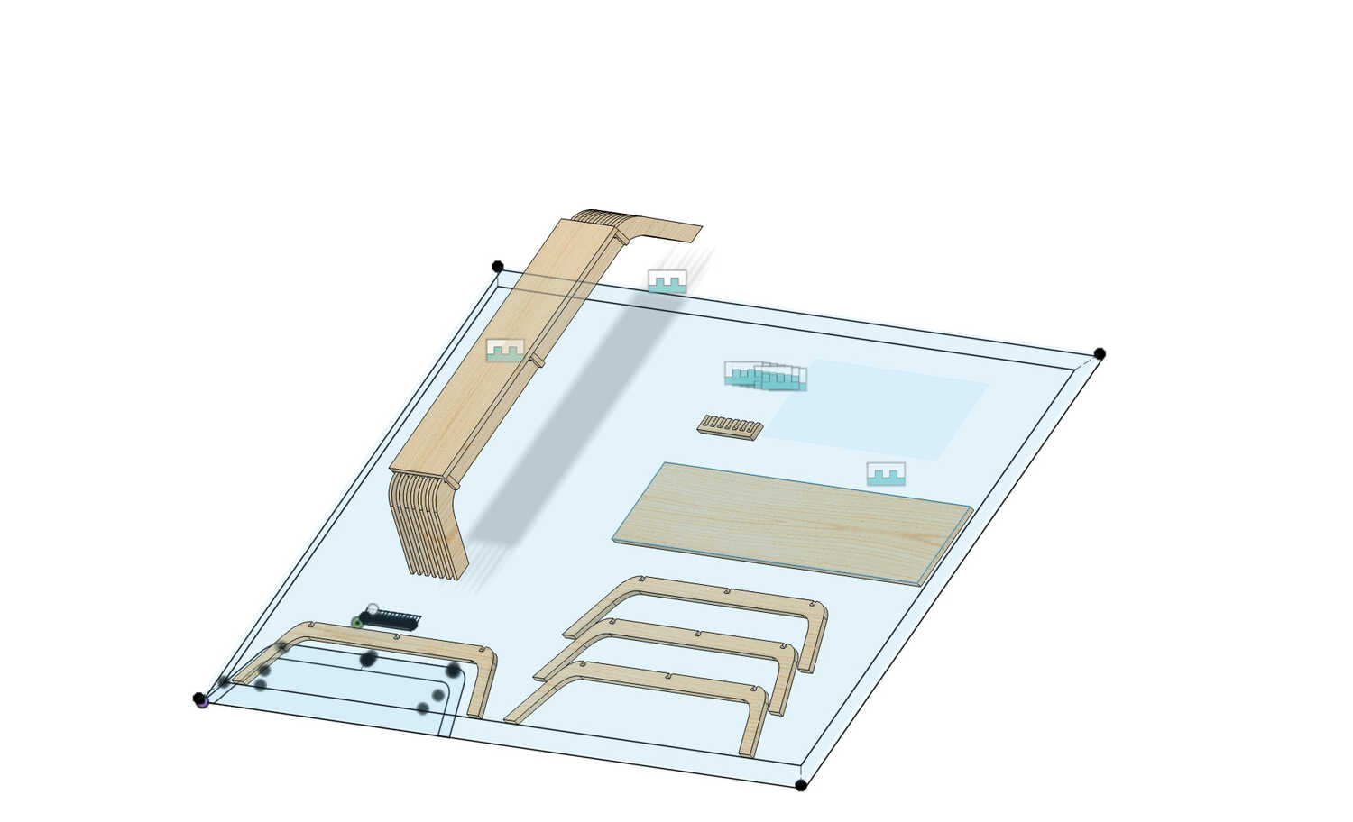
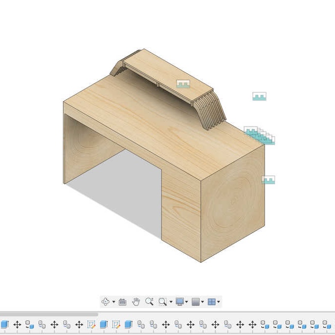
Now that that's setup, I quickly made a model of my desk by extruding a rectangle and some legs, and heres the render.
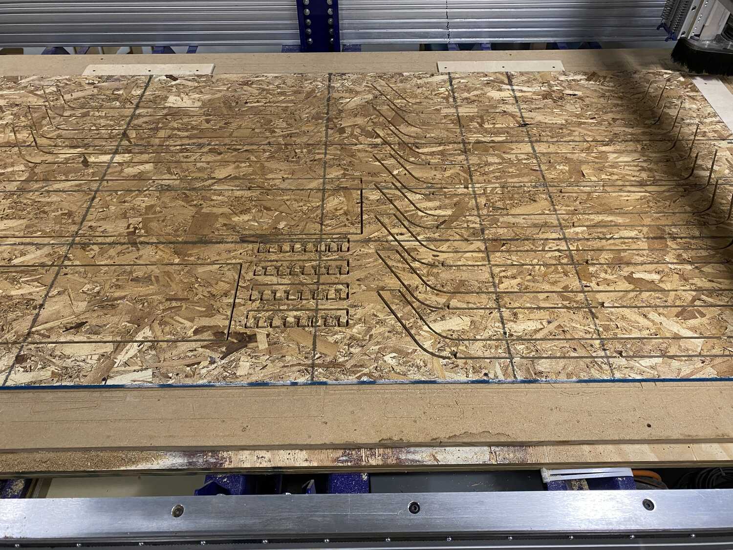
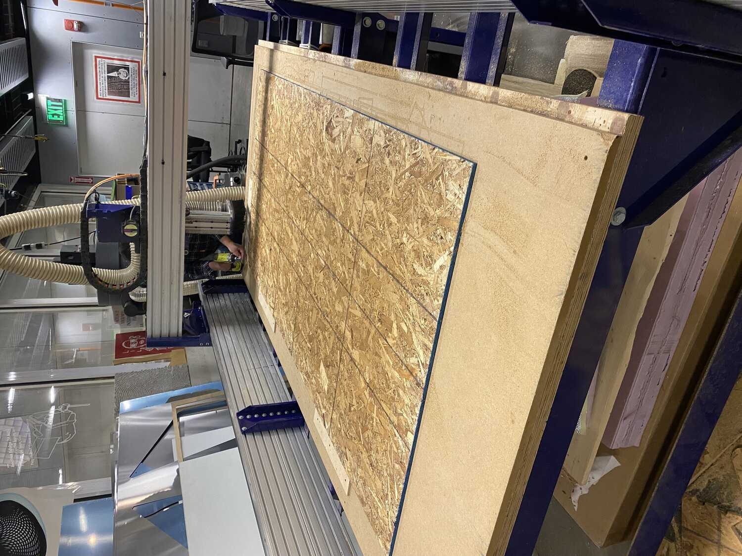
Machining
The machining process was fairly straightforward, but takes a couple steps
- align a sheet of osb to the bed with the centering blocks that John prepared
- add screws along the edge of the sheet
- open in vcarve and edit svg if necessary
- I don't remember exactly the speeds and sizes of the endmills, but it was in John's manual for the week
- jog machine to zero x and y; zero z using macro
- start spindle and then start the job
- turn on vacuum
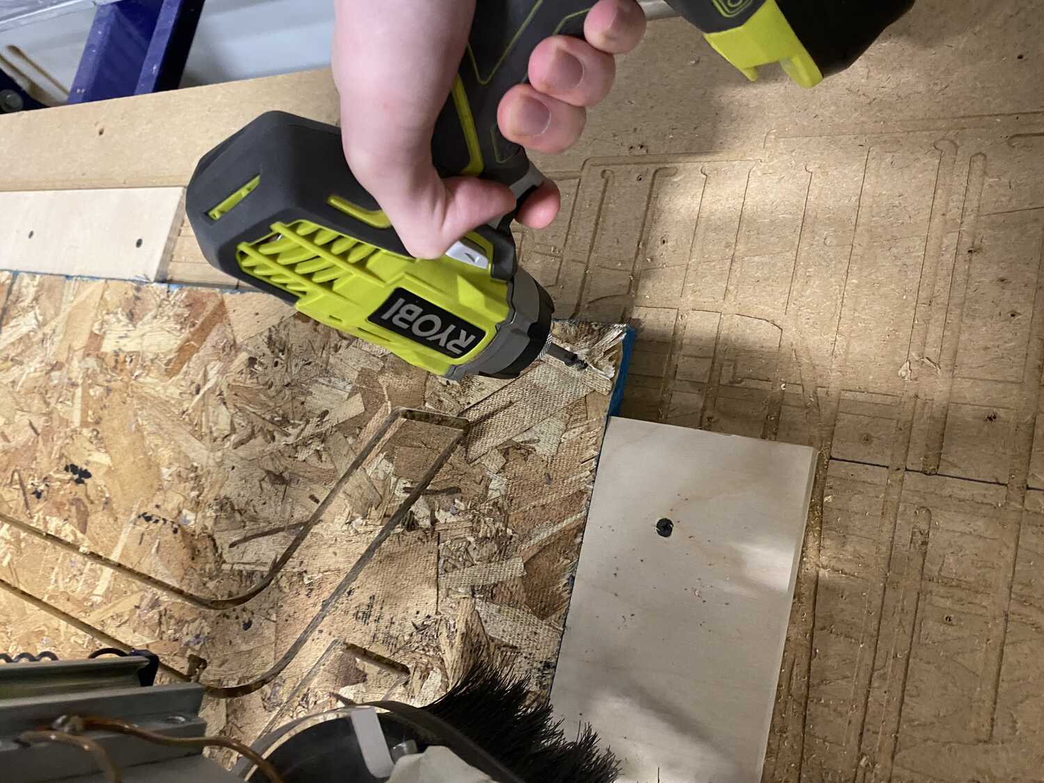
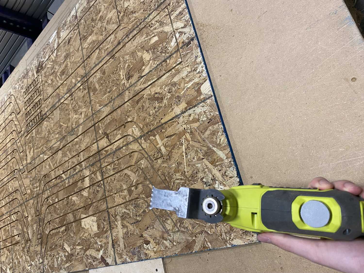
- remove screws and break tabs using the vibrating knife and tool thing
- vacuum all the dust and clear out leftover stock
The machine turned off when the computer went to sleep. While I saved the g-code line and started it up again, it did cut over the piece it was on before for some reason.
Post Processing
After machining, there was still some work left before I can start the assembly. Since the height of the osb wasn't super consistent, there were still a bunch of chips sticking out of the edges of the pieces. So basically I had a lot of sanding to do. I got rid of the tab stumps as well as the chips that stuck out.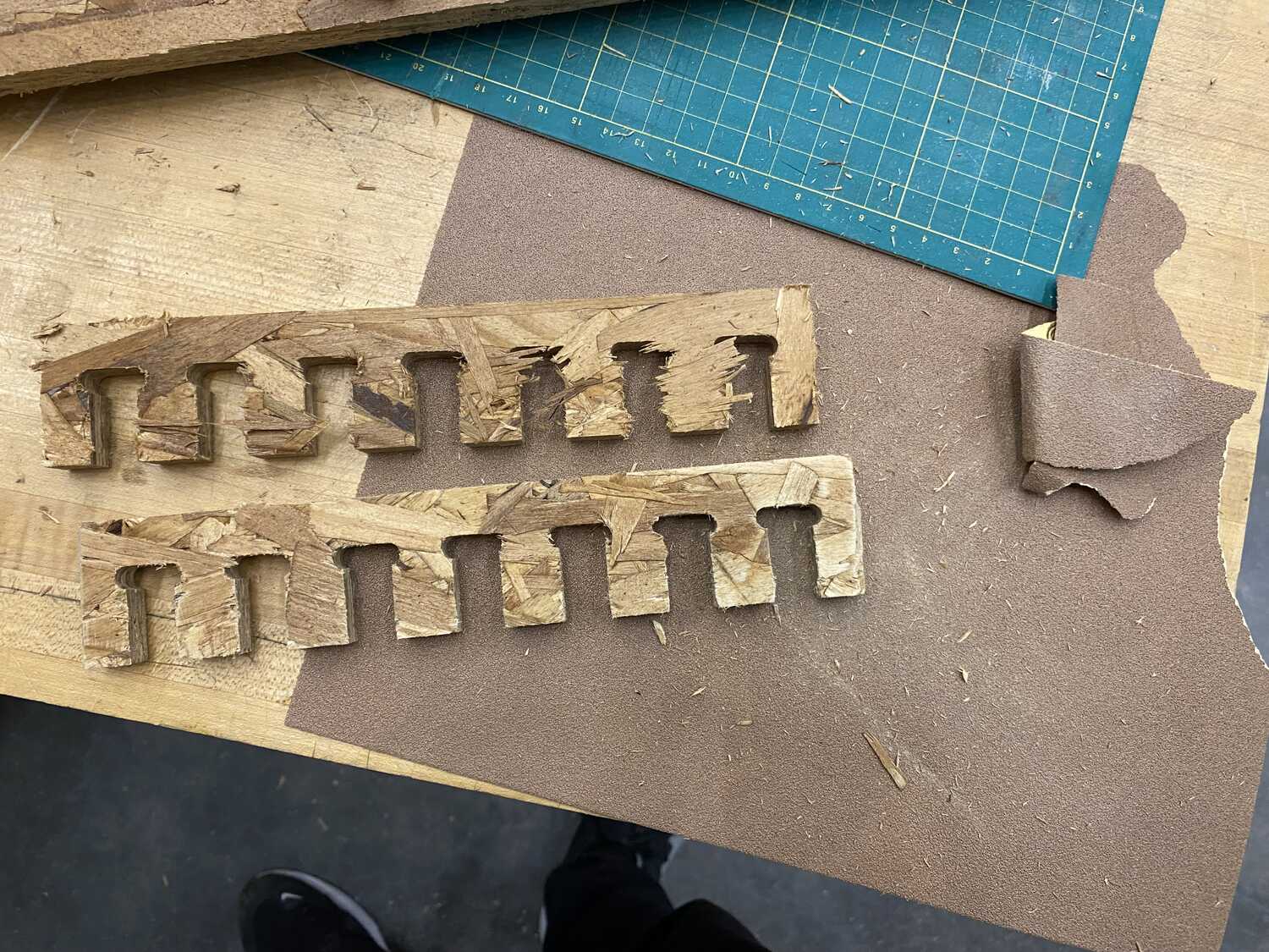
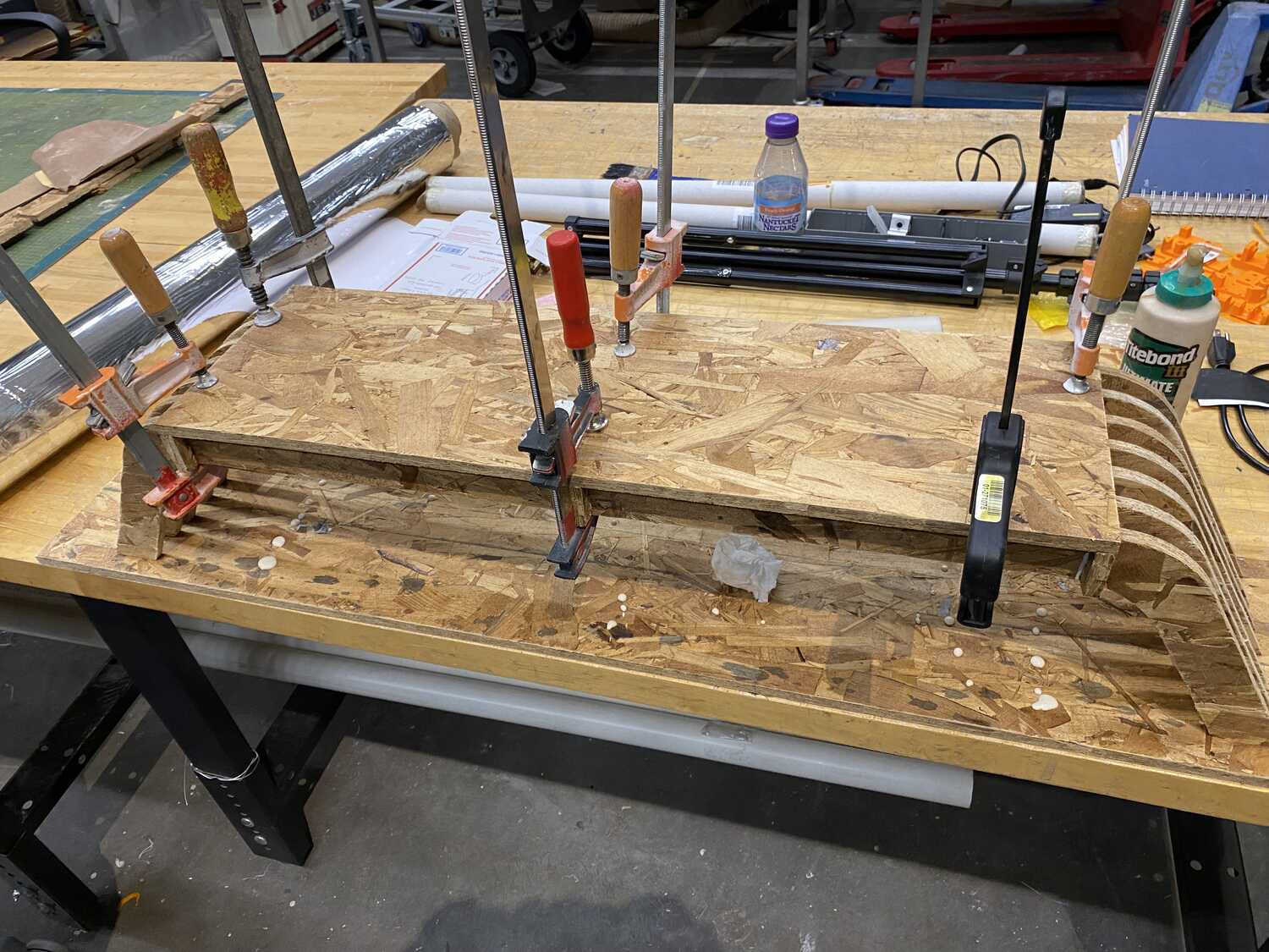
Assembly
Once I had sanded all the pieces I tried assembling them. Since I had used 0.5inch for the osb thickness without checking very thouroughly the tolerances for the joints was not great (the actual thickness was about 0.44inch).