3d print
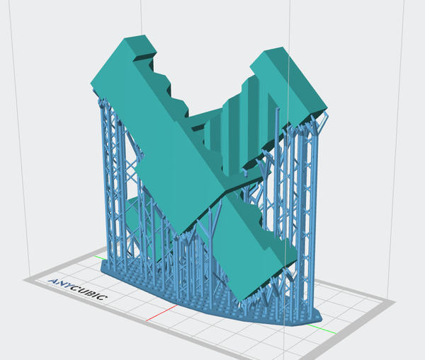
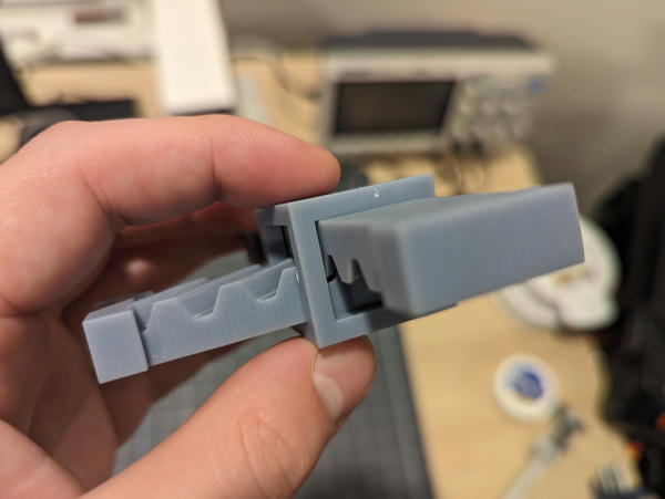
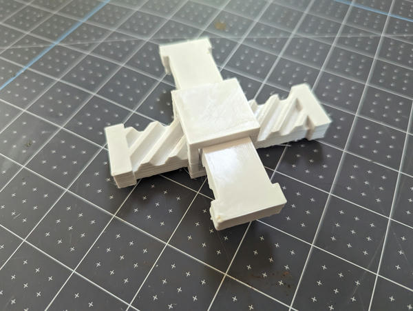
I designed and printed a captive pair of diagonal racks as a fidget toy.
I used my own 3d printers for this week. I both wanted to try an SLA print here (CBA shop training hasn't covered this yet), and be able to take my time/not worry about blocking other people's prints.
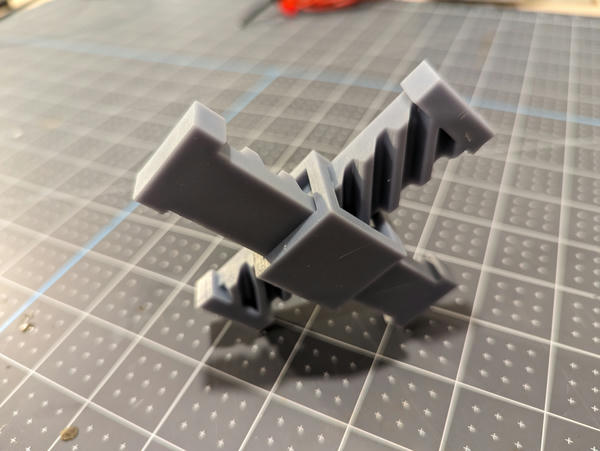
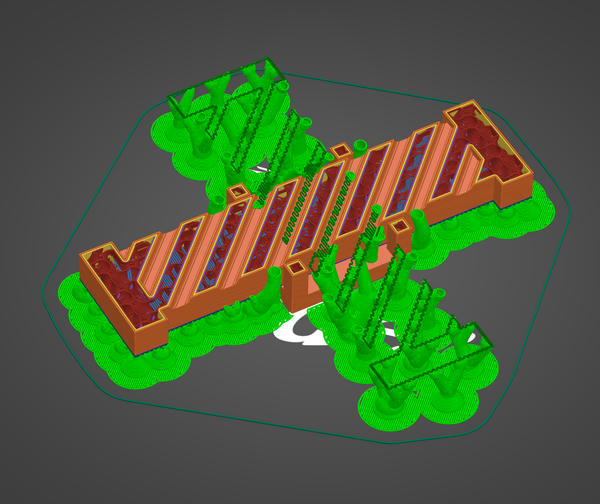
The cage and each rack are separate parts, but the design has them printed in place. The cage slides along both racks simultaneously, and each rack engages with and slides along the teeth of the other.
The design couldn't be manufactured subtractively because the racks are captive in the cage, and the cage is one piece. (Probably you could do this with very careful application of wire EDM, but this design at least couldn't be machined).
Obviously, the difficult part of this is getting the print-in-place to work without bridging the parts together. So far, I haven't succeeded.
attempt 1: sla
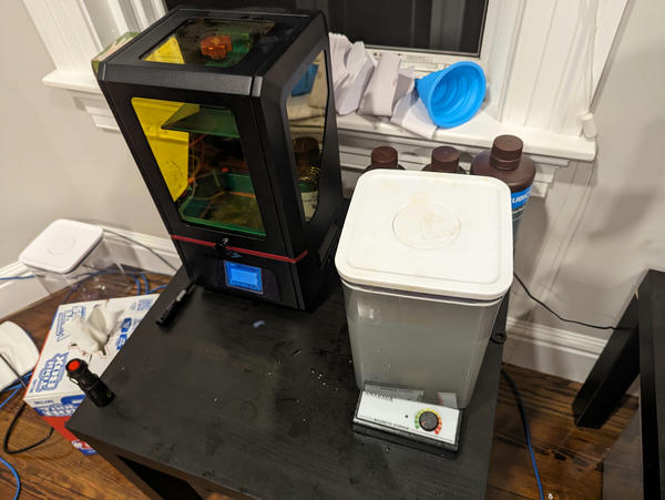
The first attempt was on my Anycubic Photon S with a generic SLA resin I bought on Amazon.
I printed the model at a 45 degree angle with the rack teeth oriented vertically. I was hoping this would eliminate any directional bias / sag due to weight and keep the teeth separate.
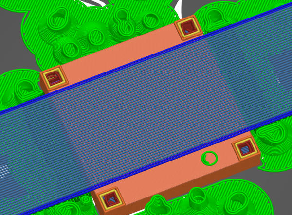
I designed the model with an 0.5mm gap between all the moving elements in order to reduce the chances of unintended bridges between parts. I verified that this gap was correctly sliced into the model:
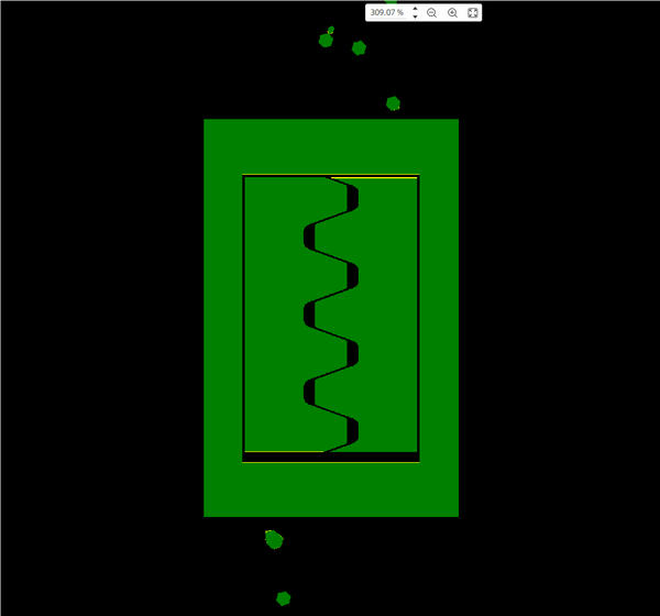
The above image is the core of the mechanism: the cage (outer green ring) containing both racks, which are engaged with each other in this layer. The notable thing is that all the parts are separated by several black pixels, meaning that there should be free space between them.
In principle, I'm relying on the rigidity of the printed structure to maintain the gaps in the model, at least sufficiently that the parts aren't bridged together. Unfortunately, pre- or partially-cured resin is somewhat flexible, and a structure that is intended to be three separate parts has almost no rigidity.
Bow in one of the racks:
The model can also be shifted by the contact with the tank membrane as it is lowered back against the screen.
The printed structure bridged in many places. On this side, the cage bridged directly to the bottom plane of the rack:
Note the top seam is too tight / there is no gap, where there should be 0.5mm.
In this image, we're showing a healthy gap between the side of the cage and the rack, suggesting that the parts may have been free and independent initially, before they eventually bridged:
Rack teeth bridged together:
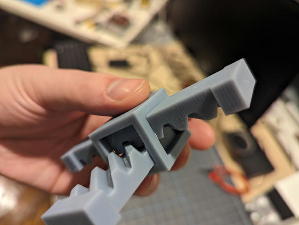
I was not surprised that there was bridging, but I was hopeful that it would be intermittent enough that I could break the bridges and get the mechanism to move. I tried flexing the part and pushing each rack both along its axis and along the axis of its teeth, but I wasn't able to break it loose. I'm fairly confident, however, that both racks are fully or mostly bridged along their back plane onto the cage, meaning it'd be unlikely I could ever get this apart without very involved surgery.
If I were to do this again, I would pre-bridge all of the parts together in a way that fixed and rigidified their intended relationships in the interfacing region. I would design this bridging to be easy to remove and clean up after the fact.
attempt 2: fdm
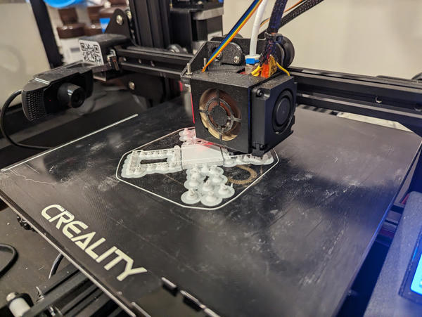
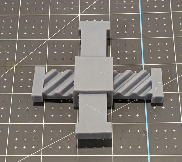
I didn't have time to redesign and reprint the part before class, but I figured I could try the same print in FDM, so I printed the same design (0.5mm separation) on my Ender 3 in PLA+.
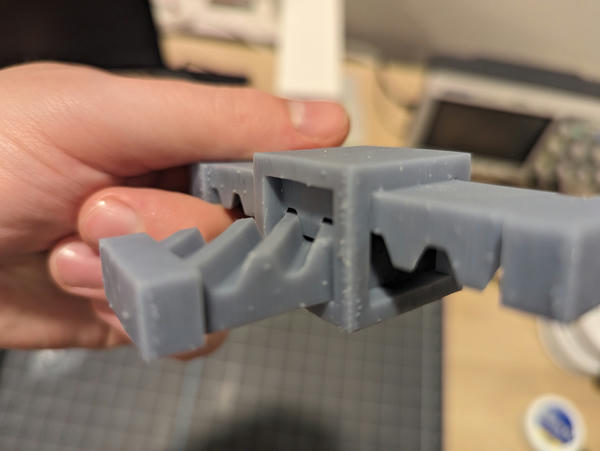
I chose to print with the cage flat against the bed. This required significant manual support painting, as I exported the assembly (both racks + cage) as a single STL object in order to maintain alignment -- PrusaSlicer had no way of knowing that I didn't want parts to rest or sag onto each other.
On reflection, I should probably have printed this standing up, as I think this would have minimized surface area for tolerance-critical supports, though that trades off against a less stable / higher aspect-ratio print.
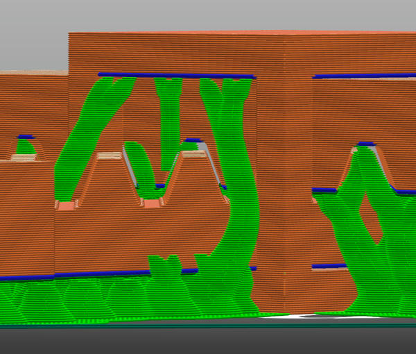
Painted supports on either side of the bottom rack, bridging over the bottom of the cage (cutaway):
I chose to paint support material under the teeth within the cage, which couldn't be supported from the bed. I reasoned that having some low-density material here that could be broken away would be better than potential hard bridges:
Airgap between teeth:
Unfortunately, the bridges here sagged too much and I didn't have my supports dialed in well enough -- I couldn't get it apart.
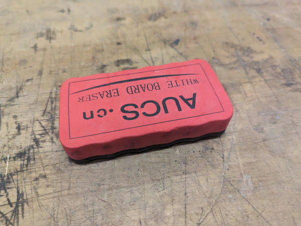
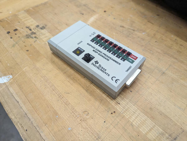
scan
I scanned an eraser and an RS232 programmer with the Leo: