electronics design
I used KiCad to design a pair of boards for my final project. These will be button I/O boards for the MFDs:

daughterboards
First I designed 4 daughterboards, each of which handles one side of the MFD (5 buttons).

Each button is low-passed with a 1uF capacitor and a 10k resistor for debounce. In theory, this should lead to rolloff starting at around 15Hz.
These boards will mount on the backside of the MFD bezel with screws. The hole pattern is TBD based on the final MFD design.
i/o master
I designed the master board based on a Raspberry Pi Pico as a SoM:
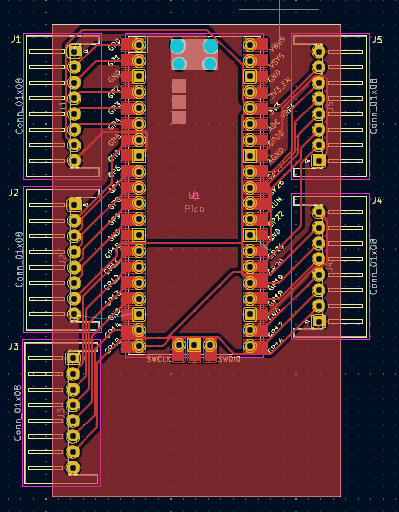
It interfaces with the daughterboards using 8-pin JST connectors, providing 3.3v, 2x ground, and 5x button outputs.
The Pico is soldered to the board using the castellated edge, though I'm considering redoing the layout with a pair of header sockets to make it swappable.
I chose the Raspberry Pi Pico for its high available GPIO count (26 available pins), meaning each MFD can be serviced by one Pico.
I intend to have this board communicate with the host computer using the USB port on the Pico.