input devices
arduino sketch (breadboard pins)
mcu som: rp2040 xiao
Reader Module: HiLetgo RFID Kit
Test Cards: LEXI UID PVC Blanks
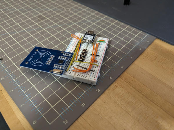
First breadboard version:

Milled board:

This week, I made a reader for Mifare cards (of the type used by MIT) with a COTS 13.56MHz card reader. The reader prints the UID of any card presented to it over serial.
Note that the LED changes color to a darker blue to indicate that it has succeeded in reading a card.
My XIAO board runs a simple Arduino sketch communicating with the reader over SPI, using the MFRC522v2 library.
Sample output when one of the test cards is presented:
read card (sak: 0x08), uid: a5a5a5a5
I have plans to add additional I/O to the board, including supporting multiple modes (such as writing cards), so I included buttons on the board that are wired to unused pins.
There is an IRQ line on marked on the reader module. This is connected as well, and I intend to use it to configure interrupt-driven card reads, though I didn't get to this this week. Notably, it seems to affect the function of the reader if I let it float (detecting card presence when there isn't one), though the documentation suggests it should be an output from the reader IC. I pull it low in the sketch and this appears to make everything work fine.
The RGB LED on the board blinks when it reads a card as feedback to the user, and changes to a different shade of blue once it has read a valid card. It flashes red if the read fails (card moving too quickly).
milling
I didn't originally mill a board this week -- I came back to this later once I had time to get the board milling process right. This and week was done with a breadboard because development was much faster.
Please note: I did design a board for this week to fulfill this requirement -- the design files are available above.