How to Make (almost) Anything 2023 | Week 10.1: Output Devices
Home
Assignment: Group Project -- Measure the power consumption of an output device; Individual Project -- Add an output device to a microcontroller board you've designed, and program it to do something.
Individual assignment: Design an output device
Description: The design, production, and programming of a NeoPixel Jewel 7 output device
Primary files:
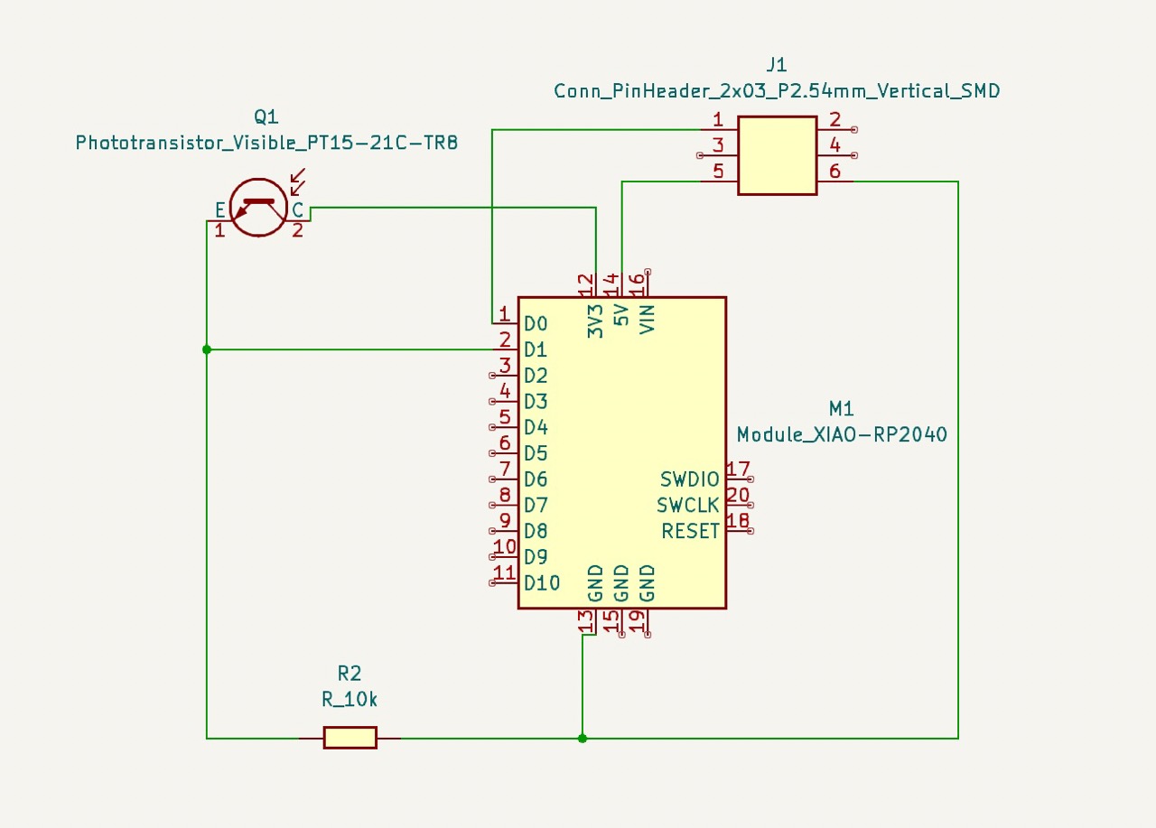
- NeoPixel Jewel 7 output device PCB schematic and design; built upon the Input Device file referenced in Week9.1 (KiCad)
Procedure:
- Design the desired NeoPixel Jewel 7 circuit in KiCad, using a NeoPixel Jewel 7 and Xiao RP2040 (Note: I built this circuit as a new capability to the Input Device from Week 9.1 I, and as such was added to the pin head connectors)
- Once the KiCad file has been made, export as a gerber.
- Import the gerber FCu and Edge Cut layers into Quentin's Grb2Img tool, then select "fill edge cut" and "black and white" before exporting render (Note: it is helpful to do edge cut first and press the lock icon next to the dimensions to ensure your FCu and edge cut dimensions align)
- Import the downloaded PNG files into the Mods platform to convert into G-code (1/64 for Fcu and 1/32 for edge cuts)
- Import the F.Cu G-Code file to the desktop attached to the CNC milling machine
- Prepare the CNC by clamping down a sacrificial sheet of copper (bottom) and the milling sheet of copper (top), then secure the 1/64 end mill using the blue guide to determine proper bit depth
- Move bit to x=0, y=0 and then ensure the ground lead is attached to the top of the probe before zeroing the z plane
- After the z dimension has been probed and raised, remove the ground lead from the probe and insert the plasstic cover over the end mill then turn on the vacuum
- Press play on your mill trace
- Upon completion of the mill trace, turn off vacuum, remove plastic cover, and exchange the end mill for the 1/32
- Upload the EdgeCuts G-Code file to the desktop attached to the CNC milling machine
- Repeat the steps above with the 1/32 end mill for the mill outline
- Upon completion of the mill outline, turn off vacuum, remove plastic cover, and snap PCB from the copper sheet
- Inspect the PCB to ensure the trace was clean and as expected; If complications occurred, adjust design as needed and repeat PCB production
- Solder the respective components onto the board and validate the board does not have any shorts (note: in this instance the connecting cables were soldered to the NeoPixel Jewel 7)
- Within Arduino IDE, program your NeoPixel Jewel 7 to light up specified colors, a delay can also be added for sequential pixel illumination
- Connect the RP2040 to laptop and load the desired program
- Validate NeoPixel output is as expected by referencing the light color and sequence emitted
Key learnings:
- The joy of multicompatibility -- I found the value in designing a circuit with the optionality of connecting additional components via pin headers
- Adafruit has wonderful resources availble -- The Adafruit library was very helpful for documenting the capabilities of NeoPixels
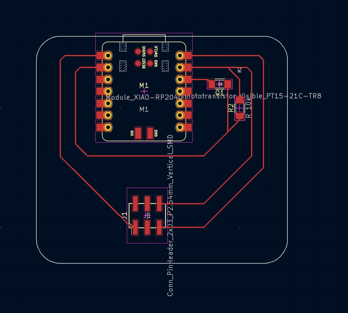
NeoPixel Jewel 7 output device PCB design in KiCad, built upon design referenced in Week 9.1
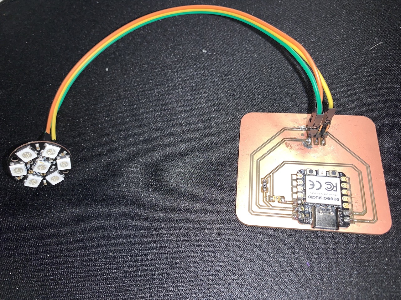
Assembled NeoPixel Jewel 7 output device
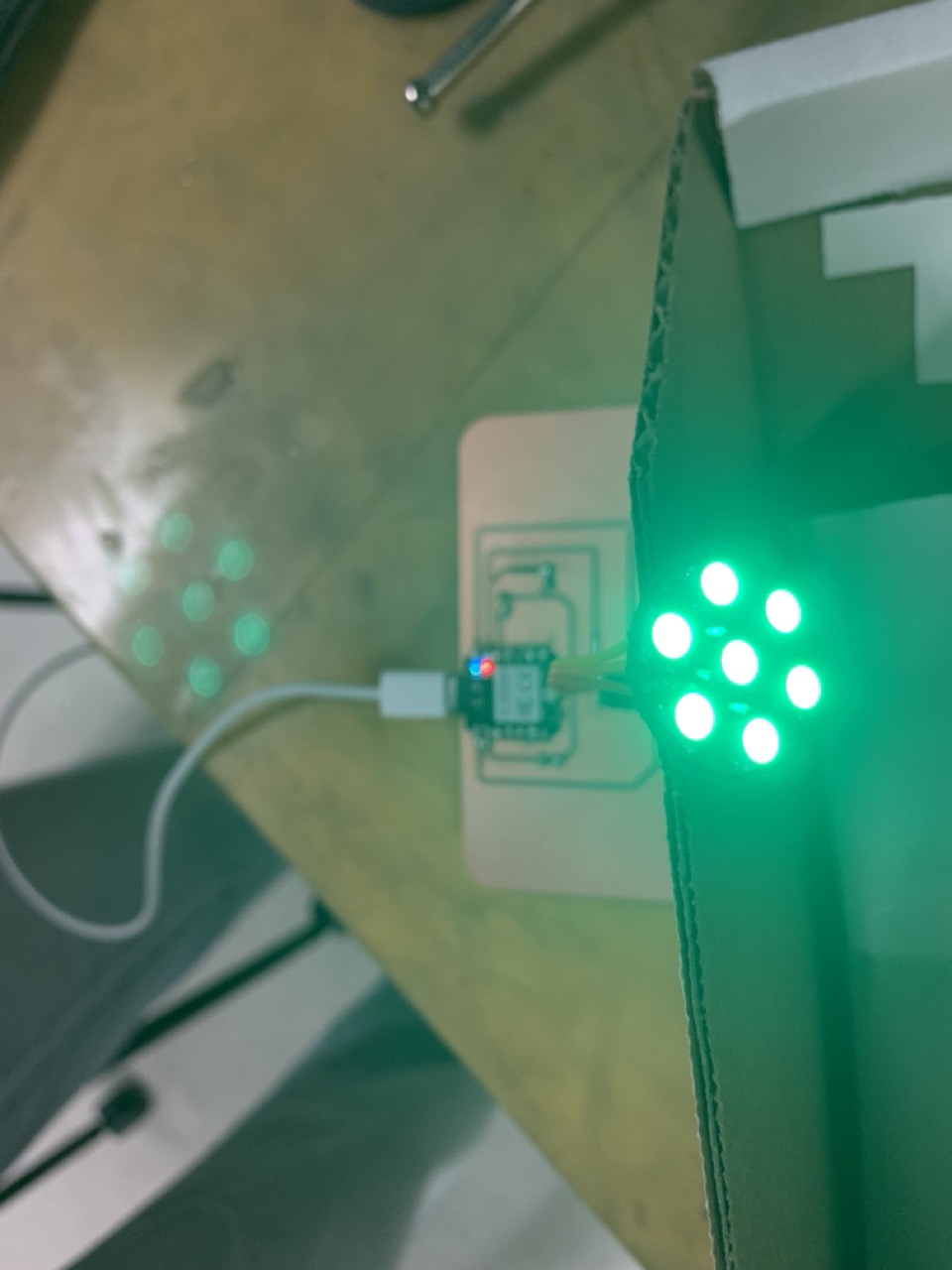
Validation of output device, where the NeoPixel Jewel 7 illuminates based on the specified color and delay sequence