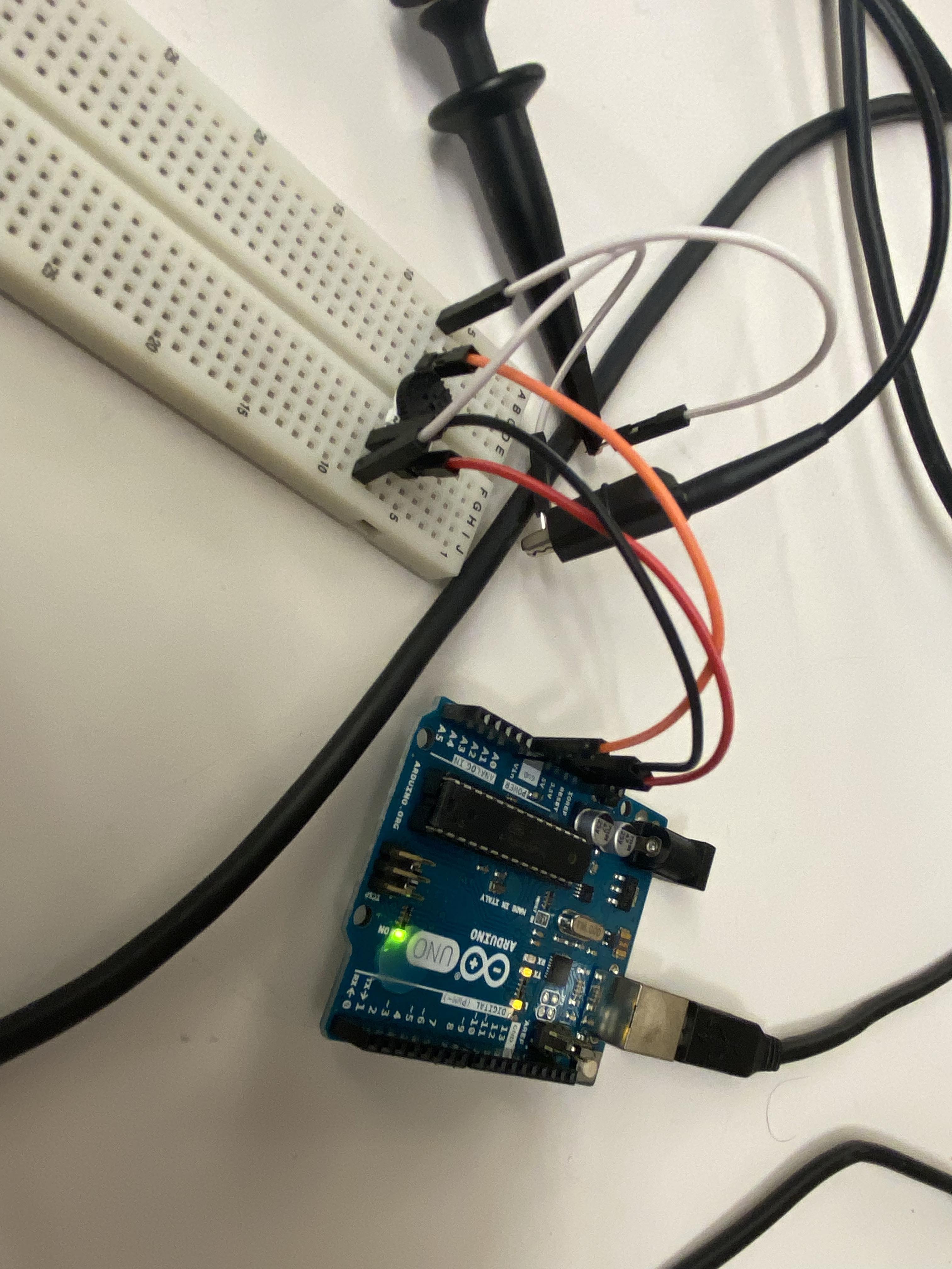
This week, we had to probe the analog levels and digital signals of an input device.
We used a small potentiometer set up with a breadboard and an Arduino. We wired the potentiometer to be an analog input to the board, then used jumper wires to wire an oscilloscope to the ground and analog terminals.
After getting the oscilloscope zoomed out enough, turning the potentiometer with a screwdriver yielded the below result. This behavior lined up with our expectations, as the raw analog reading went up and down as the potentiometer was turned.
Once we re-scaled and changed the trigger of the oscilloscope to see the digital signal, we expected to see the pulse width/duty cycle change as the potentiometer was turned. We did observe this behavior: