Week 10 Assignment: Add an Output Device to a Microcontroller Board you've Designed and Program it to Do Something
My board from last week has built-in LEDs which I already intended to use as "outputs" for my force sensor. Thus, this week was primarily focused on characterizing my sensor and getting the behavior I wanted out of my system.
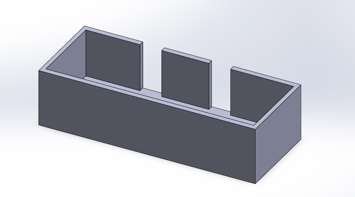
I was out of town for Veteran's Day weekend, so I made sure my goal was attainable in the short time I had in lab and went in with a planned workflow. I began by designing a simple housing for my capacitive sensor, as I didn't want to have to hold everything together with my hands. This took approximately 2 minutes to design and approximately an hour to print.

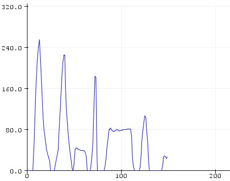
Next, I had to write the code to turn my arbitrarily high output into an analog signal (between 0 and 255) to control the brightness of the LEDs. This was essentially brute-forced; I found the (approximately) absolute maximum and minimum values of my raw output signal by letting the sensor sit both pressed and unpressed for a decent amount of time. Then, because Arduino's map() function only takes integer arguments, I divided the output by a sufficiently large number that the result of the division could be easily stored in an integer. This allowed me to easily write a map() function into my loop, yielding sensor outputs between 0 and 255 (with some if statements to make sure it didn't exceed 255 or go below 0). This graph, much prettier than last week's, is an example of me variably pressing my sensor for a few seconds:

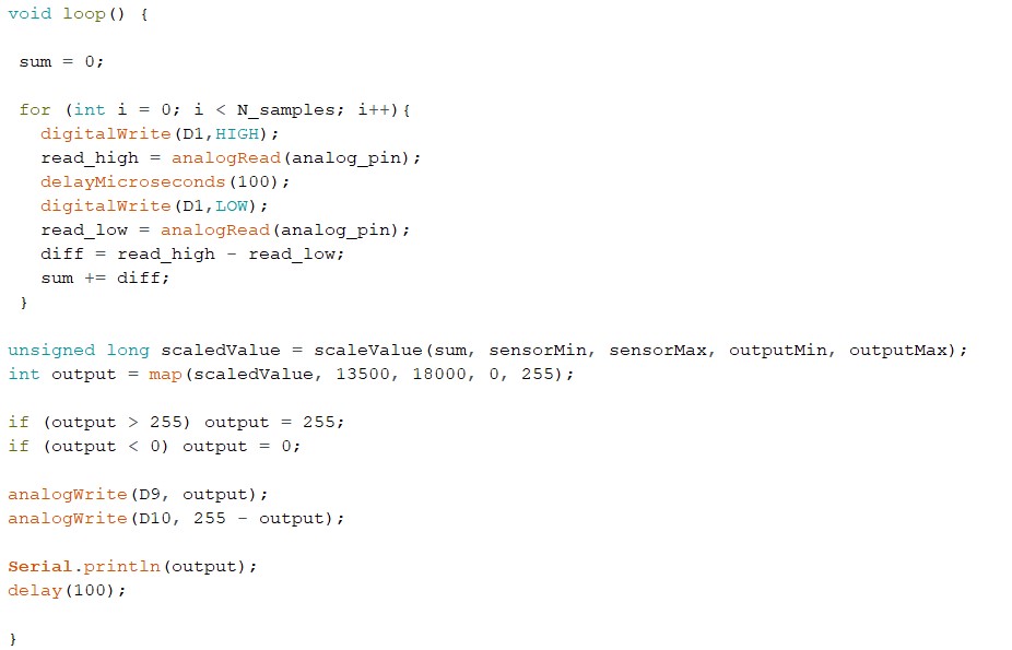
I wanted the LEDs to be opposite; that is, one would be at full brightness when the force sensor output 0 and the other would be at full brightness when the force sensor output 255. Note that the digital pins of the XIAO RP2040 are PWM capable so I can simulate an analog write to pins 9 and 10, which are connected to the LEDs. This was quite simple to implement and my final loop ended up looking like this, including a 100ms delay (the sampling rate is very subject to change, this pick was somewhat arbitrary as I just wanted to make sure the loop had time to run) and a Serial output so I could check my values as I coded:

And thus, my sensor was characterized and my lights were working! I did observe some strange behavior depending on where my sensor was placed. For example, trying it on the tables in the EECS labs gave me significantly different outputs than trying it on the EDS' wooden table. Interestingly enough, the range of outputs when the force sensor was on the EECS tables, with many outlets and wires and whatnot, almost exactly matched the range of outputs when the sensor was placed on top of my laptop keyboard. I'm curious if that's a coincidence or not, but I digress. Please enjoy this footage of my force sensor controlling the LEDs' brightness, featuring the audio of my roommates watching The Walking Dead in the background: