Week 8 Assignment: Make Something Big
For a while, I've known that I wanted this week's project to be something I could actually use. As it turns out, there are no real tables in my room other than desks, and I figured my roommates and I could use one.
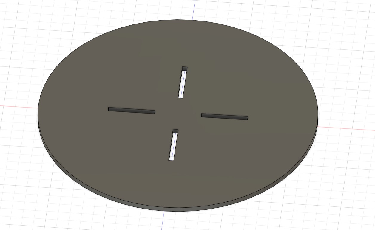
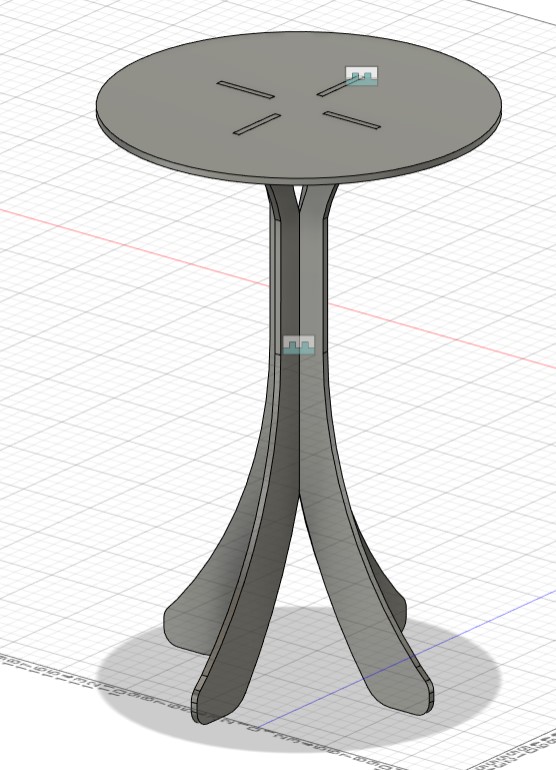
Given the soft space constraints for this project (Anthony recommended that we only require one milling job on 4' by 4' OSB), an image of the kind of table I wanted to make immediately jumped to mind. A nice round end table to put next to our couch sounded lovely, and quite possible to fit on such a board. I hopped into Fusion360 (I usually prefer Solidworks, but I didn't feel like transfering a Solidworks assembly to Fusion and I could benefit from getting used to the latter anyway) and began sketching up my idea of a tabletop. Knowing that the OSB was nominally 7/16" thick, I sketched a circle with 4 slots in a "+" shape into which the legs would be inserted:
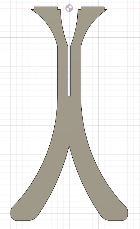
I then got to work on the legs. I knew that making four separate legs would be detrimental to the structural integrity of my table, so I envisioned two sets of two opposite legs, which would press-fit into each other and then attach to the table. With this specific project, I think there are many different ways to design legs that work, so I ended up going with my gut. Of course, I made sure I recorded dimensions as I went to ensure that I could fit each component onto the single OSB board and that I could make a second pair of legs that fit with the first. I also made sure I got the dimensions exactly right for the tabs that fit into the slots on the tabletop - that's actually where I began this sketch. I just didn't have overly strict design specifications otherwise. I ended up with this:
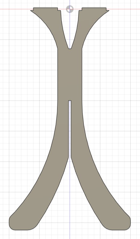
I like the look of curved legs on a round table, and I was quite happy with this design! Because I designed the first pair of legs fairly robustly, making the second pair was quite simple. It took a couple of operations, but imagine just "mirroring" the slot about its bottom edge:
I quickly put everything into an assembly to make sure all of the components lined up:
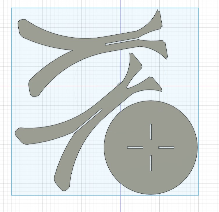
I was feeling really good about my design, so it was time to arrange and toolpath! My tabletop was 24" in diameter, so as to take up about one-quarter of the OSB, and I ensured my legs weren't *too* big as I designed them. I was thus left with this arrangement of parts, after a little bit of adjustment to make sure nothing was too close:
Toolpathing was quite straightforward, though I got a fair bit of help from Anthony as I was less experienced with 2D toolpaths. I made sure to cut most of the material with the 3/8" endmill and finish everything off with the 1/4" endmill, setting up the router to leave tabs to keep my components in place and dogboning inside corners with a Fusion add-in on Anthony's computer (I attempted to use one of the add-ins linked in the Gitlab, but they unfortunately didn't work for me, which I heard was not an uncommon problem). As I did last week, I set up the router, the only differences being that 1. this week I had to zero the X and Y axes as well because they weren't hard-coded by the lab staff like they were for the wax blocks and 2. I had to nail the OSB sheet down with composite nails, which wouldn't harm the endmill like normal metal nails would. After a very short (~10-minute!) job, I had this:
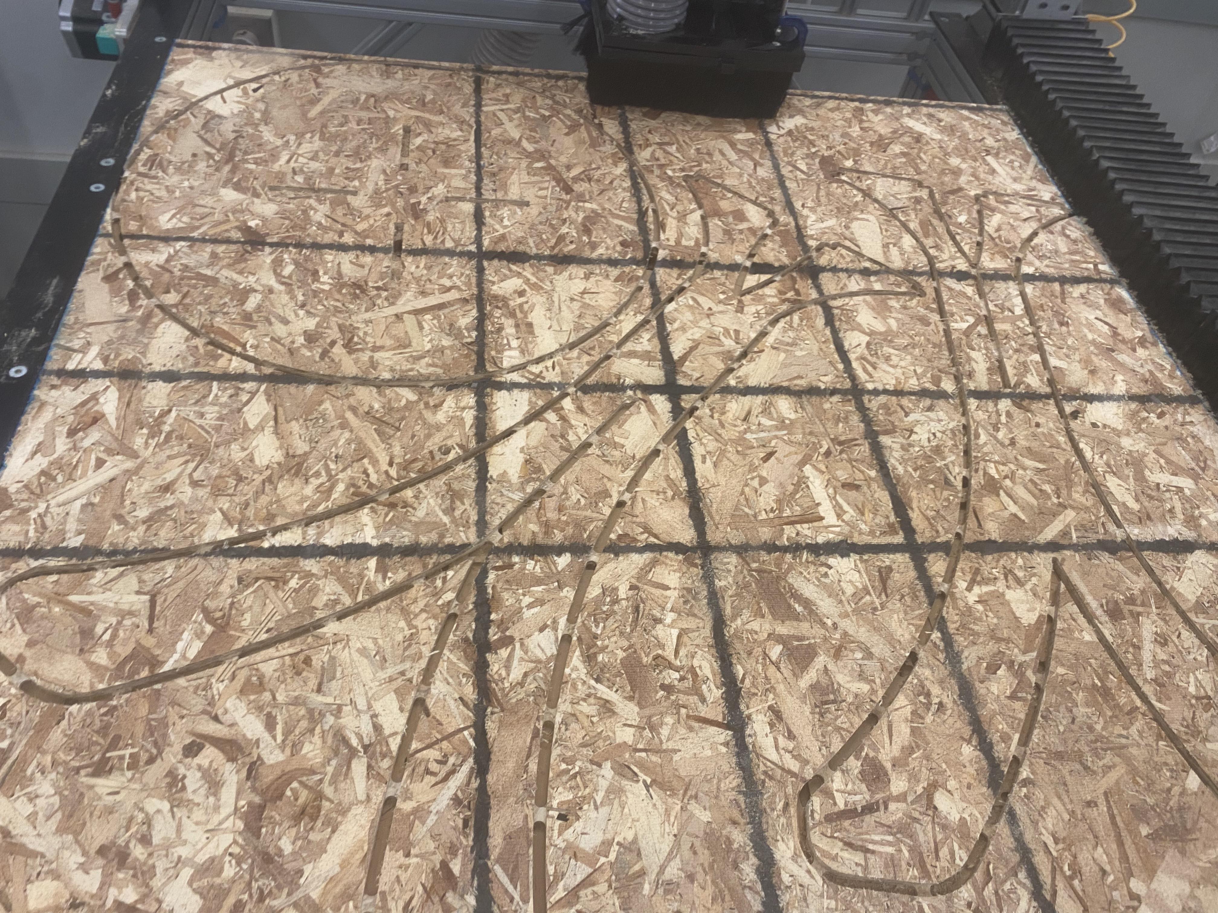
I still had to finish cutting the tabs to fully free my components. Essentially, the tabs are left by the router to ensure that the components don't move and ruin the job while it is in progress (hover over the image to zoom in; it might help to see the tabs better). With this, I simply used a high-frequency reciprocating saw that cut through the OSB like butter, then gently hammered the side of the components to get rid of the nail holdings (the composite nails are strong in compression but very weak to shear force, making them ideal for holding things down temporarily to later be easily removed).
After I had cleared all of the scrap off of the router, I had to file and sand my parts so they fit together optimally. I left the width of the slots in my CAD as exactly 7/16", as I figured I could always remove material but didn't want to risk the slots being too wide. This part was pretty simple: use an oscillating sander to smooth out the edges, then file away any parts of the joinery that didn't fit. About a half hour of this process later, my table was assembled (but not quite fastened), and I was very pleased that it looked just like my assembly:
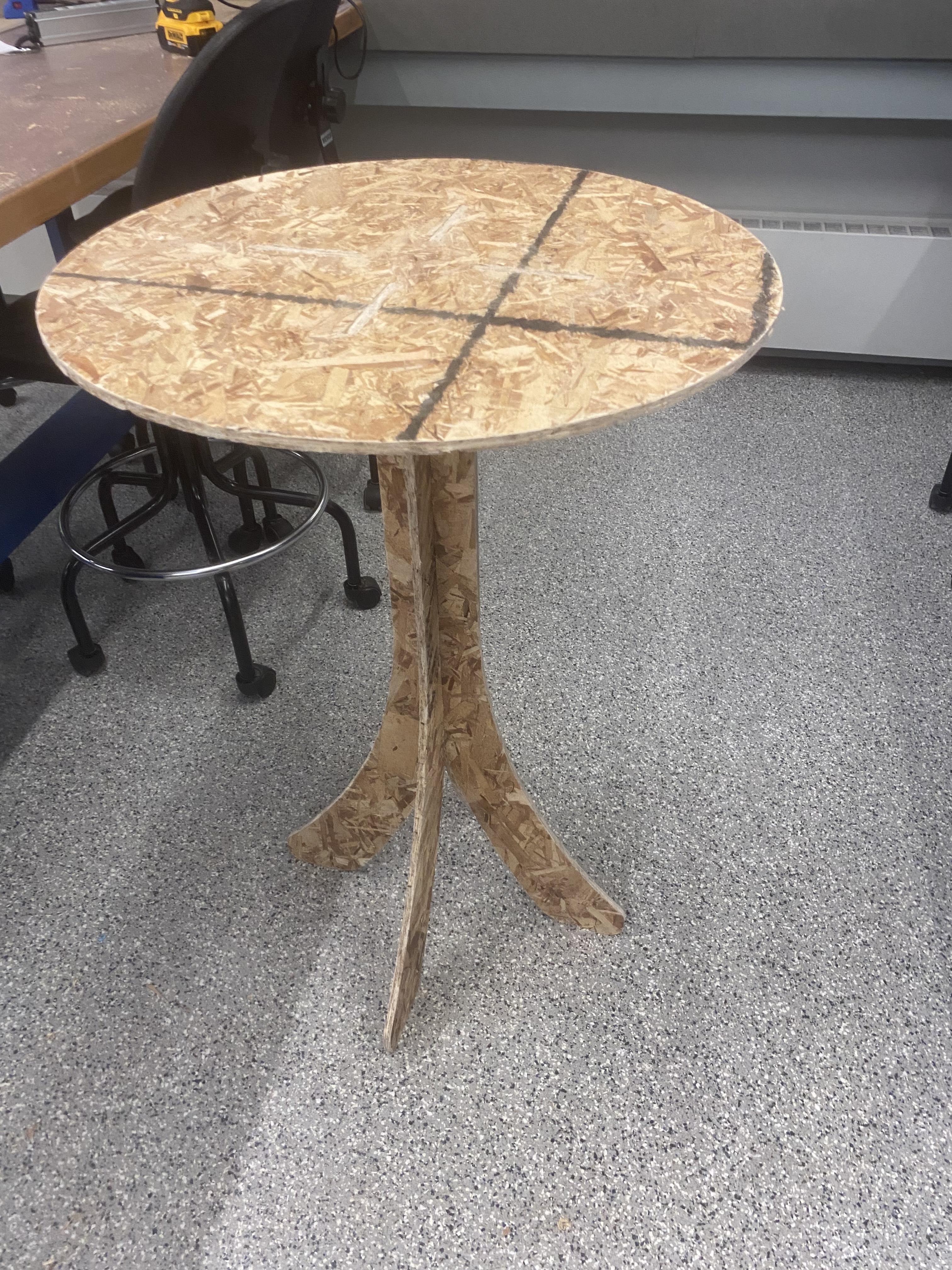
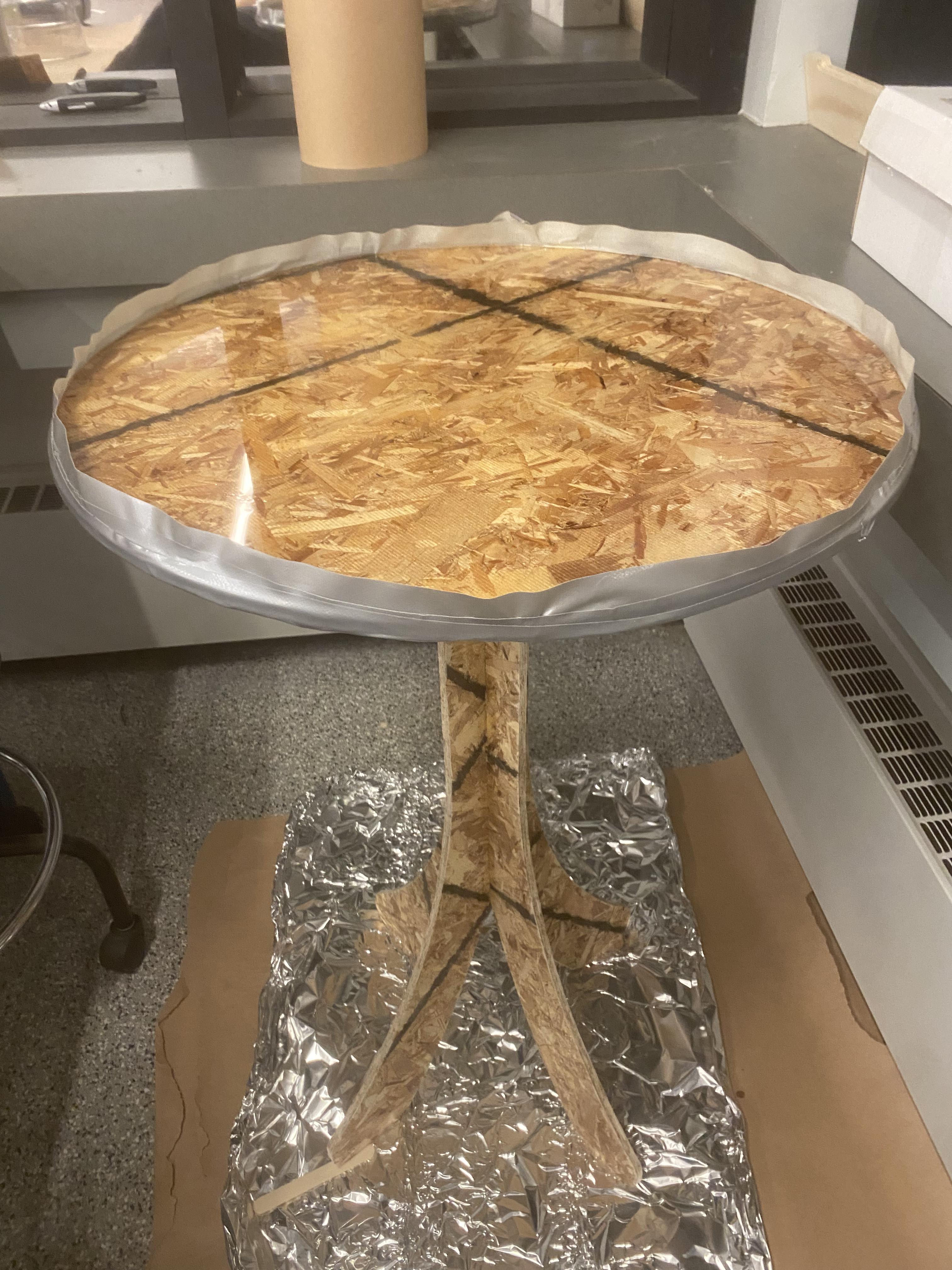
I only had two things left to do: use wood glue to fix everything together and create some kind of top surface so that the tabletop wouldn't just be OSB. The wood glue part was easy: I glued up all of the points of joinery and gave it about 45 minutes to rest before moving it again, knowing that I couldn't put it under too much stress until I left it to dry overnight. For the top surface, my first idea was to vinyl cut a sticky "tablecloth" to attach, but I asked Alec about it and he suggested I use epoxy, an idea I really liked. I had never used epoxy, but a clear resin top would allow the OSB to be seen, and I kind of liked the rugged, "I made this myself" effect of that. So, Anthony helped me mix and pour the epoxy, a process that was more straightforward than I thought. I first thoroughly stirred the epoxy parts A and B together in a 2:1 ratio, then put the mix in a couple of cycles in a vacuum chamber to remove air bubbles. After heavily taping the sides of my table to ensure the epoxy only covered the top and didn't drip down, I gave it a pour and had a nice shiny top that would soon be set: