
HTMAA Week 11
Assignment Description:
Design, build, and connect wired or wireless node(s) with network or bus addresses and a local interface.
Networking Week
This week will have updates as I further develop the networking solutions for my final project.
This week was a frustrating one as I faced a few unanticipated hiccups that really slowed things down.
The Plan
In week 10 I outlined my creation of the board that will control the pumps and input devices for my final project, an automated watering and feeding system for my hydroponic gardens. This week I want to create an additional board that will handle the UX side of my project, as I am just about out of free pins on the other. I want the following features:
- A camera to take a timelapse of plant growth (and optionally a live feed)
- A web server to interact with the system, check data, and test components
- Physical buttons for UX, testing, and status updates
- OLED Screen to show status messages
Given these requirements, the Seeed Studio Xiao ESP32S3 Sense is a great fit given the built-in Wi-Fi, camera module, and SD Card slot. Moreover, I will connect this board to the Pico controller board over serial inside the project housing, so that controls from the web portal can be sent to the pumps.
First, I started by testing the ESP32. As I have been utilizing MicroPython for all of my embedded programming up to this point, I wiped the stock firmware and installed MicroPython by following this tutorial. I had to do some google-fu to tune it to work on Mac, and I used the following commands:
					ls /dev/tty* | grep usb  # to find usb serial port

					esptool.py --port /dev/tty.usbmodem101 erase_flash

					esptool.py --port /dev/tty.usbmodem101 --baud 460800 --before default_reset --after hard_reset --chip esp32s3  write_flash
					--flash_mode dio --flash_size detect --flash_freq 80m 0x0 firmware.bin
Once I had micropython installed, I tested the SD card functionality, which is where I ran into my first major hurdle. The code for doing so is rather simple:
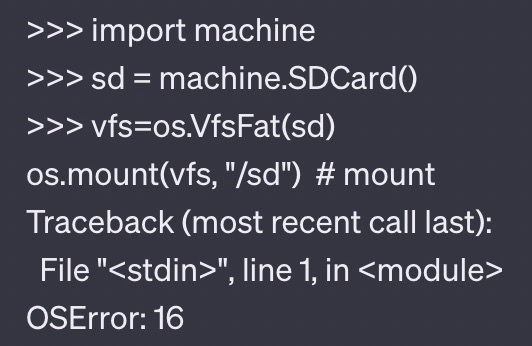
At first, I thought the issue was that I was using a 64GB MicroSD card, and the documentation states it supports a max of 32GB, so I ordered a smaller card. However, this did not resolve the issue. After some GitHub Issue Sleuthing, it appeared this is a common problem, and none of the solutions worked for me. Since I required SD Card functionality to store the photos for a timelapse, I aborted on MicroPython and switched to arduino.
I successfully tested the following code snippets:
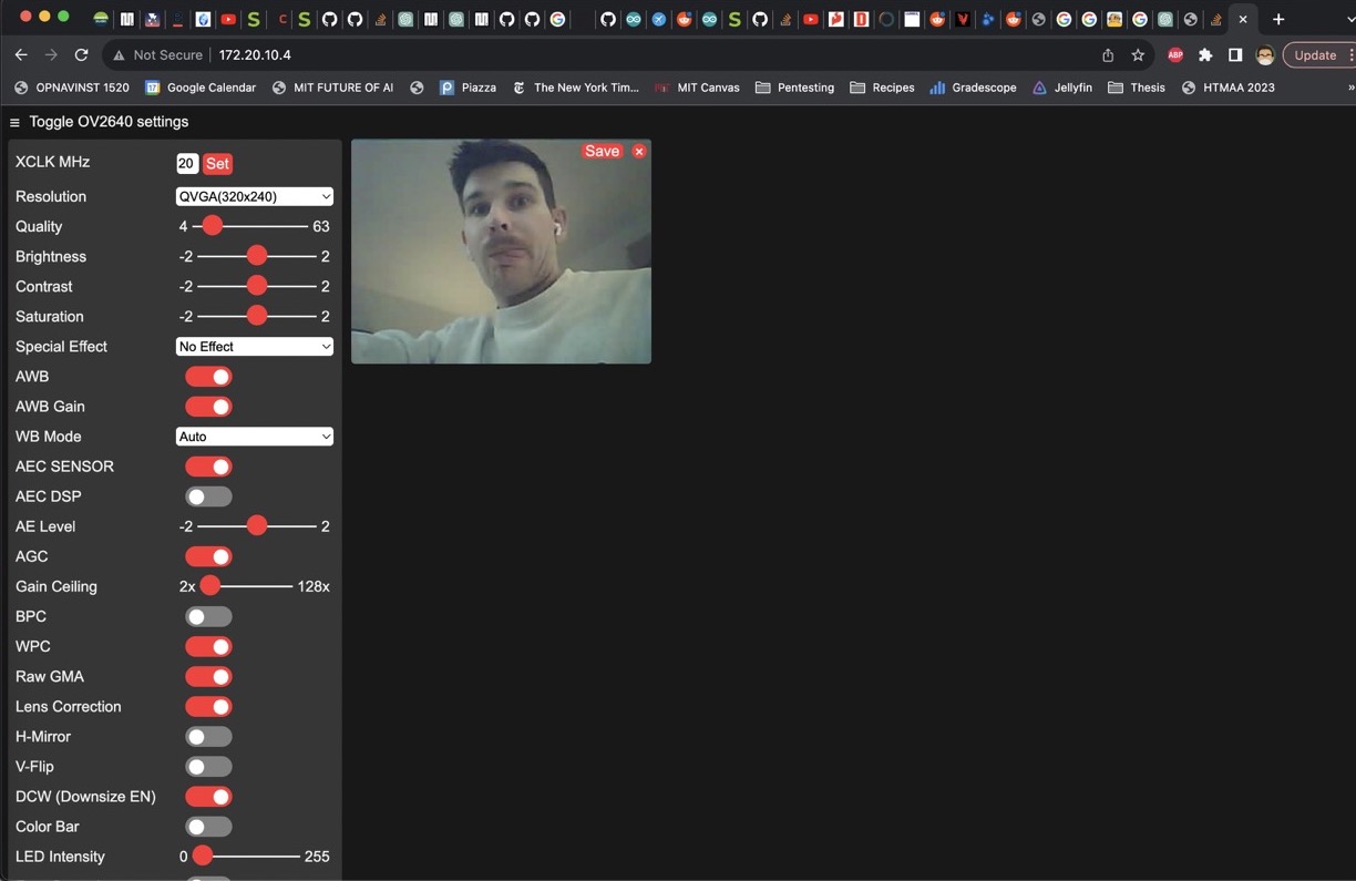
- Built-In Camera Web Server Example
- Takes a Photo Every Minute and Writes to SD Card
- Tests SD Card Read/Write
The Camera Web Server example, streaming video from the ESP32 to my laptop:
Board Design
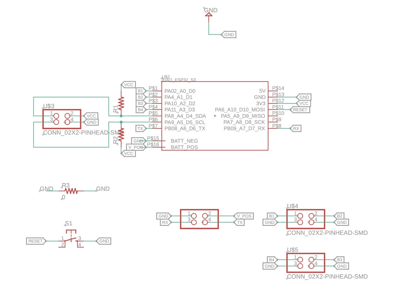
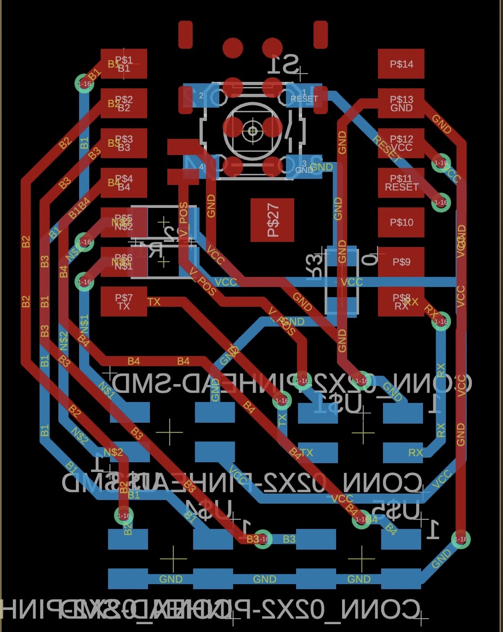
Given my listed requirements, I needed to expose most of the pins on the Xiao. Moreover, I wanted to directly power the board (vs. via the USB-C port) with the pads on the underside of the board. My main (Pico) board has a voltage regulator with a 5V line, so I figured I'd use that same line to power the ESP32. Although the footprint in the fab library had these pads exposed, the schematic did not. Therefore, I had a fun time figuring out how to edit the library and the schematic to expose the power pads in the schematic view. Here is my completed schematic:
Since the camera needs to be up against the wall of the body, I decided to make a double-sided board.
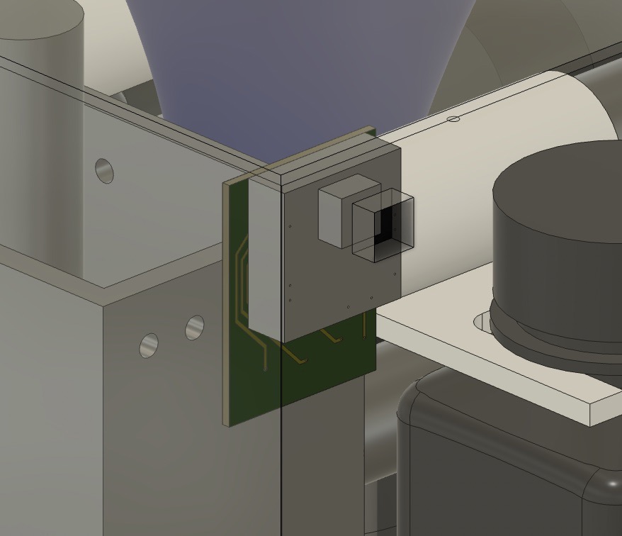
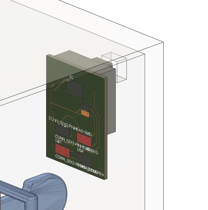
This enables a pretty small footprint:
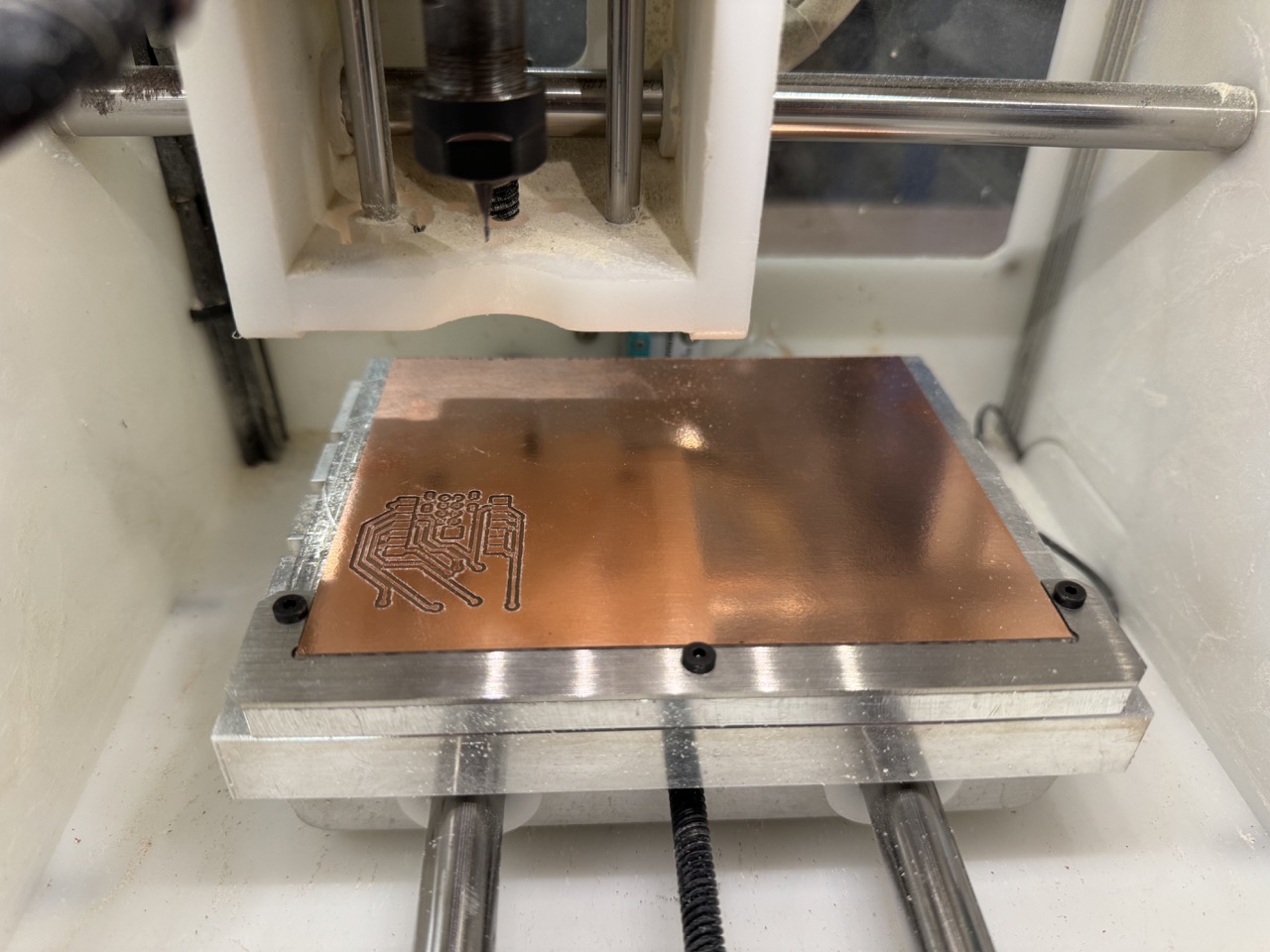
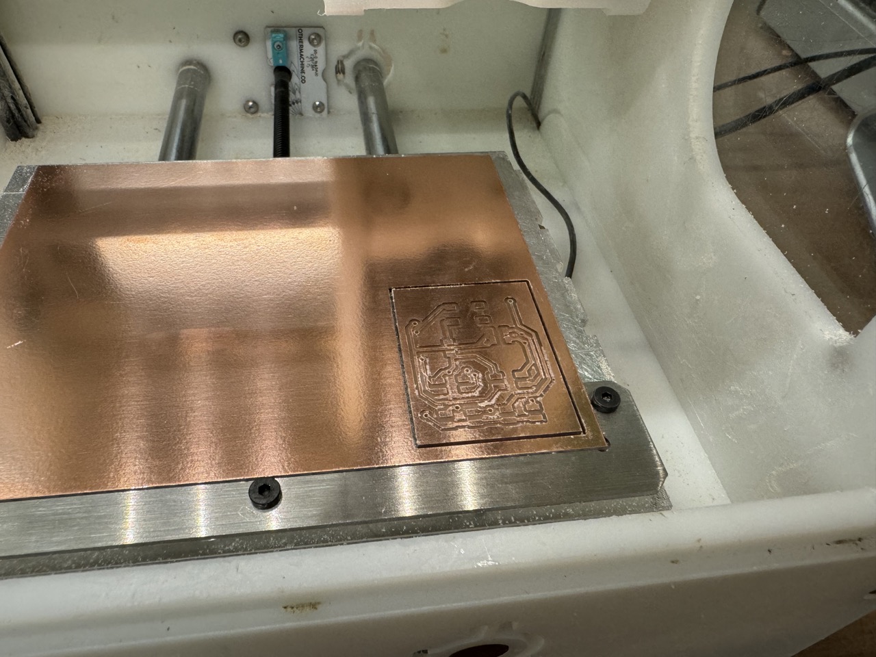
Fabrication
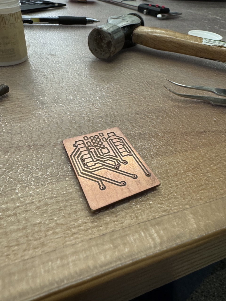
This was my first time making a double-sided PCB, so Anthony helped me with installing the alignment bracket and locating it on the othermill.
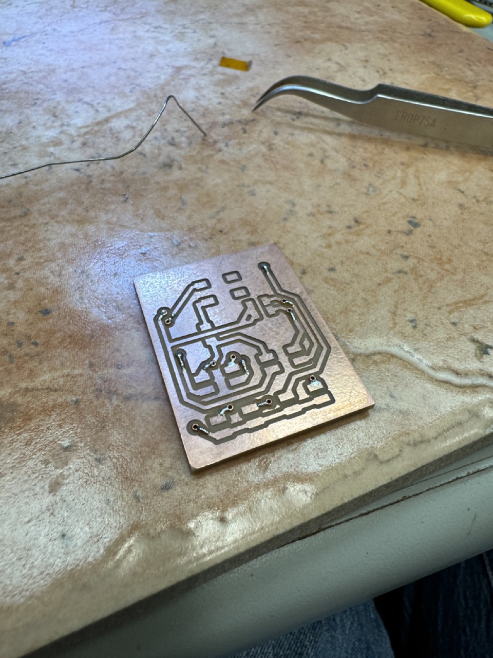
I then installed rivets to allow conductivity through the vias:
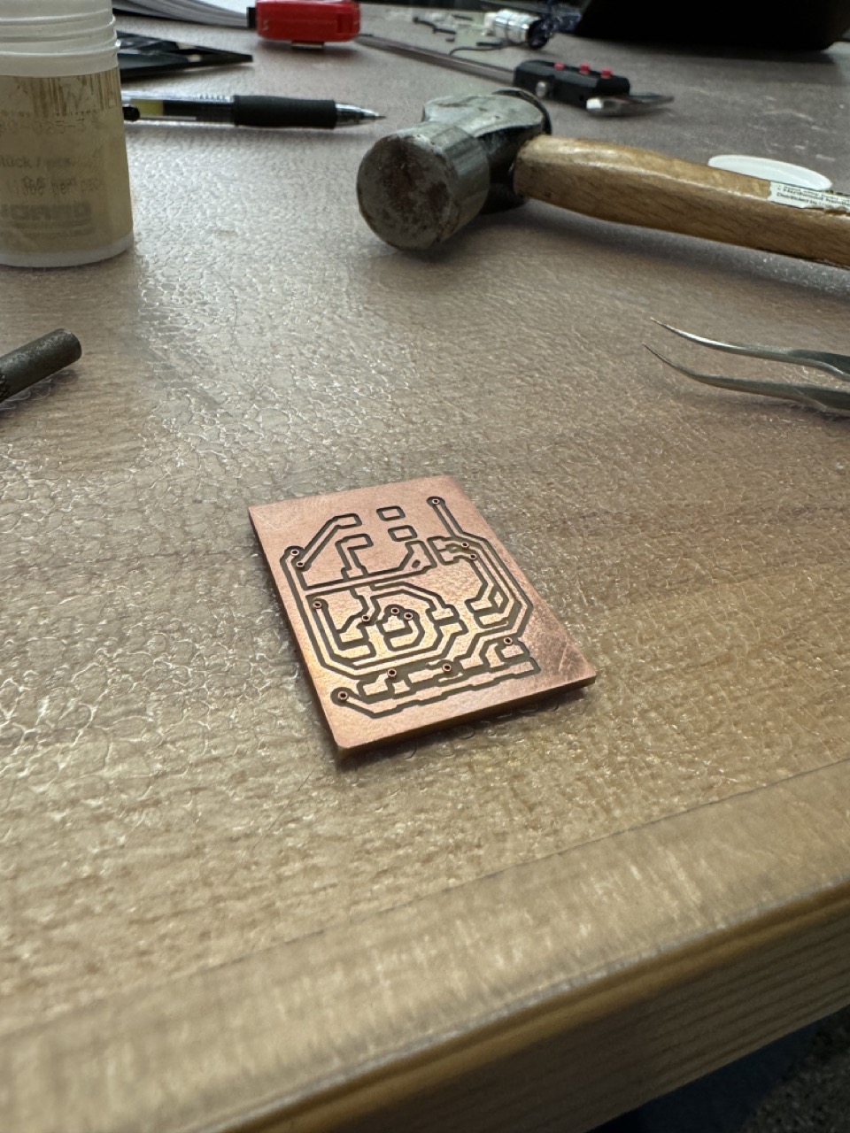
Then soldered them to ensure connection:
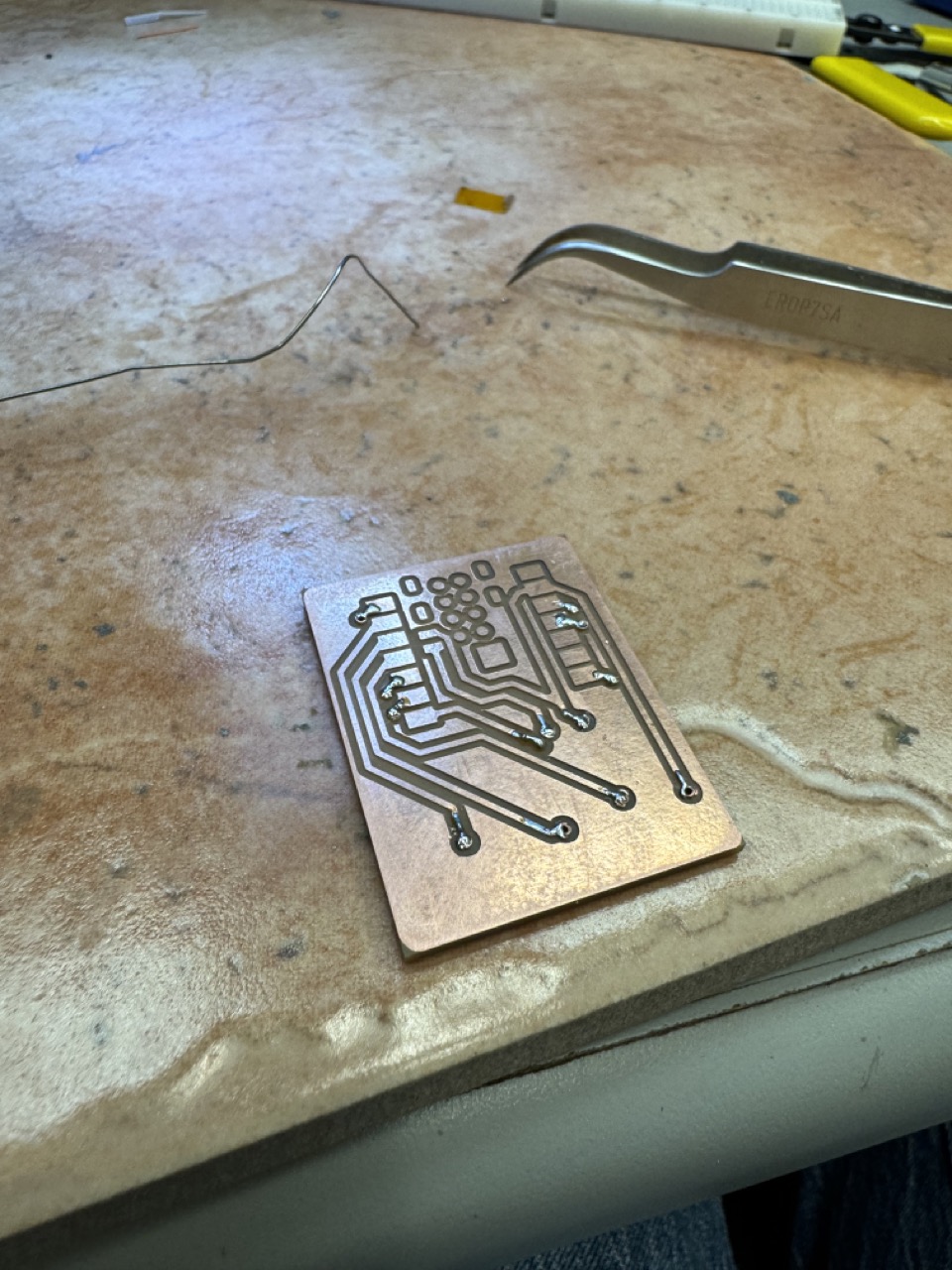
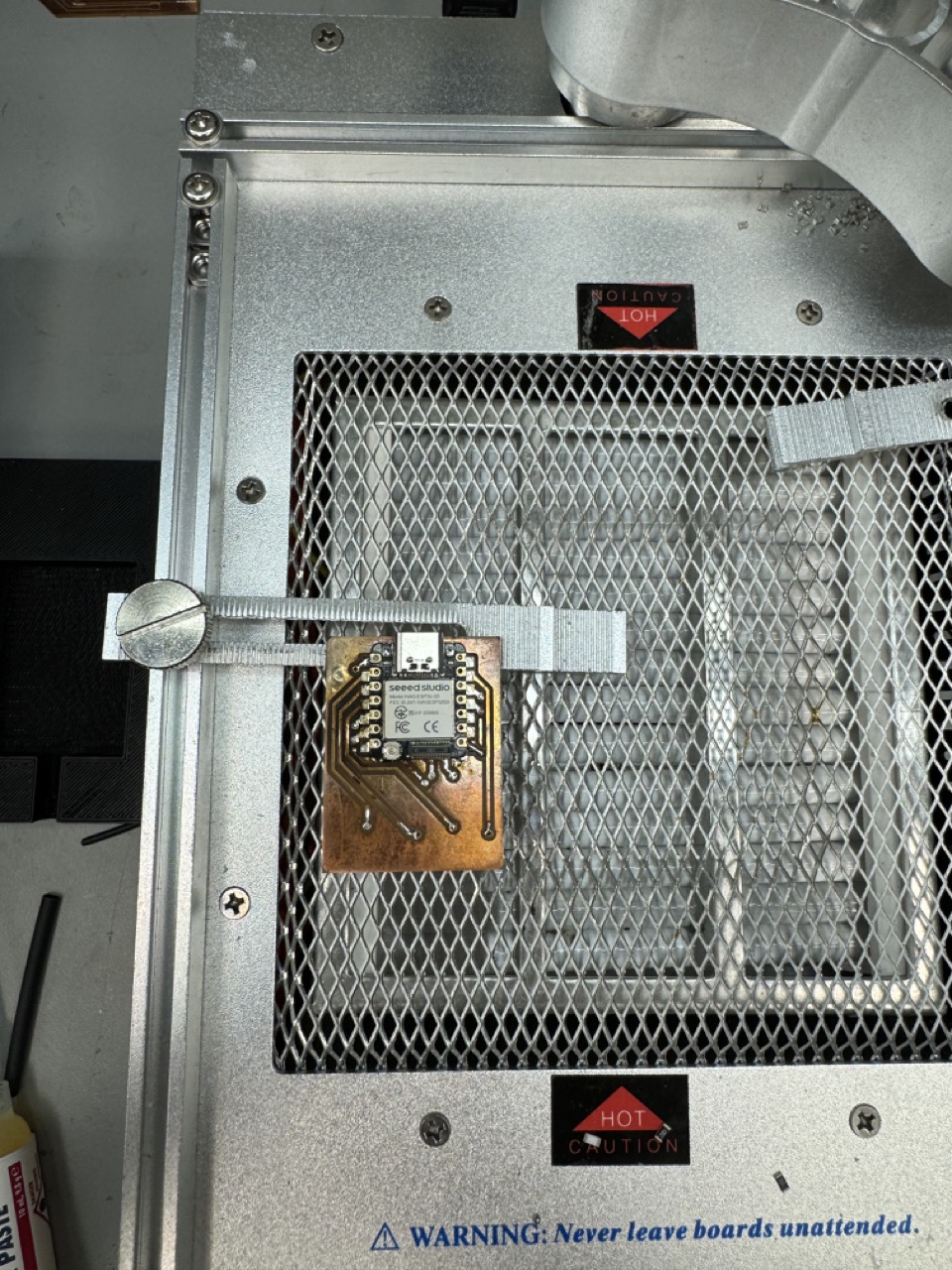
In order to connect to the pads underneath the board, I used solder paste and the reflow station. The positive and negative pads kept shorting, so this took several attempts, and eventually I just taped over the negative pad as it is connected to ground.
Serial
I had a lot of struggles with getting the serial to work between the two boards. Here is the code that finally got the two working in sync:
MicroPython:
					uart = UART(0, 9600)
		uart.init(bits=8, parity=None, stop=1)
Arduino:
					HardwareSerial MySerial0(0);
					MySerial0.begin(9600, SERIAL_8N1, -1, -1);
    				MySerial0.print("MySerial0");