
HTMAA Week 4
Assignment Description:
Design and 3D print an object that could not be made subtractively
3D scan an object
Print Final Product
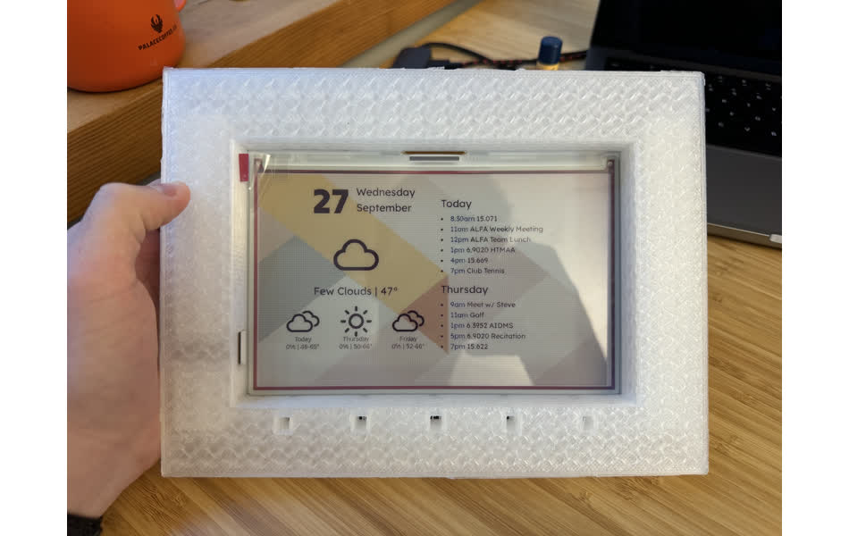
This week I expanded on my project from last week by creating a frame for my e-ink dashboard to sit in. The frame contains internal features (although they are difficult to see) that make it an object that would be impossible to create subtractively from a single piece of material.
Modeling in Fusion 360
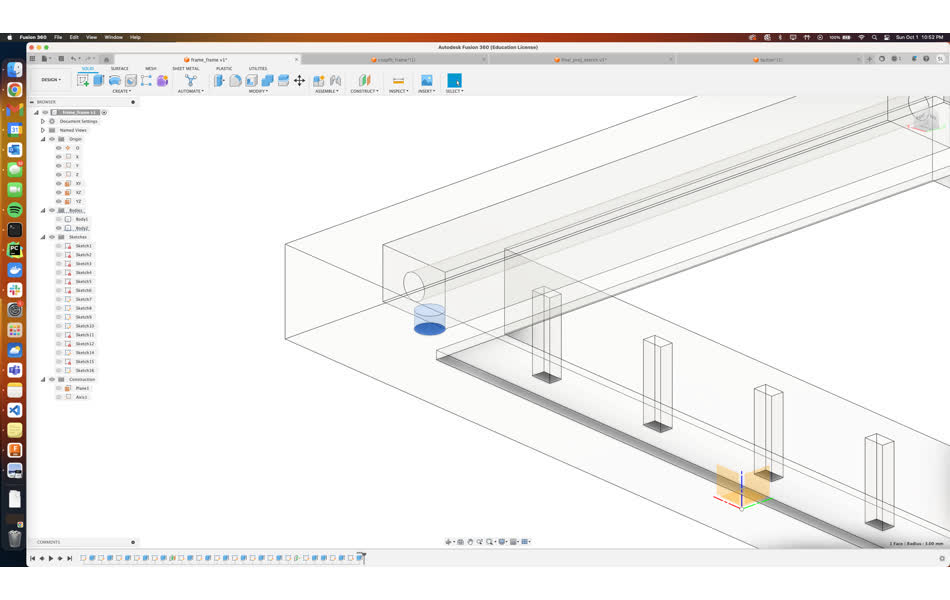
Before designing the frame itself, I first started by modeling the inky display itself so I could better vizualize how the two would interact. This is actually a task I performed in week 1 when I was struggling to remember how to use CAD (the last time was 7 years ago in high school). Because I have grown more familiar with fusion 360 over the last few weeks, especially after week 2, I decided to just start fresh.
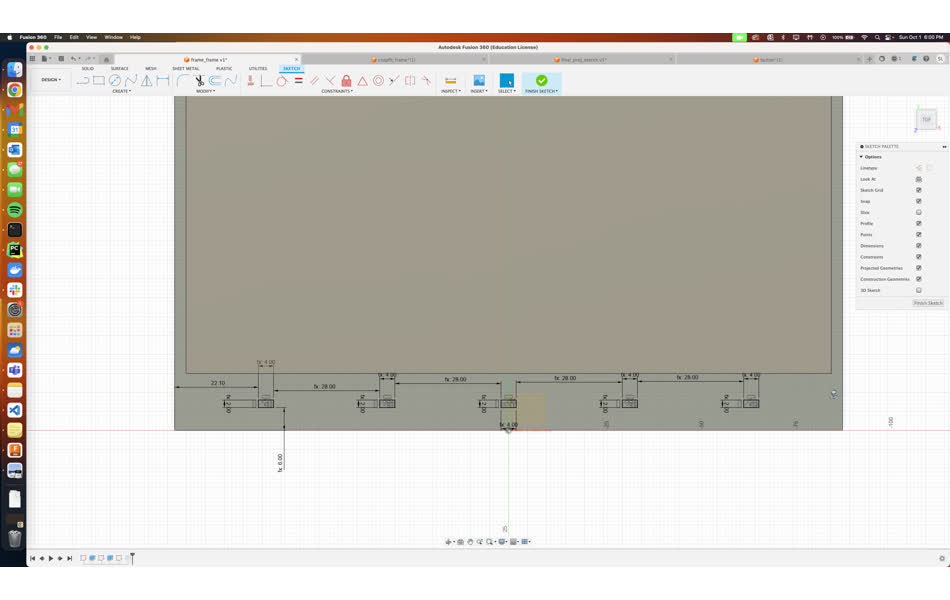
This reinforced the importance of parametric design principles. At home the only measurement tool I had was a level with 2mm markings, which is obviously not ideal when printing something that is supposed to interact with and hold another object. But, I created parameters for all of the relevant measurements with a course grained measurement, which was good enough for creating the design. Then, when I went into the lab, I used the calipers to extract fine measurements, updated the parameters, and bam! Everything adjusted.
The design started with a basic picture frame style outline of uniform thickness. In addition, I needed to account for:
- The front buttons
- The reset button on the back
- The battery pack
- The Pico's micro USB port on the side
- The thickness of the filament itself (0.6mm) for fit measurements
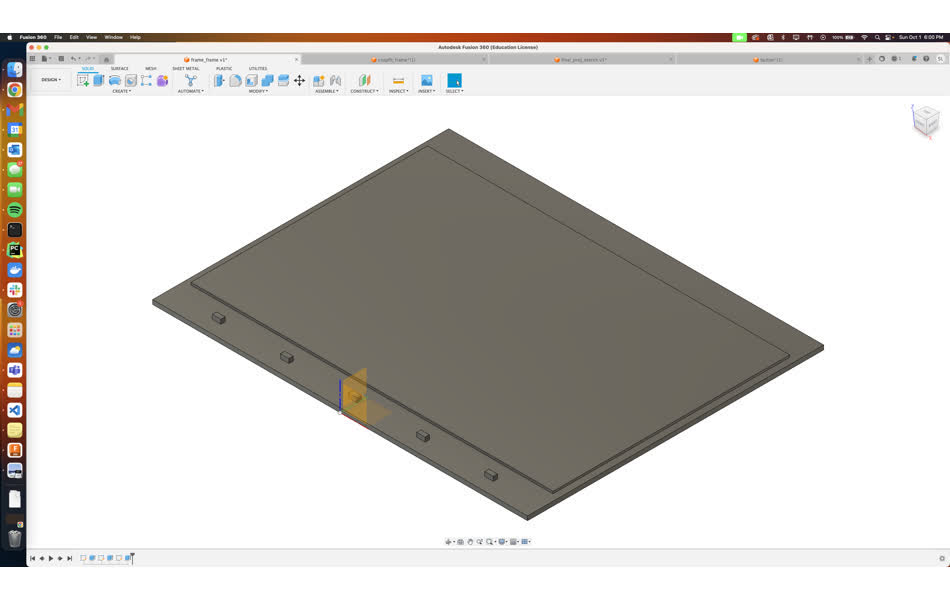
I planned on utilizing the transparent PLA filament in EDS on the Prusa, so I applied the "frosted glass" texture so that I could see any internal features.
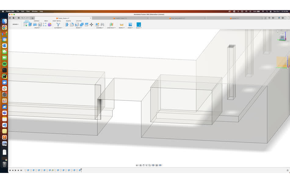
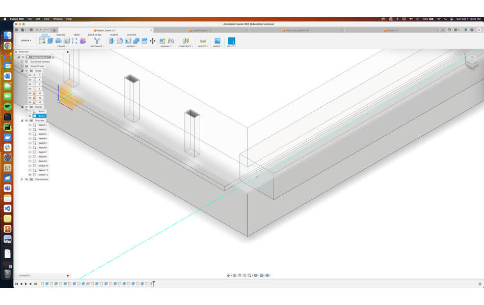
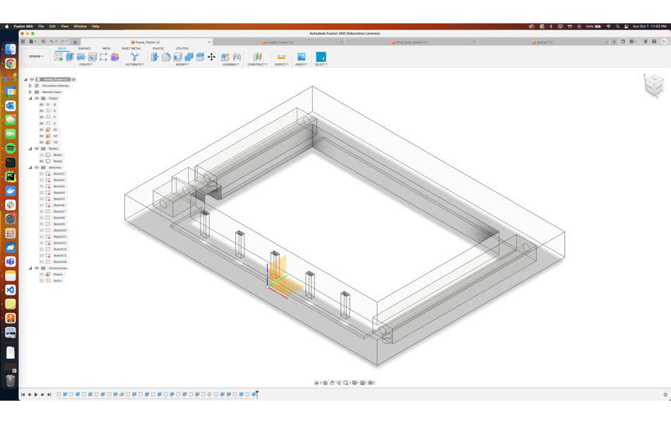
Because I planned to use the transparent filament, I created an internal cavity with a pillar, hoping that it would be visible from the outside of the frame. I created an access hole in the back for adding an LED to light the frame from the inside. Adding this LED is a task for the future and plan to link it to updates on the display.
Printing
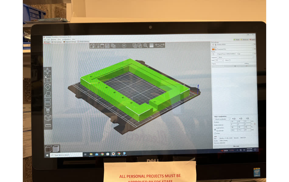
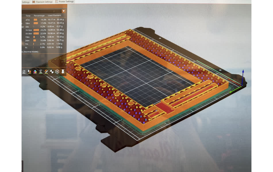
After completing the design in Fusion 360, I exported it to .stl, and loaded it into the Prusa slicer. I flipped the part 180 degrees so the Micro USB cutout and display inlet were not printed hanging. Moreover, because the frame is a pretty large object without fine details, I printed it on the Prusa slicer "fast" preset. Finally, to reduce print time and since the part doesn't really need to be strong, I set the infill to 15%. The slicer window halfway through the part shows the internal columns and infill structure.
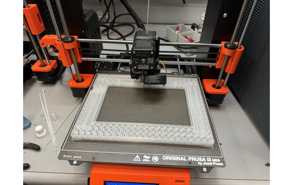
The print took 5.5 hours and went off without a hitch. The Internal columns aren't quite visible given all of the refraction going on with the walls of the cavity itself, but I hope the addition of LEDs will help. Future improvements also include: 3D printed buttons, status LED cutouts, a better mount, and an improved Micro USB slit.
3D Scan
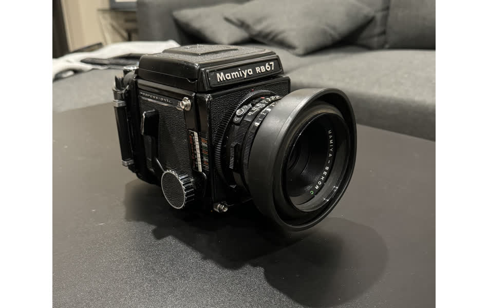
I decided to create a 3D scan of my Mamiya RB67, a medium format film camera. I ran through the demo of the scanner in EDS with Anthony, but decided to try out an iPhone app scanner since I've never used its LiDAR sensor. I downloaded Polycam and used its LiDAR mode first:
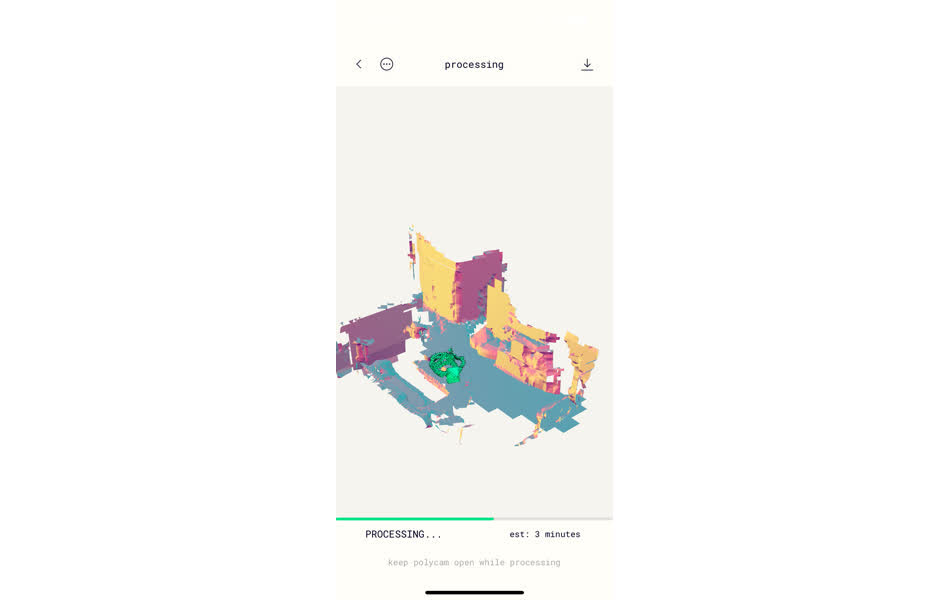
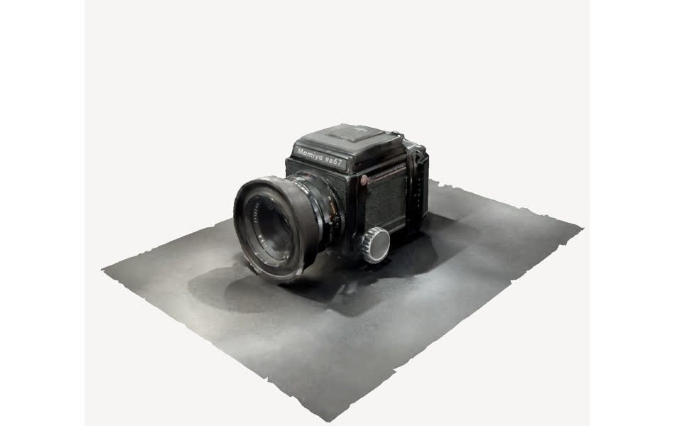
The green blobs on the left show the path I moved the phone to conduct the scan. Moreover, the LiDAR sensor was also able to detect quite a lot of the geometry of my apartment as well. The processing was completed on-device.
Polycam mentions that LiDAR scans are best for large geometry such as buildings and rooms, while image scans (photgrammetry) were better for small objects. I conducted an image scan with 150 images, which were sent out to Polycam servers to compute the 3D model:
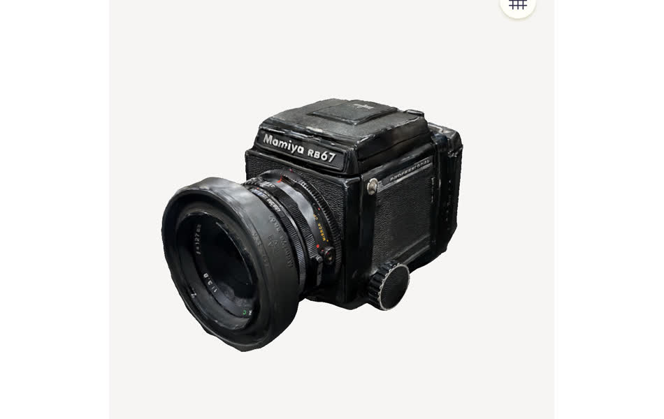
Overall, I was impressed with the generated models. Exporting to .stl for printing requires a subscription, so sadly I was unable to print a mini version of the camera.