this week the assignment was to work with output devices (led screens, motors, speakers, you name it). since i'm pretty sure that my final
project will take big advantage of motors, and i find them fascinating anyway, i knew this would be a good week to dig into that. also it didn't
hurt that i had advanced warning that my site will be critiqued in front of class this week o.o
i started off my going to jake's office hours on thursday, and a few of us learned the ins and outs of driving motors with and without using drivers.
mostly the takeaway is that there are a lot of things to consider, and it is much more complex than it looks (motors are everywhere, and they just... spin?).
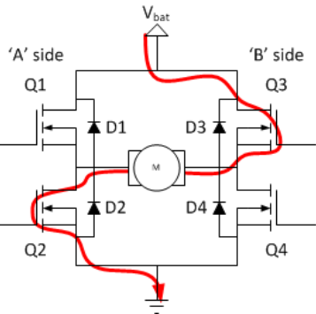
namely, the component that allows stepper motors to drive in both directions is an h-bridge, an h structure made up of four transistors
usually mosfets (metal-oxide-semiconductor field-effect transistors) that work on voltage instead of current like other transistors do. this means
that when the gate voltage is low the switch opens, and when the gate voltage is high the mosfet is like a very small resistor. this means
that you can put a lot of current through a mosfet and as long as resistance is low it won't get too hot.
jake walked us through what it takes to make your own motor driver, including using these toshiba h-bridges with an rc filter in order to to give the flexibility to adjust current to the spinning of the coil so that it aligns and doesn't skip basically. the concept overall is that you want to control the polarity of the coils so that the polarity of the magnet in the center is spinning to realign polarities with the coil. in order to do this effectively and predictably though, it involves some complicated coding, i.e. sending the microcontroller an array of sinusoidal values so that it spins, amongst other things.

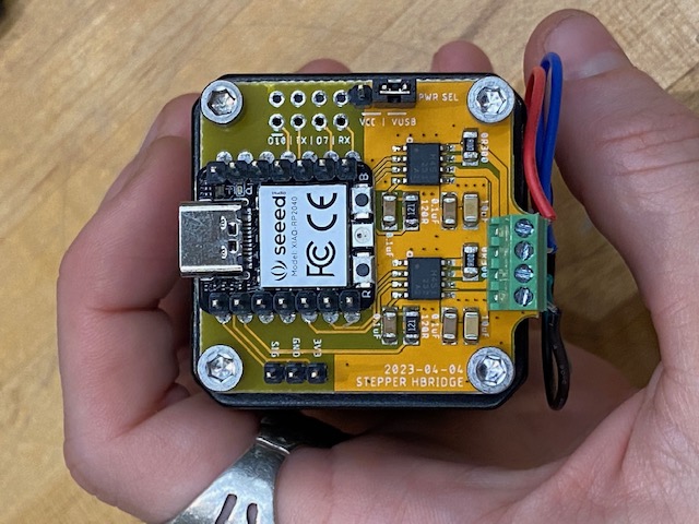
after we walked through just how tricky it can be, and jake showed us the couple beautiful motor driver designs he made that fit perfectly on the backsides of the stepper motors, he told us that there is a pretty simple and cheap alternative to designing it yourself.
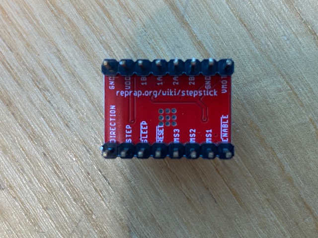
and that is, using a step stick. the idea is that the step stick has the rc filters, the h-bridge, and most of the code already encoded, so all you need to provide to run a stepper motor using a step stick is power, ground, a value for direction, and a value for step to determine how the motor moves.
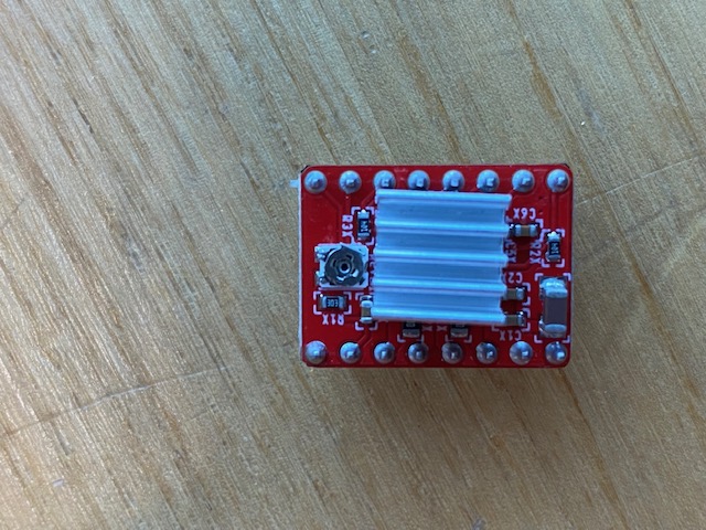
jake also recommended using a usb pd decoy so that you could run it off a fast charger (instead of batteries or desktop power, for portability and pcb-ing). he suggested that even if we want to make our own motor drivers (which i do), that we start there.
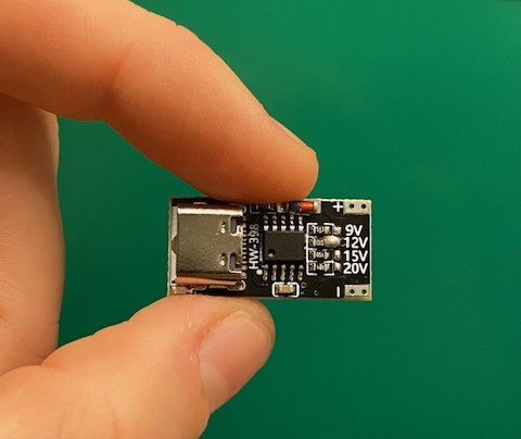
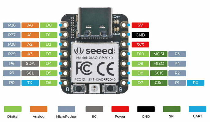
i ordered pd decoys from amazon and the step sticks we had at harvard. theoretically, you should be able to short the fuse on the pd decoys to select which voltage is output, but despite by soldering a couple and testing them, i've only managed to get 9v out still. unlike the other electronics weeks, i started this week by wiring up with jumper wires, just to make sure i understood everything and didn't have to commit when i wasn't sure if it would work, and decided to start with a xiao rp2040 for a microcontroller.
i found this super helpful guide that had a great initial guide for wiring up the step stick and they drew up a nice diagram so i don't have to re-draw it!
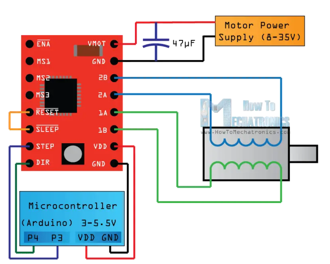
the most important things to note here
are that the trimpot should be dialed all the way down (to the left), and that the sleep and reset pins can be shorted together since the reset pin is floating, it brings
it high so that we can work with it.
the trick that we had discussed with jake is that getting the amperage tuned is important and a bit tricky, and the trimpot on the step stick allows
us to tune it manually (spinning it slowly until the motor engages, you can hear it go from whirring and struggling to spinning).
i wanted to add two buttons so that you could send the motor left and right so i re-wired it so that it looked like this.
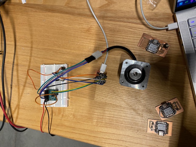
after changing the code to have the two data pins be pull down input resistors to flag when the button was pressed, the motor now runs counterclockwise with the left button and clockwise with the right button!
so i designed a sweet looking pcb with cut outs to match the stepper motor screw holes so that it could be mounted on the back with some spacers. [[[ many issues to come ]]]
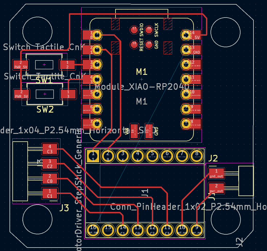
i milled the initial pcb and then went to put components on it. there were two tricky components that i knew would be tough but i didn't know that it would be impossible. i originally tried to mimic an example neil showed to solder components with throughholes. i started by removing the pins from the step stick (ok now people who know electronics are laughing at me, but bear with me... )
so then obviously the issue was trying to get the irregular pins back through the step stick holes which were full of solder. obviously you have to heat all the pins at once, and now they're not aligned because the plastic got warped, and they're only very carefully and fragily attached to the traces so i was too nervous to use a heat gun and it gets really tricky (i would say impossible) to attach this way.
the other way that quentin had suggested was to attach it from the bottom. i wasn't initially
eager to do this because minimally, i preferred the look on the top but importantly, i also wanted to be able to mount it on the back of the motor,
and it wouldn't be possible (because of the screws, discussed later). with leo's encouragement though, i went for the redesign.
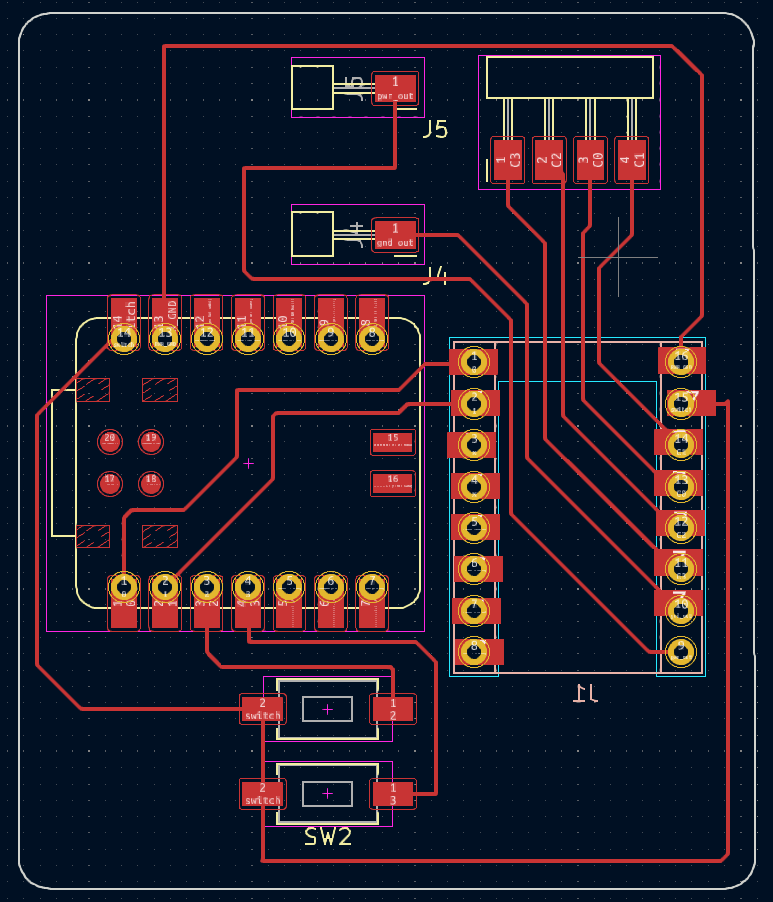
so then there were many new redesigns that had to happen. i had to redo the traces on the pcb for an inverted step stick, which
was fairly fast.
the most unfortunate thing was that there weren't longer screws that would fit the motor backing, so i also had to do a redesign of
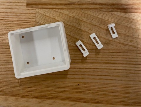
how the pcb was going to mount to the board. i quickly designed something in fusion360 that i could 3d print and mount in between
the board and the motor backing.
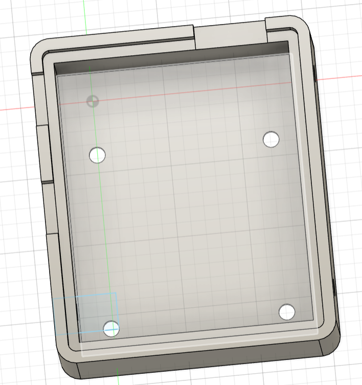
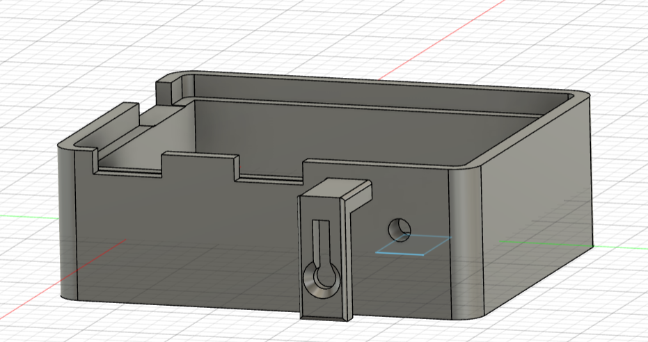
luckily it was very quick to design and took about 20 minutes to print on the prusa printers (the best!).
i milled the new board and made sure to manually add some new pads around the step-stick through holes to make it much easier to solder. they're intentionally slightly off to make the traces easier and provide more surface area for the connections.
then i started to solder on the components...
And then i had to test fit with the 3d printed part, and it fit quite well. it's a little bit loose so in a redesign i would make it a little bit more snug. the biggest change i would make would be to raise the inset edge so that the piece fits more snuggle against the clasps, but better safe than sorry! the clasps on the side needed to be screwed in.
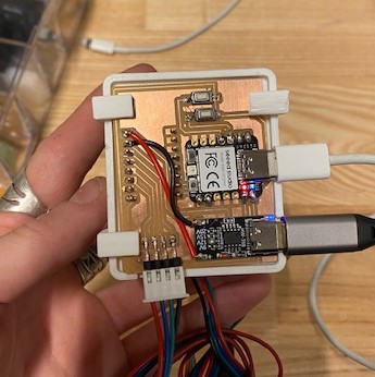
and luckily it all fit together! then i loaded the code onto the microcontroller, and... it works! you can see that it's loose and slips out a bit when inverted.
obviously i wanted to do more this week, but i really felt i actually came quite a long way in my understanding of circuitry, diagramming, and planning and executive electronics projects. i focused this week in the end on centering good design methods in kicad, about soldering and approaching new components, about parametric design for housing and thinking about kicad footprints in 3d, and more about digging deeper into circuitry in general! i really feel like i've come a long way the last two weeks, from feeling like i couldn't do a single thing, to feeling like i can figure it out if given enough time... (also jake, and quentin, and leo don't hurt either!)