Electroinc Circuit Design
Group Assignment
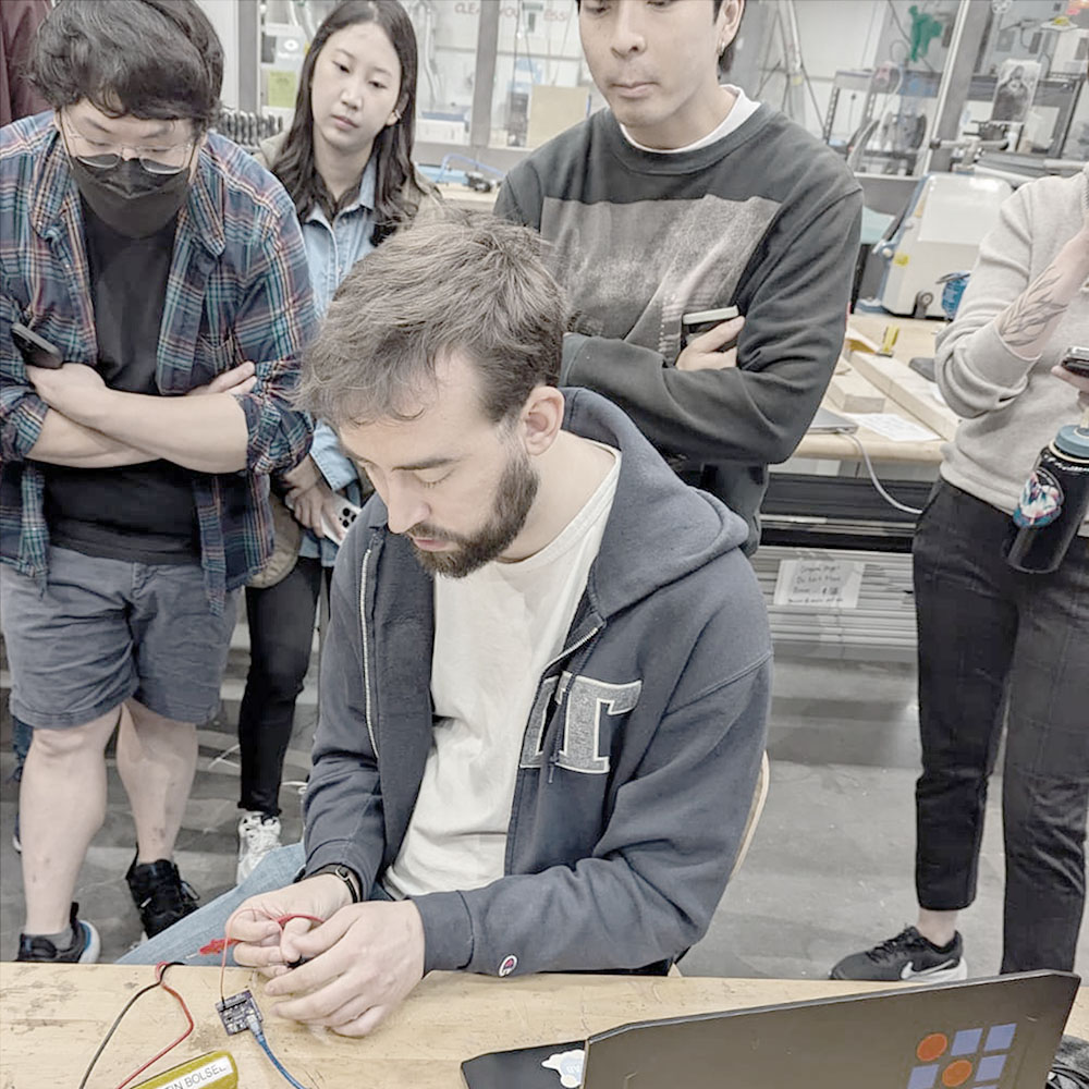
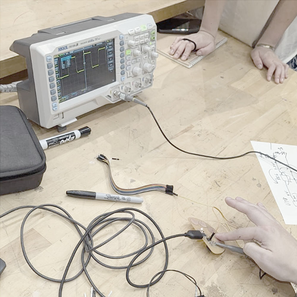
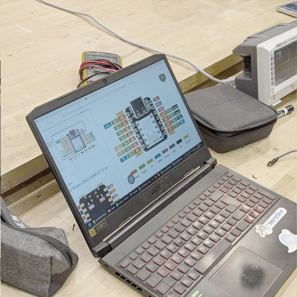
Quentin showed us how to test out circuits.
Using the lab's test equipment.
And also introduced the Xiao boards.
Iterating Over Components and Controller
I started working with the final project in mind, looking for a board that will connect to a locker and will allow taking a picture of what's inside, opening it with a keypad, and moving a servo motor for locking and unlocking. Also, it had to have internet capabilities.
After watching the video from last year, I realized I have no idea what a connector is or how to start approaching this week's assignment. Luckily, my dad was available for a Zoom call, and after years of refusing to play with the electric circuits kits he brought us home when I was a child, we finally had some electronics quality time.
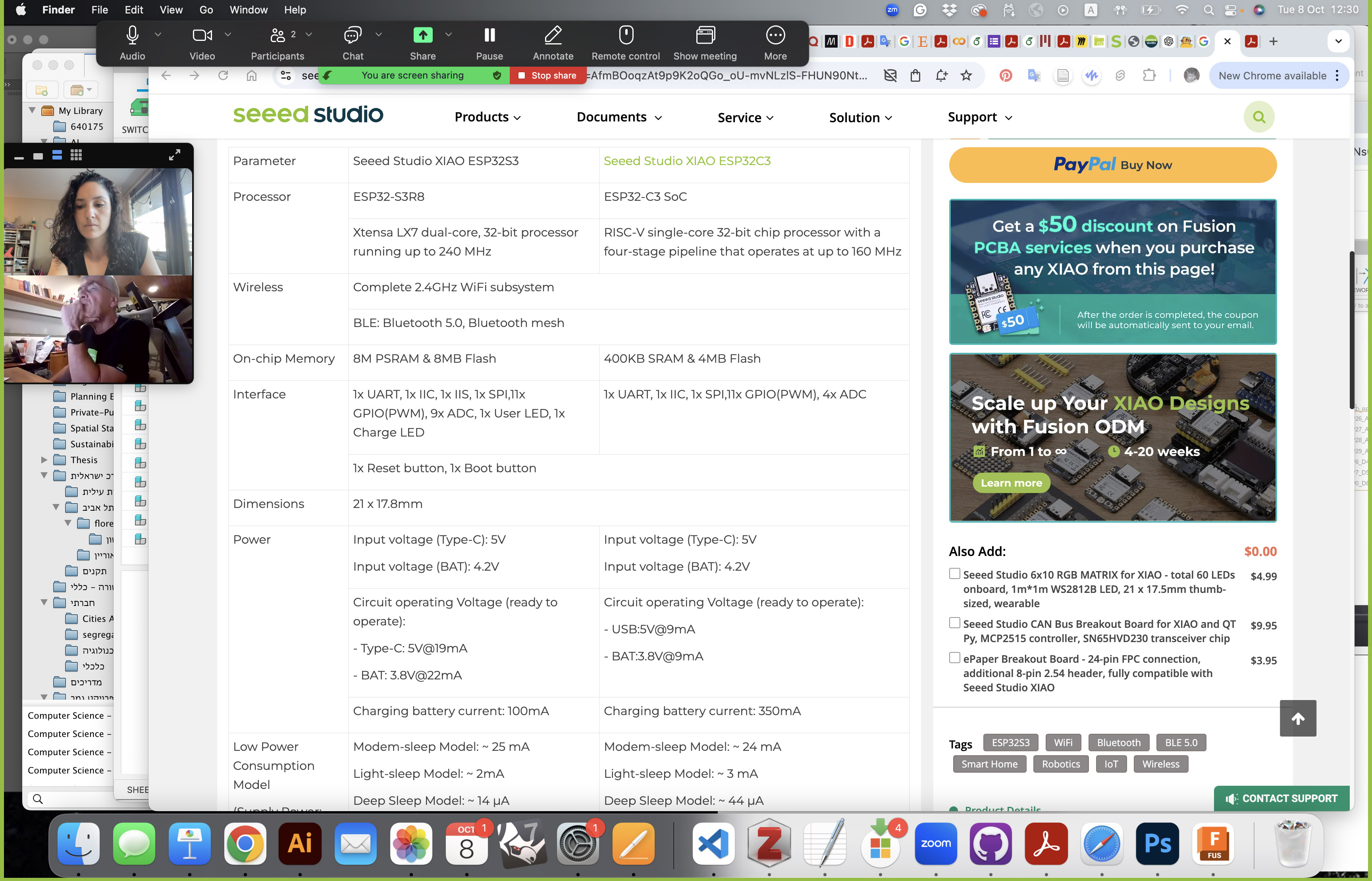
I ended up switching the ESP32-3C with a ESP32-S3 (both on the Xiao board), that could more easily support a camera as well a servo motor and a keyboard, despite being more expensive.
Then, I looked up the parts online on the Digikey website, and ordered them from them and from Amazon. Although the class inventory has some connectors and transistors, I rathered having a specific solution in some cases (like a 7-pin connector in one row for the keyboard connection). It was an iterative process of designing the circuit, according to the brainstorming I had with my dad, finding the right components in stock on Digikey, and then consulting with good old ChatGPT regarding whether or not they'd fit my purpose and how to connect them. It helped me find out, for example, that I'd have to use a resistor when connecting a led light to the controller, and calculate how many Ohms will be sufficient for that. It also helped me calculate the lumens necessary to light the box and take a picture from whithin it - a calculation I was somewhat familiar with from undergrad but had completly forgotten the specifics of by now.
Here are the components I ordered and will use for the board:
- Xiao ESP32-S3 with a camera component
- SG90 Arduino Servo motors
- Samsung LM301Z+ Leds in a neutral white color (3500K)
- Keyboards 3x4 matrix
- 1x7 through hole connectors (for the keyboard)
- 1x3 through hole connectors (for the servo)
- 8.2 Ohm resistors (for the led)
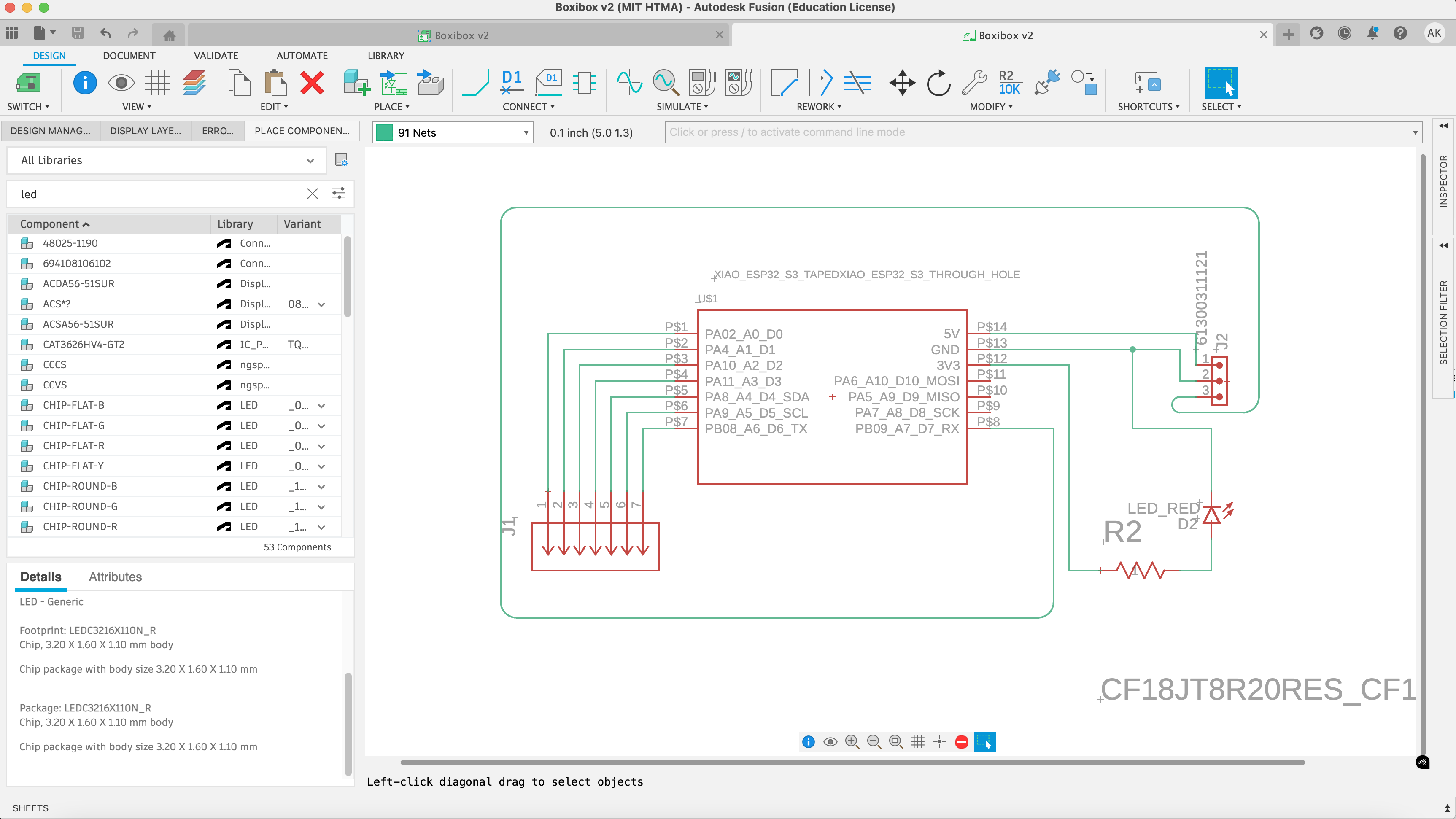
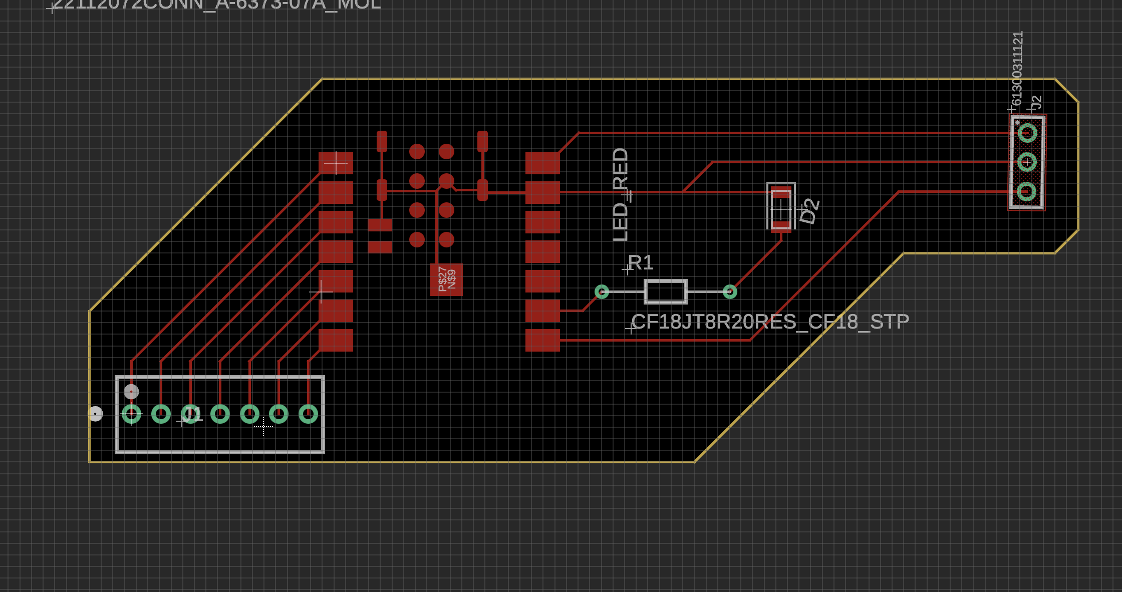
Design
I made the design on Fusion, and it's available on our class's joint directory. Digikey was lots of fun in that sense, because most components had a good EDA models I could download for my design - so I could actually design with the real parts I'm going to use.
I wanted to keep the Servo on one side and had to keep in mind the connection going out to the keypad going in a way that will allow me to deploy it on the door of the cabinet.
The minimal distance between traces on the board should be 0.4 mm, I made the lines a lot more far apart - following the connectors.