Electroinc Circuit Production

Group Assignment
We started off by getting to know the PCB milling machine we have at the architecture workshop. It is a Roland SRM-20, and we are working on it through the old Mods interface.
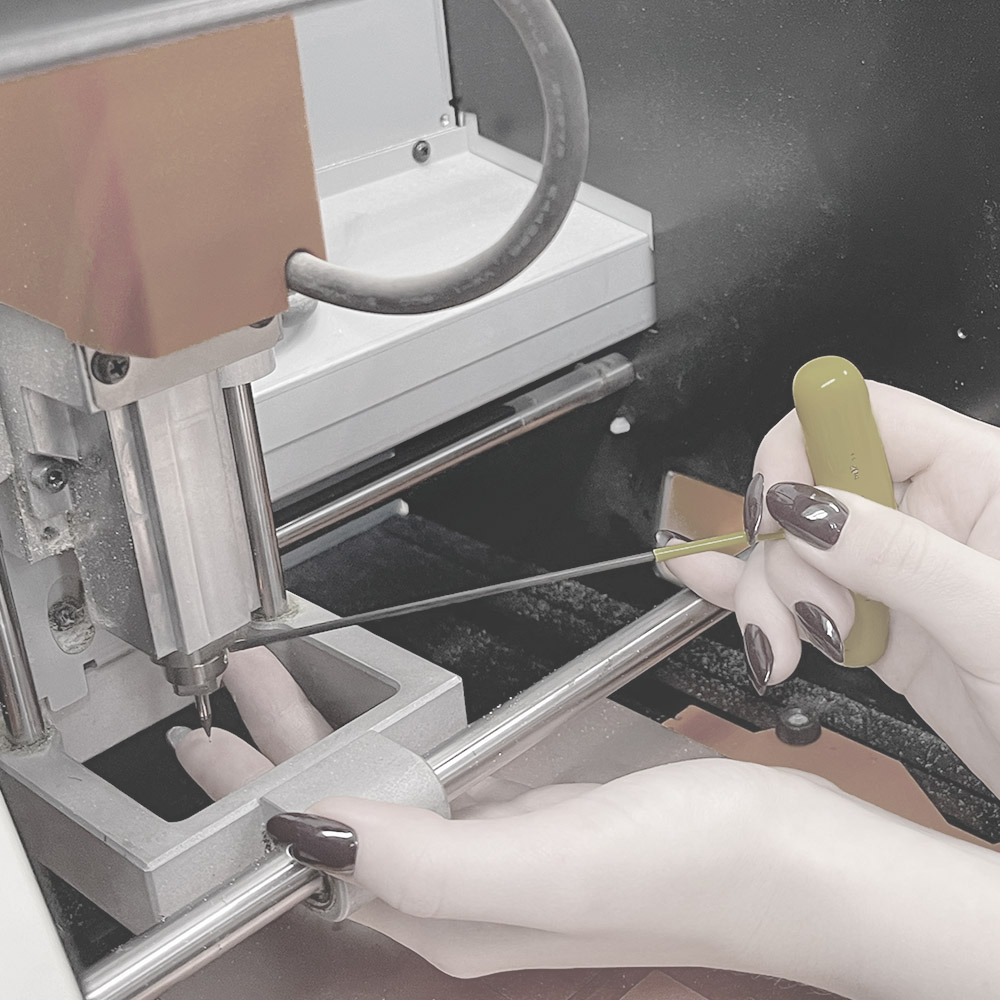
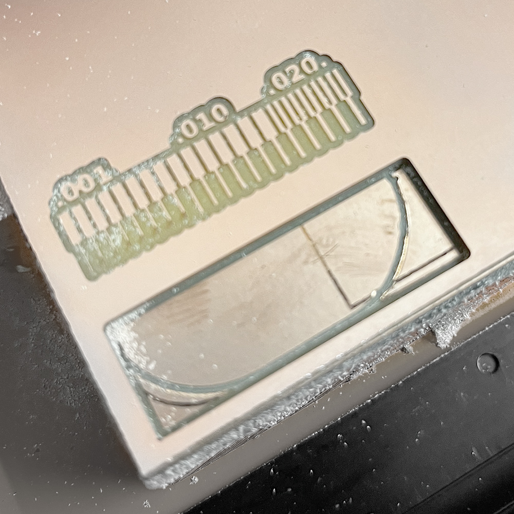
We went over the basics of the files needed for production and how to change the drills for traces (1/64) and outline (1/32).
Then we printed out a test file to check the minimal width for gaps and lines on our boards.
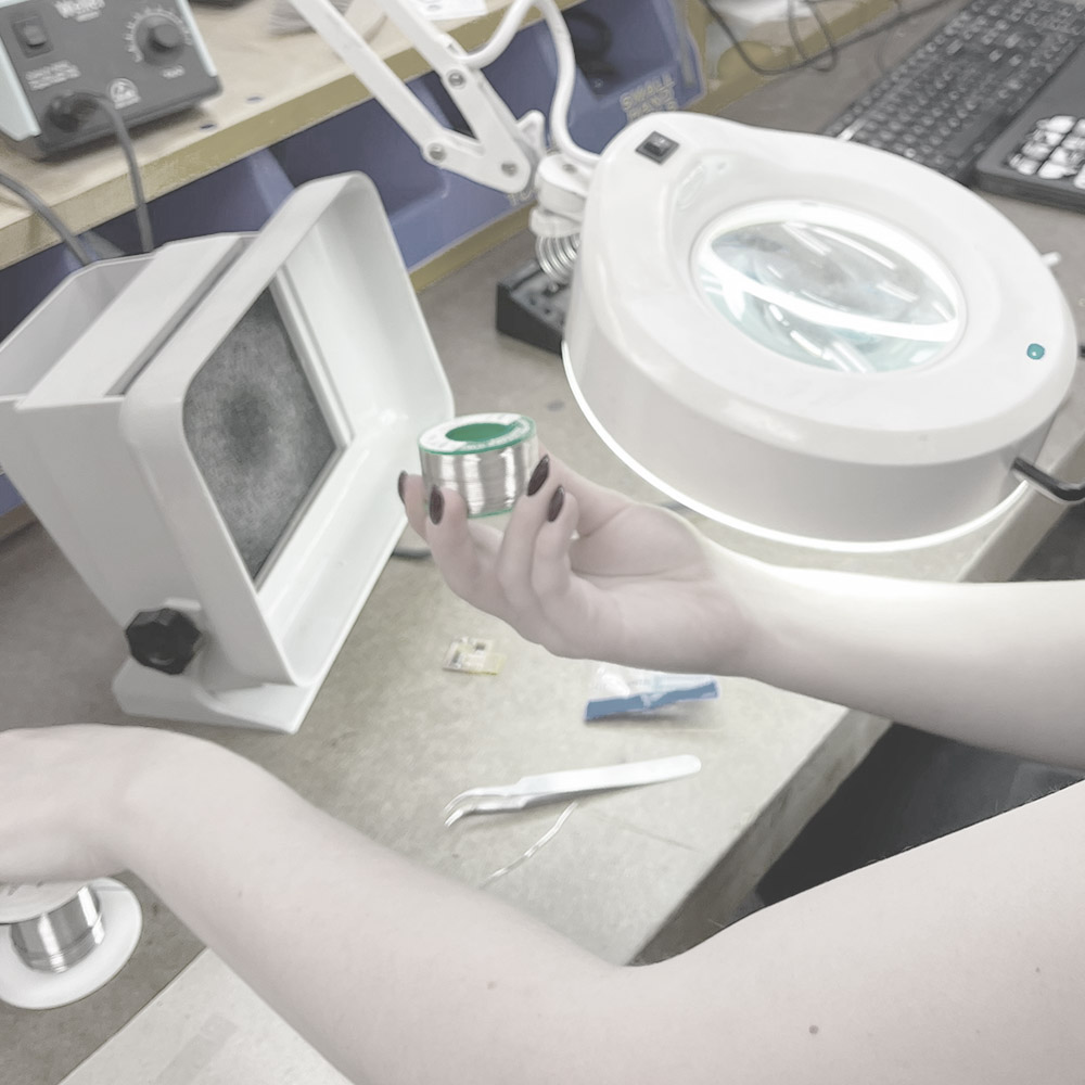
Finally, we practiced some soldering, paying attention to choose the non-lead wires.
Milling my Board
This was a disaster. I made lots of stupid mistakes and had to go through 4 iterations. After exporting the files from fusion in a gerber format, I ran them through Quentin's web-app for converting them to BW images, after that I also found out (the hard way) that I have to resize each of them to make sure they all come out in the exact same format - so I did that in PS.
After long iterations of trying to get the connection between the mods and the milling machine to work, I ended up succeeding in milling but failing in doing it correctly. The drill holes for my through-hole soldering, were cut way to wide and got connected into one long useless slit.

Apparently, after talking to Anthony, I realized my file was wrong and instead of having the circles' outlines, I should have had then drawn as blank full white circles.

Next, I lost the connection with the machine and had to restart the mods. Allas, I forgot what was the origin and had to start over. In the third iteration I forgot to switch the drill back from milling to tracing and ended up excavating my board instead of tracing it, and on the last one - I finally got it. Not after also realizing the full circles weren't enough and that I also had to invert the png on mods to get it to drill the holes on the inside of the outline and not offset them out (another visit to Anthony's - thank you!).
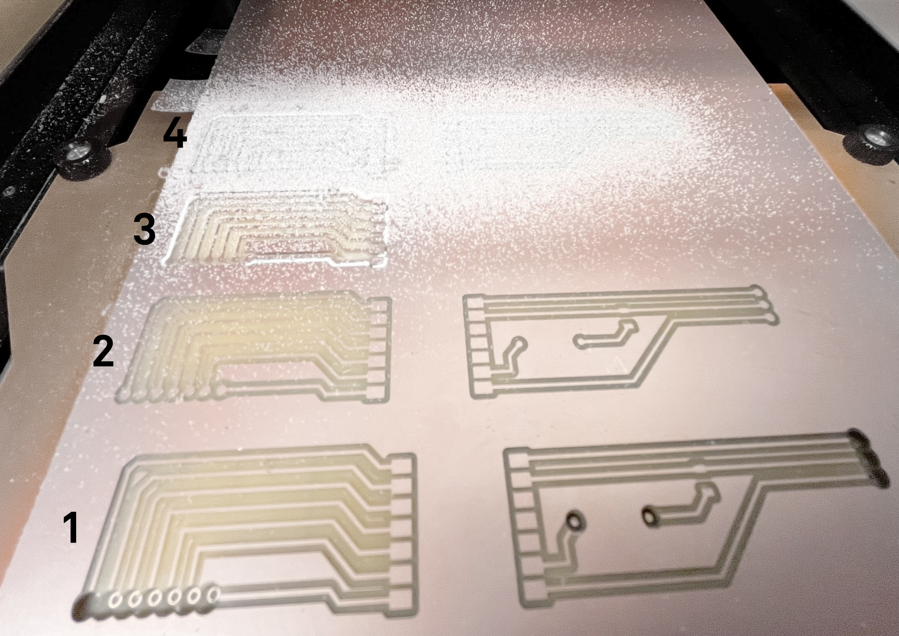
Finally, I had a ready milled PCB.
Soldering
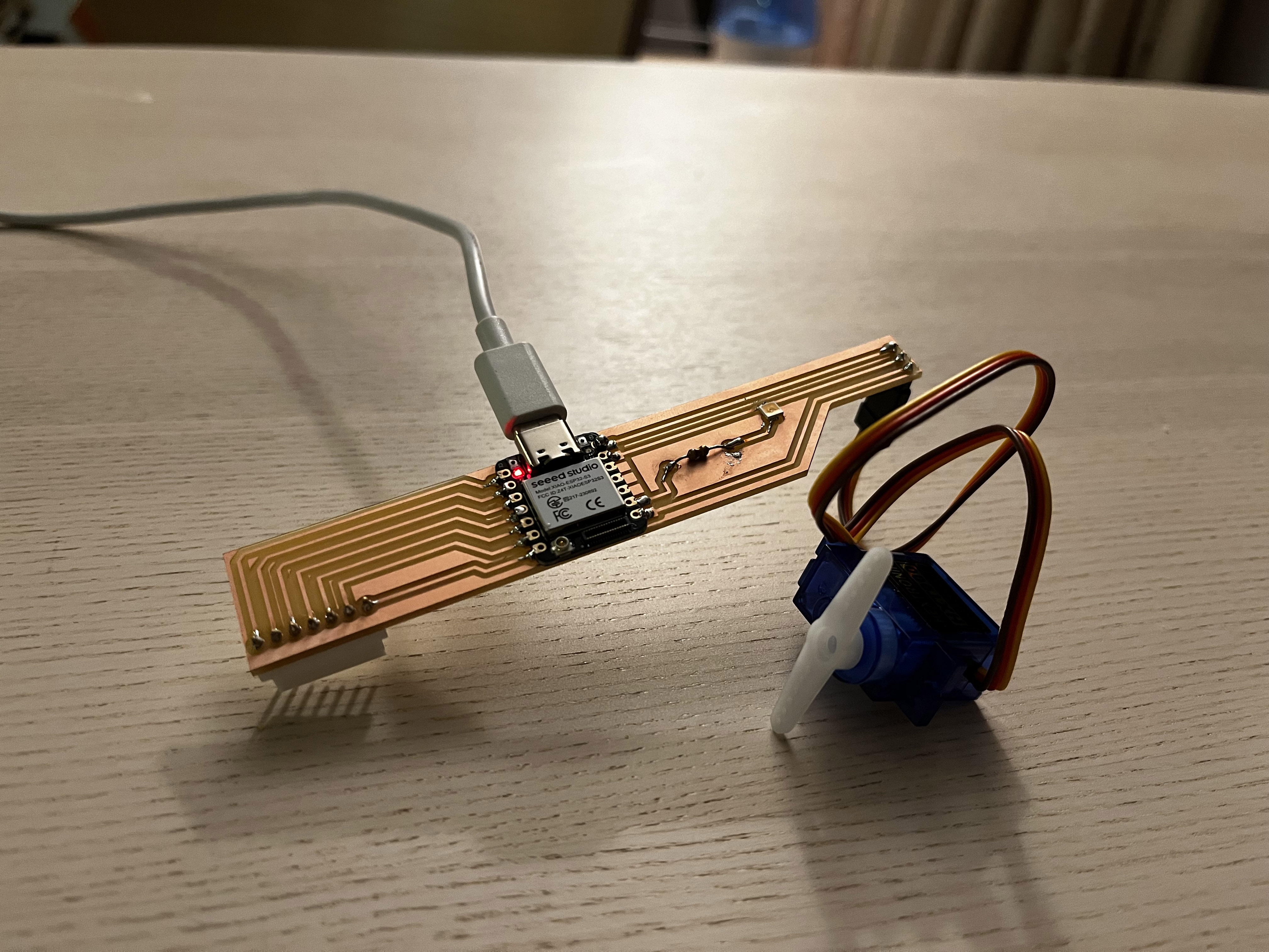
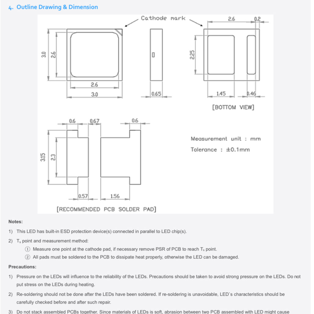
I soldered the components I had beforehand - so all of the connectors, the controller and the led. The led was a bit tricky to understand which side is the cathode and which is the anode. The datasheet (and Anthony) were helpful for that end.

Testing
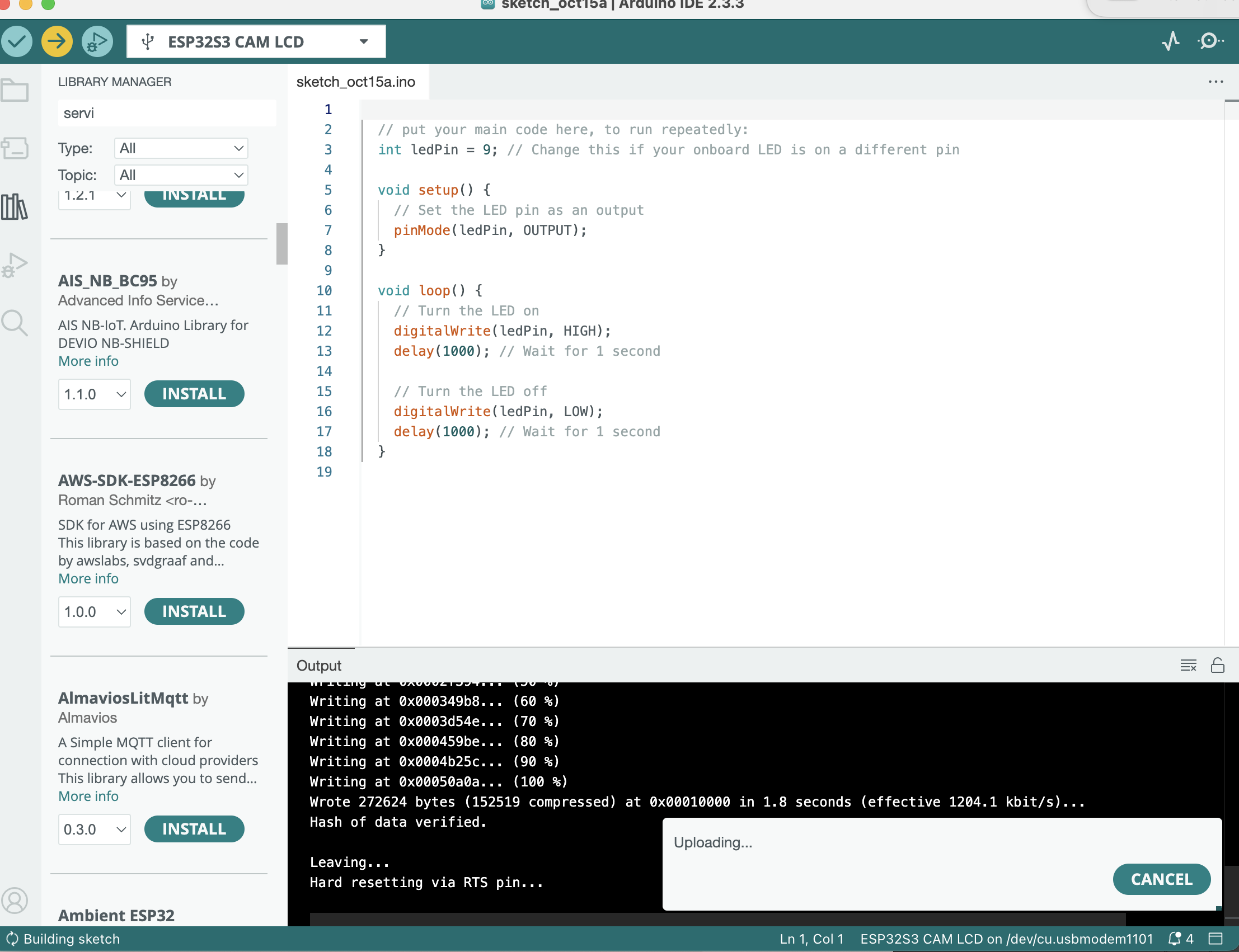
I used ChatGPT to get started on how to use Arduino software with the ESP32-S3 controller. It didn't work - I tried out the led and the servo controller. Here is a list of debugging actions I tried taking, none of which worked:
- Putting a piece of paper between the controller and the board to avoid it shortening because of the bottom conductors.
- Inserting debugging statements into the code (none showed)
- Replacing the cable (I initially used a noon-data one)
- Re-connecting the Servo by manually switching the lines on it because it wasn't initially well-connected
- trying to manually bypass the connection I wasn't typing the right number of the GPIO.
