Output Device

Re-design the PCB
For this week I started by refreshing the board I made last time, because (1) it had a problem of the Servo's pins not being in the right order (I worked around it by manually switching them but it wasnt' ideal), (2) I had to add the camera and replace the ESP32-C3 with the ESP32-S3 and didn't want to burden the board with another round of soldering-desoldering, (3) after experimenting with the previous board, I realized users could really use an indicator led that signifies whether they input the correct code into the keypad (green/red light), (4) I wanted to optimize for the way the board will "seat" on the door of the cabinet in the final project, which meant changing a little the orientation and the location of the keypad and the servo.
So I started by redeisgning the board on Fusion 360, adding the two leds and utilizing all of Xiao's pins (exciting!):
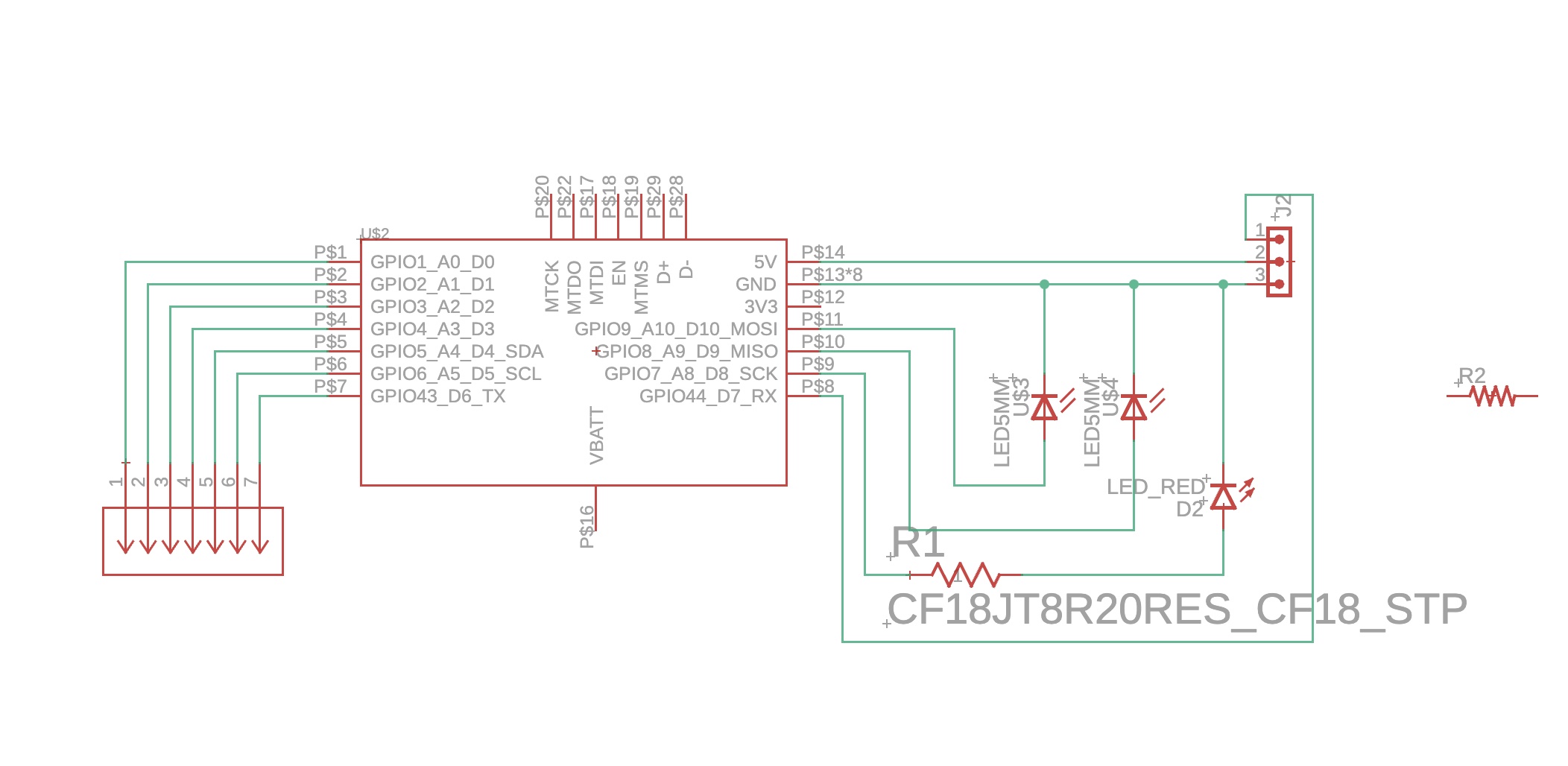
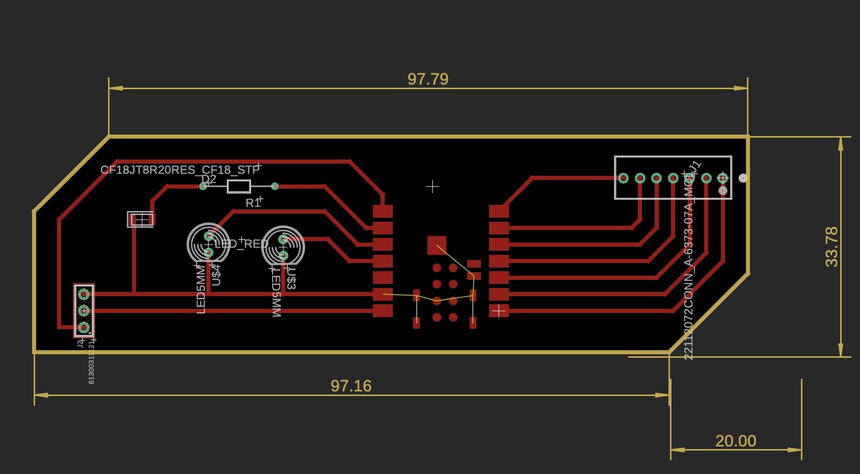
In the process, I also made sure the leds I got from Anthony would fit in the new holes I was about to make. So I made a trip to the EECS shop and got the red and green leds, and a new set of connectors I could use for the keyboard and the servo which don't need through-hole soldering and will allow a better placement of the board against the door (without as many components sticking out).
Re-produce the PCB
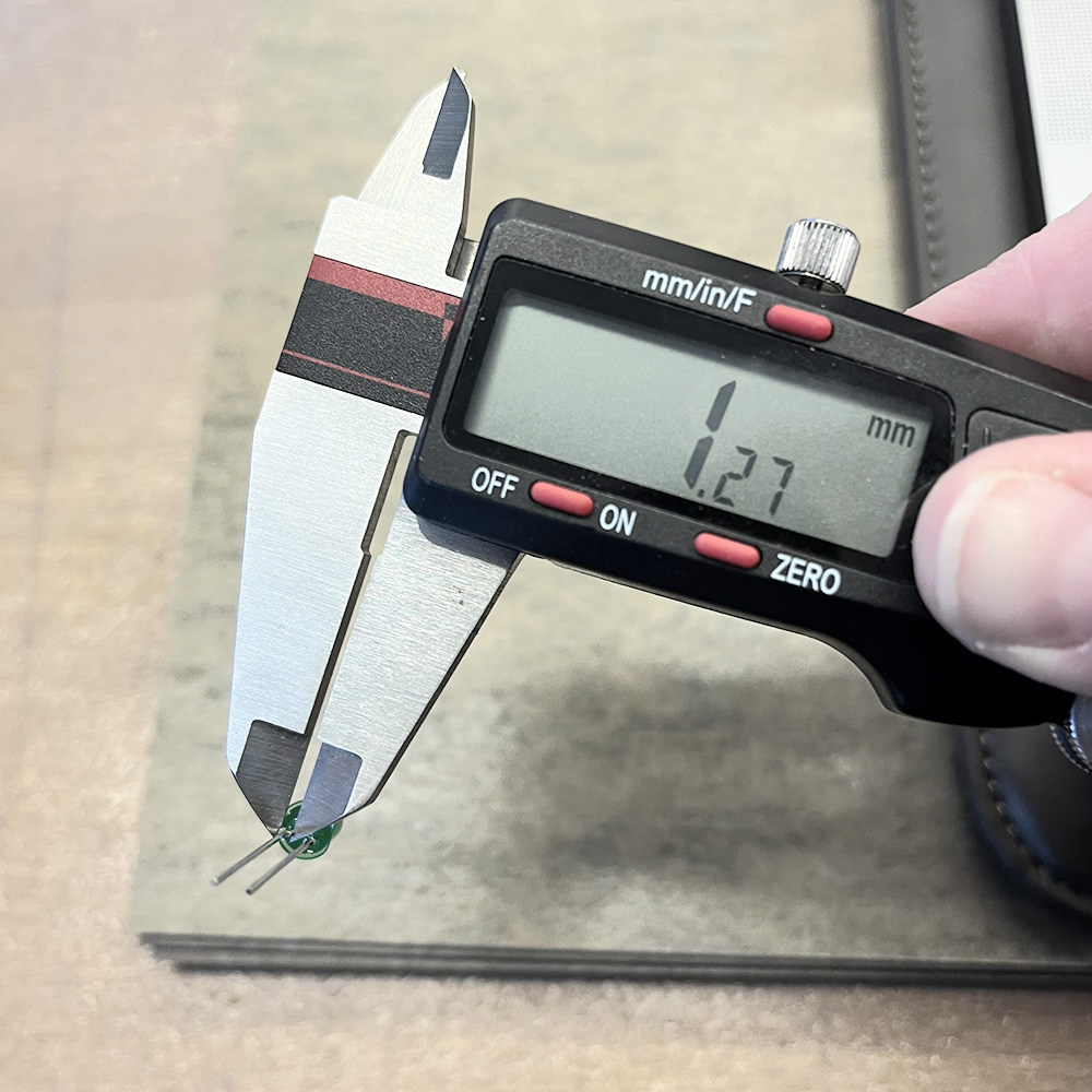
Using a digital calliber to measure the leds "legs", I quickly realised I could also cut them off above the bulgy part.
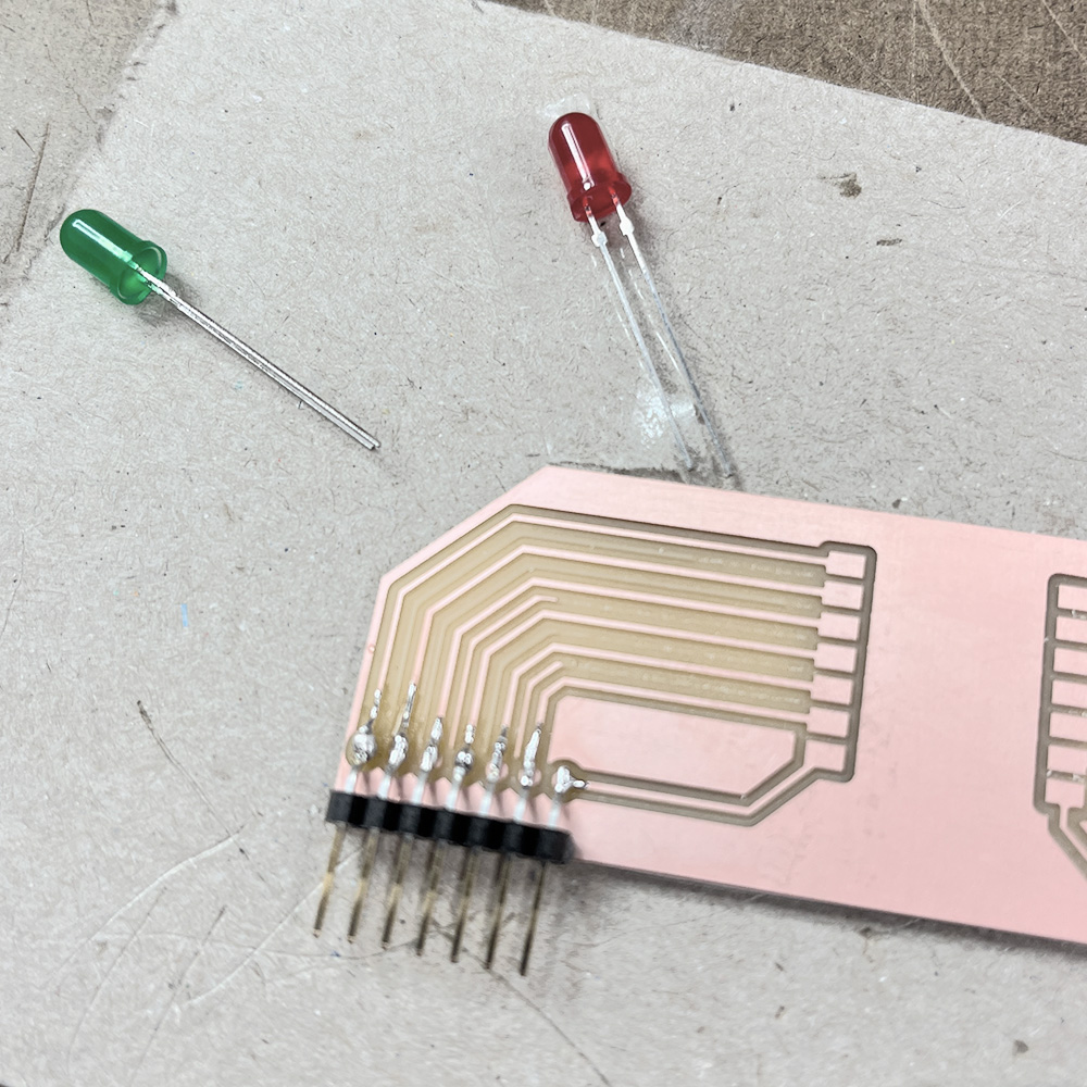
New leds - red for wrong and green for right code inserted on the keypad, and connectors that can be soldered on-board.
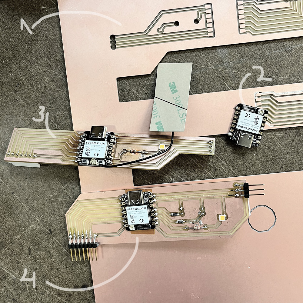
The boards I milled wrong (1), the Xiao I fried (2), the board I re-soldered with a Xiao ESP32-C3 (3), and the final one (4).
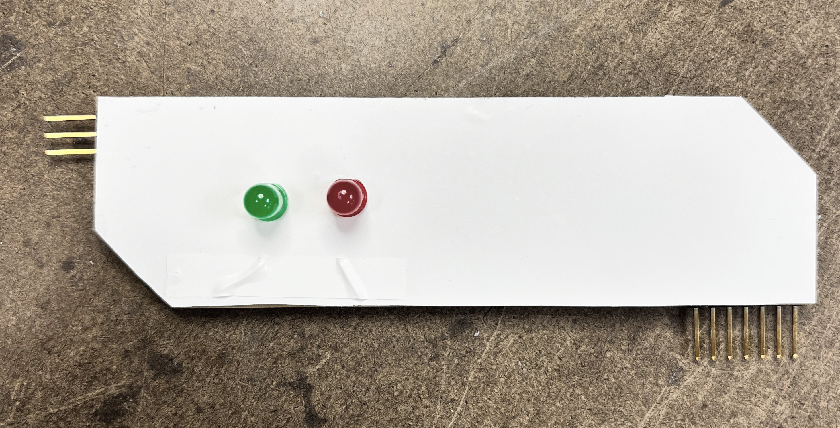
I also put some white vinyl at the back of the board to make it nice and tidy:

Embedded Code and Testing
After soldering, I wrote a code snipppet for the Xiao, taking the code from the keypad as input, checking if it's correct - if it's correct the green led lights up and the servo moves (opening the lock of the door), also the led light on the inside lights up to prepare for taking a picture of what will be placed inside with the camera. If the code is wrong, the red led lights up and the servo doesn't move, nor does the strong led ligths up.
ESP32-S3 Camera Feed
For the next step I tried to get the output from the Xiao ESP32-S3 Sense camera but went out of time. The plan was to get the camera feed on the website, and then integrate it with the keypad input. I ran into a lot of difficulty connecting to the camera at all from my home wifi in the dorms or on my cell's hotspot. It worked eventually when I tried connecting through the EECS's lab designated wi-fi for IoT, but I need a more robust solution that will allow connecting to the cameras when I place the final cabinet in the housing's loby.
This dissapointing square is where I got this far with getting the image from the camera:
For the next step I will make a PSK request from MIT's IS&T to connect to MIT's network directly from the camera and try again, following Anthony's recommendation.