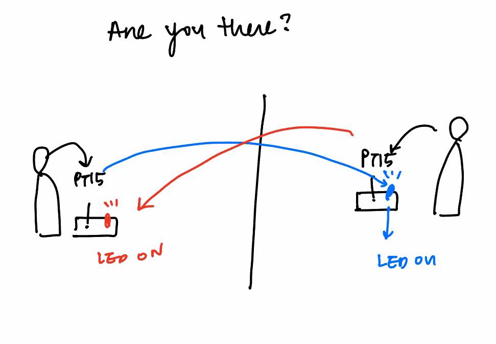
This week I started the week by making another simple version of the final project (for easier pcb fabrication since I am new to it). I decided to test if two users (at different location) are near the device, the device will turn on to let the other person know that their partner is “present.” (the switch could be used to communicate, but that is still tbd).
Summary of how this would work:
Step 1: If User 1 is present near the device, User 2’s LED turns on (and vice versa)
Step 2: User 1 can use the switch to communicate
Therefore, I need to figure out:
1. Create a functional PCB board design (check)
2. Learn how to send code to the microcontroller
3. Figure out a way to communicate through wifi

For the future reference, this was a helpful diagram that I found that deals with PT15 21B. Architecture shop had both 21B and 21C for PT15 and here are the differences:
21B: 730-1100nm (often used for IR sepctrum)
21C: 530-1030nm (often used for visible light)
Upon a quick Google search, the human body emits radiation in the infrared (IR) region of the electromagnetic spectrum, with most of it at a wavelength of 12 microns. IR radiation has a wavelength between 780 nanometers and one millimeterI decided to go for 21B.
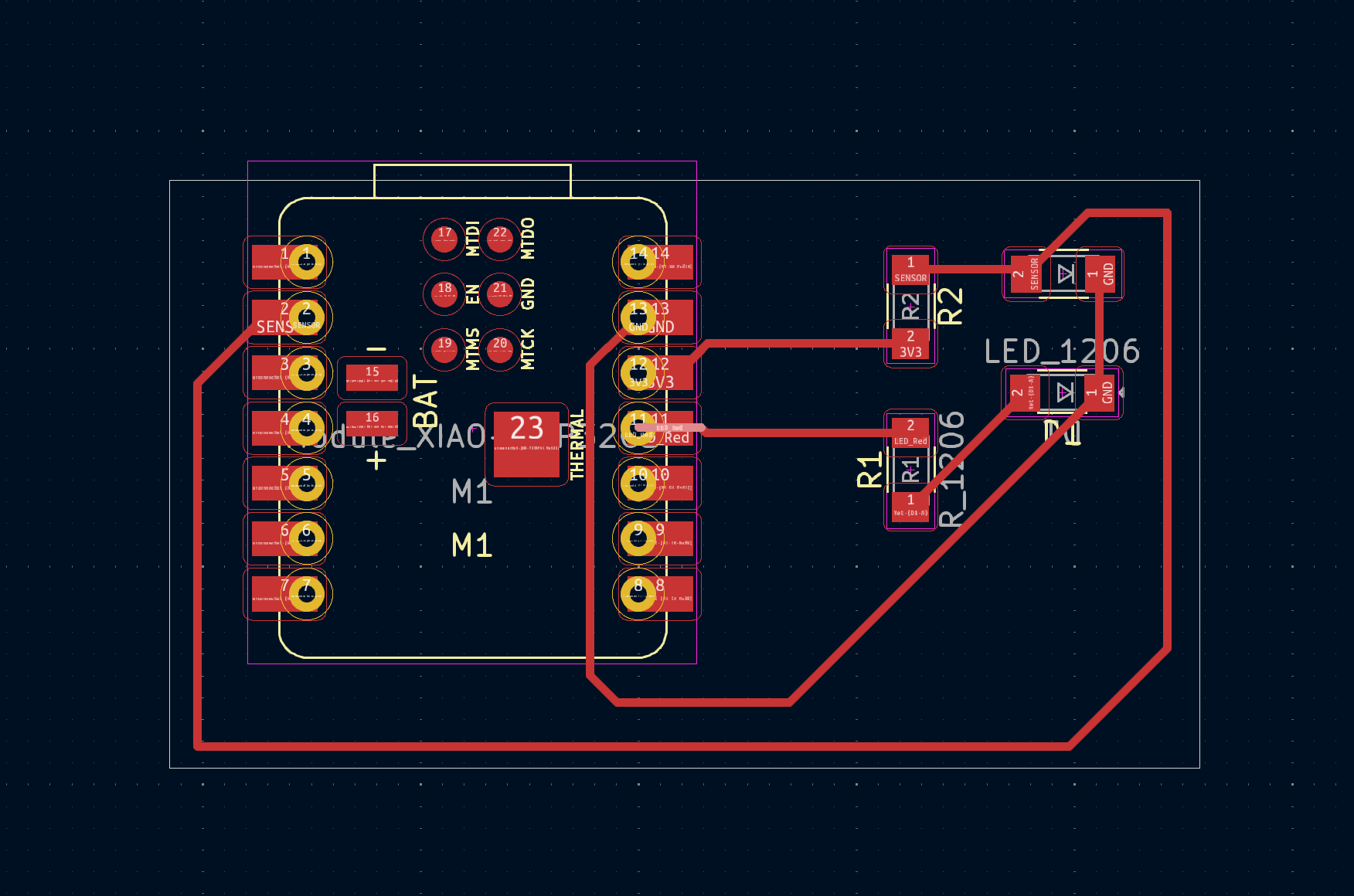
This is what the PCB designed looked like
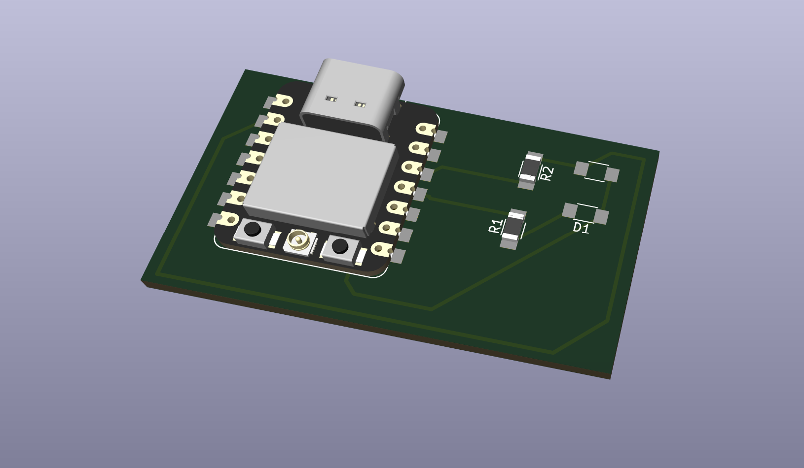
This is how the PCB looked from the 3d view (PT15-21B/TR8 and LED are missing)

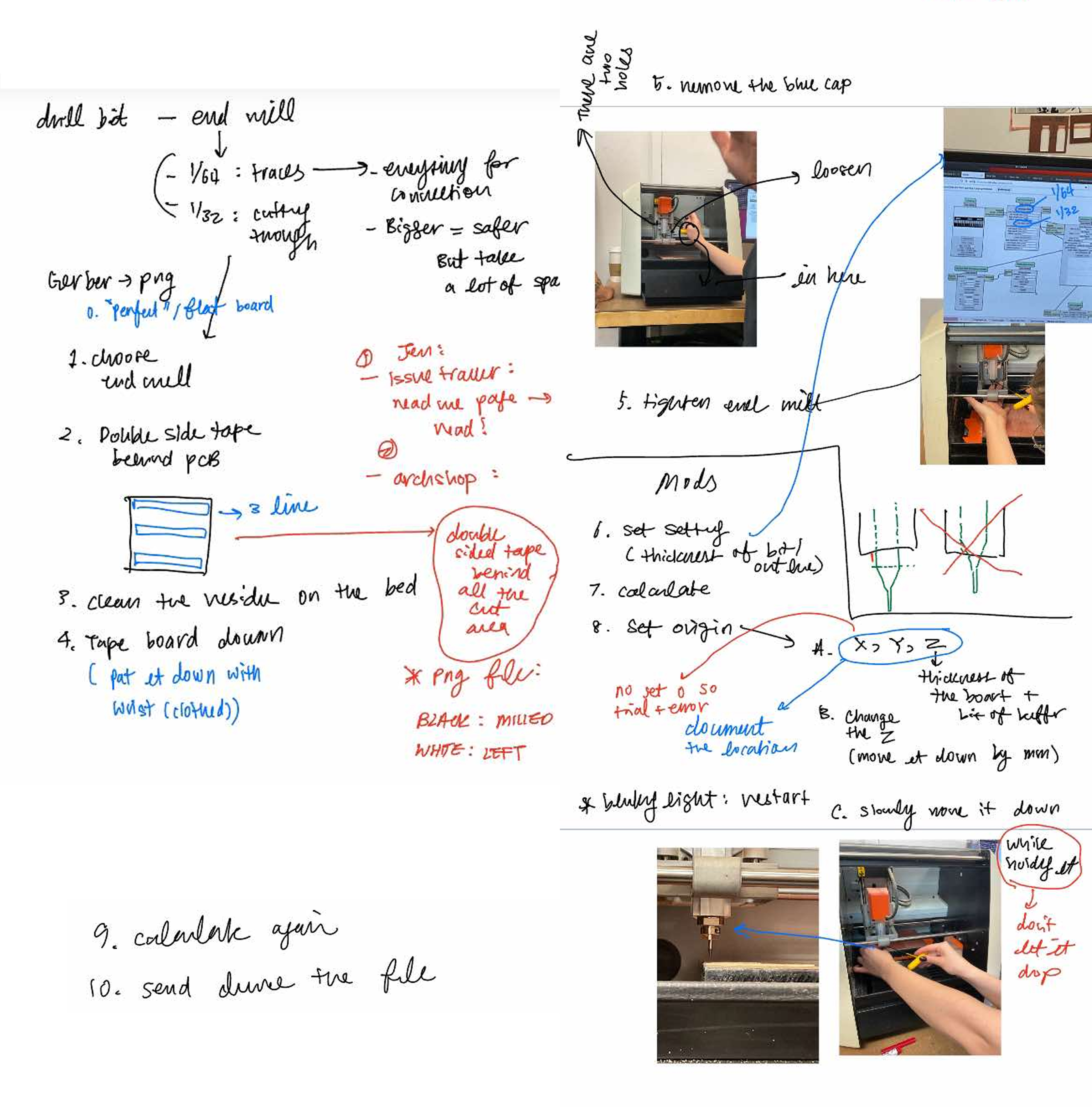
Using the Gerber2img converter, I prepared the png file for milling

I am regretting how boring this outline looks like, but please refer to last week's assignment for my more adventurous attempts with pcb shapes.
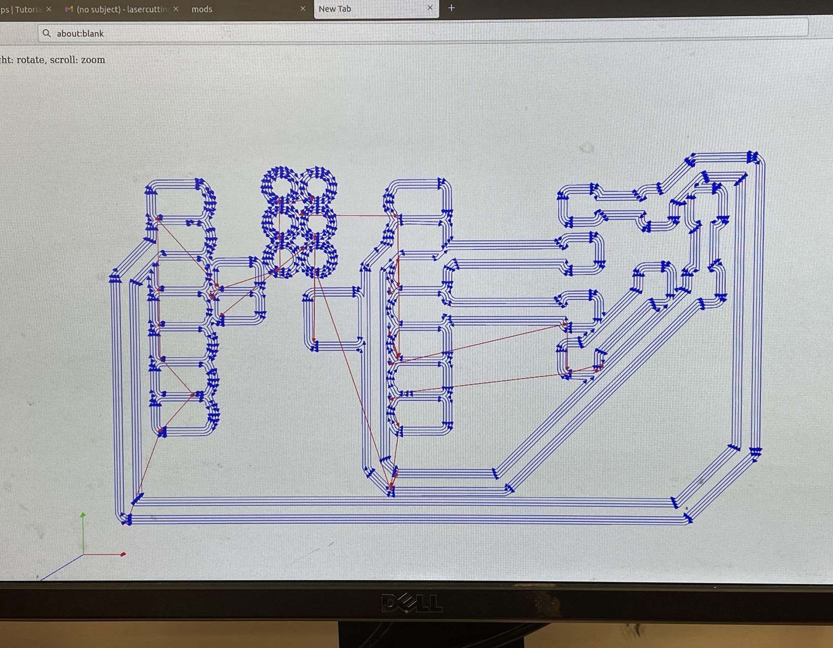
Using the Mod, the toolpath of the png file looked like this.
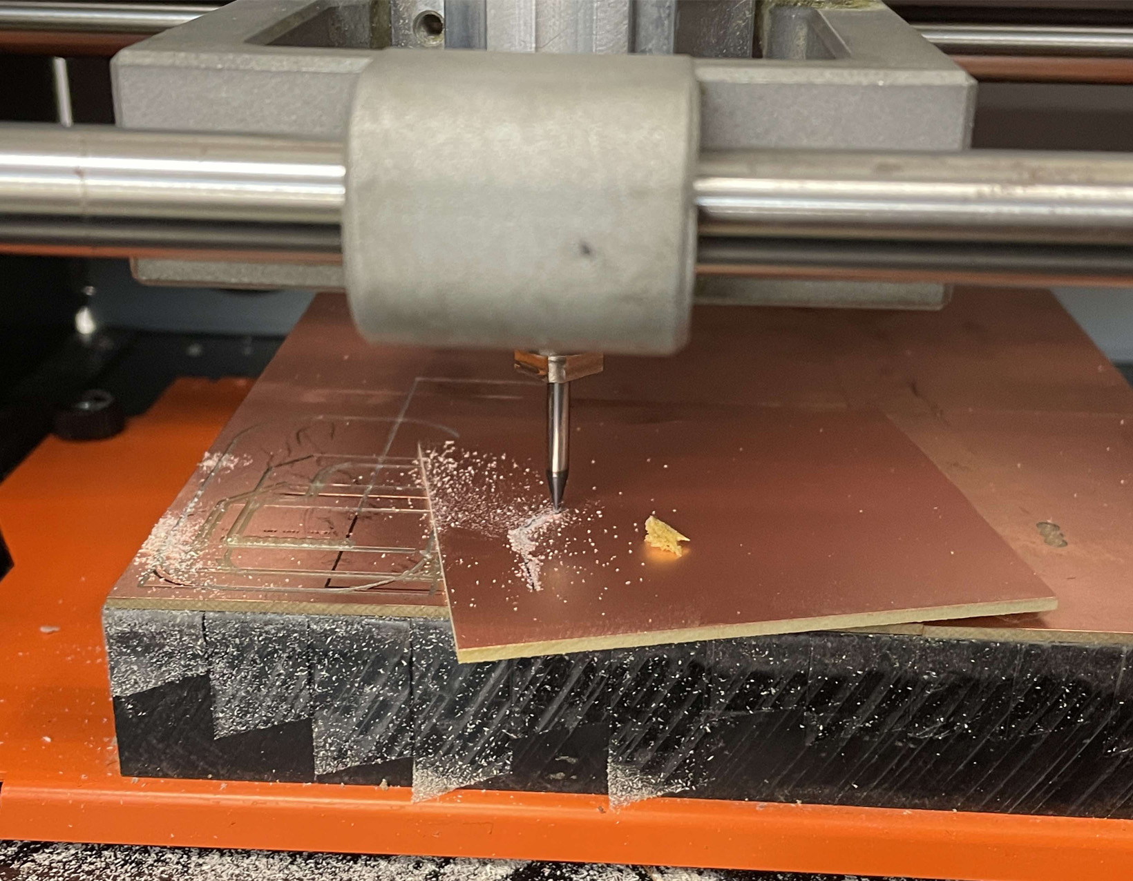
For the first attempt, the board was not attached to the bed firmly and the drill bit started to drag the board around.
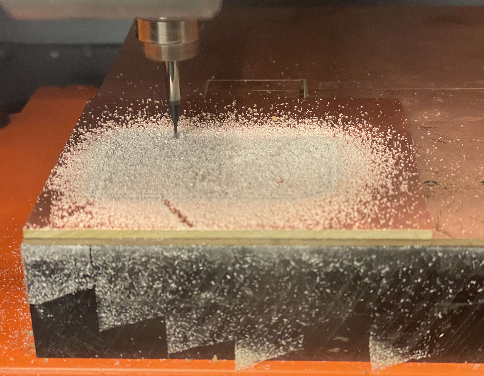
The second attempt was more successful. I realized the edge cut line is actually not centered to the etched part of the board. Jacob noticed when you convert Gerber to png, you need to make sure to fix the position. However, for my board the lines seem to be all connecting, so I decided to continue with what I had.
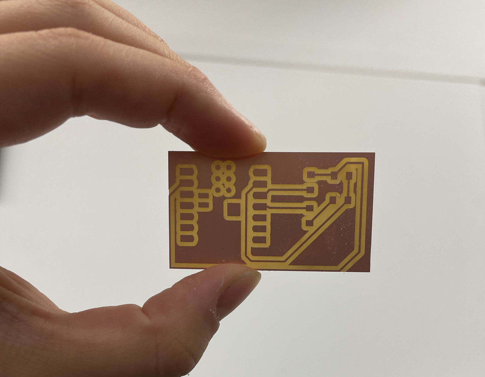
This is how the board looked like after milling. I milled twice for to make two boards that can talk to each other.
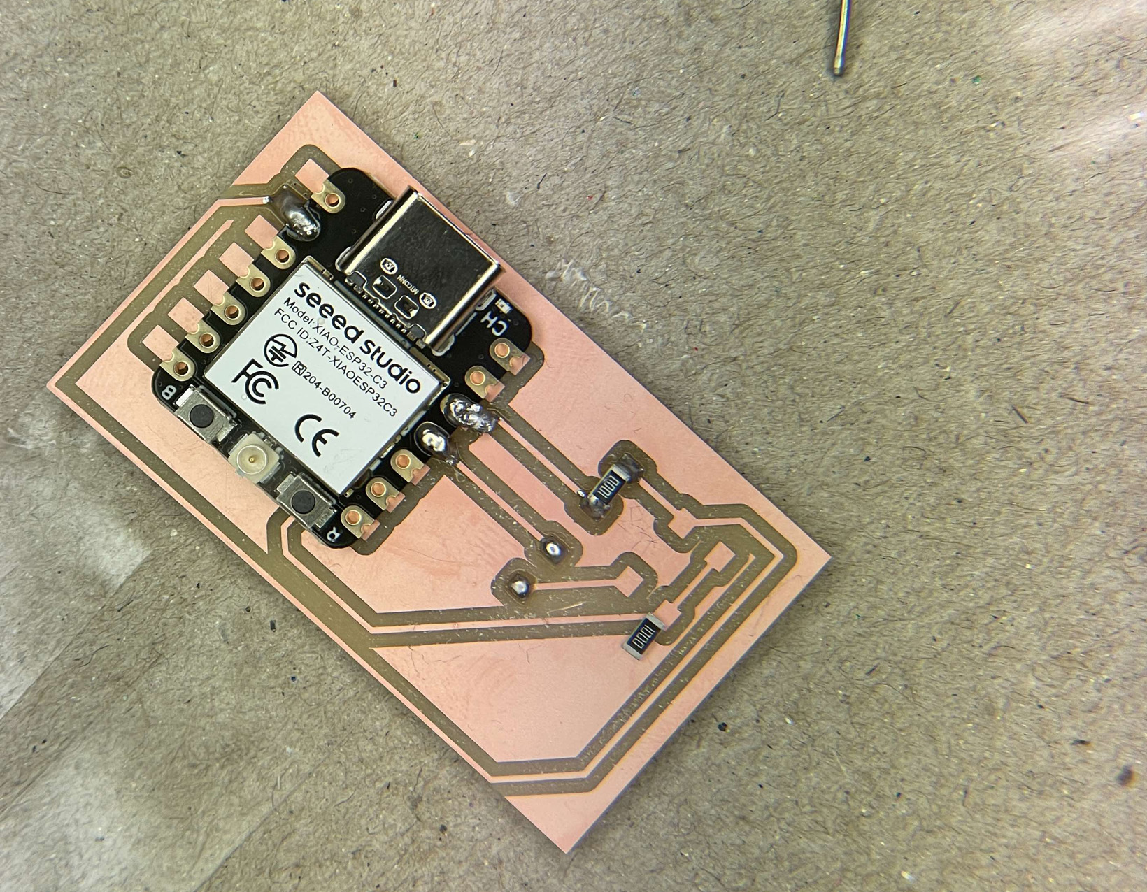
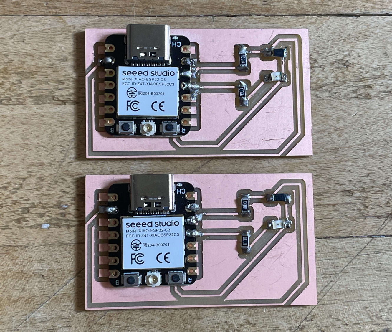
The soldering was a bit tricky, but Diana's technique of putting a bit of soldering material on the board before soldering the parts together helped a lot.
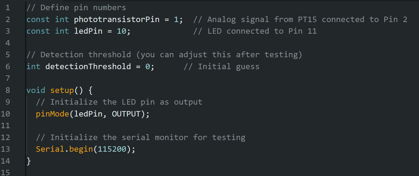
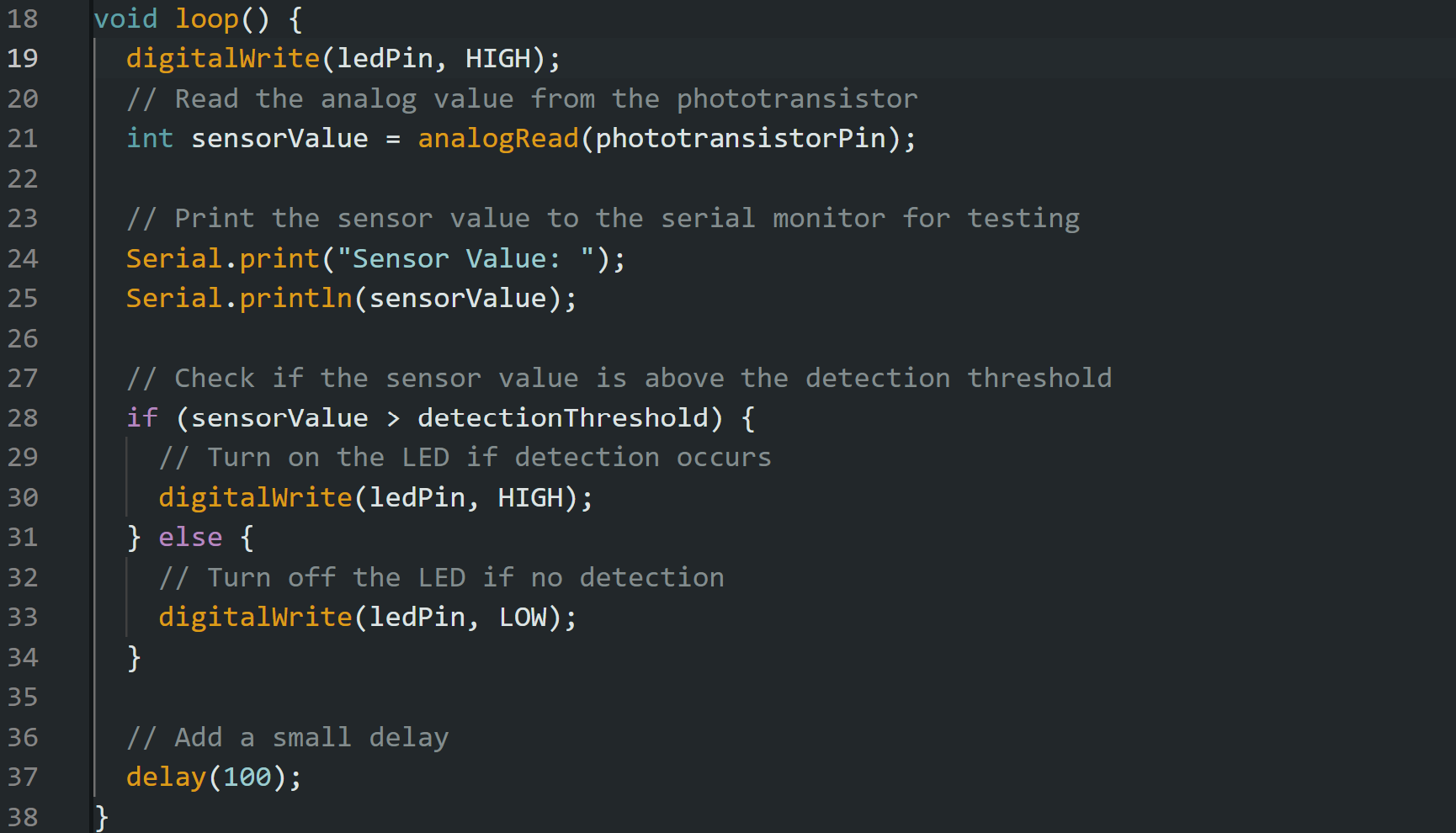
In order to test if the components worked, I wrote a script using chat gpt to turn LED on if PT15 sends signal higher than 500. The code is also supposed to take analog reading of the sensor pin to the serial output.
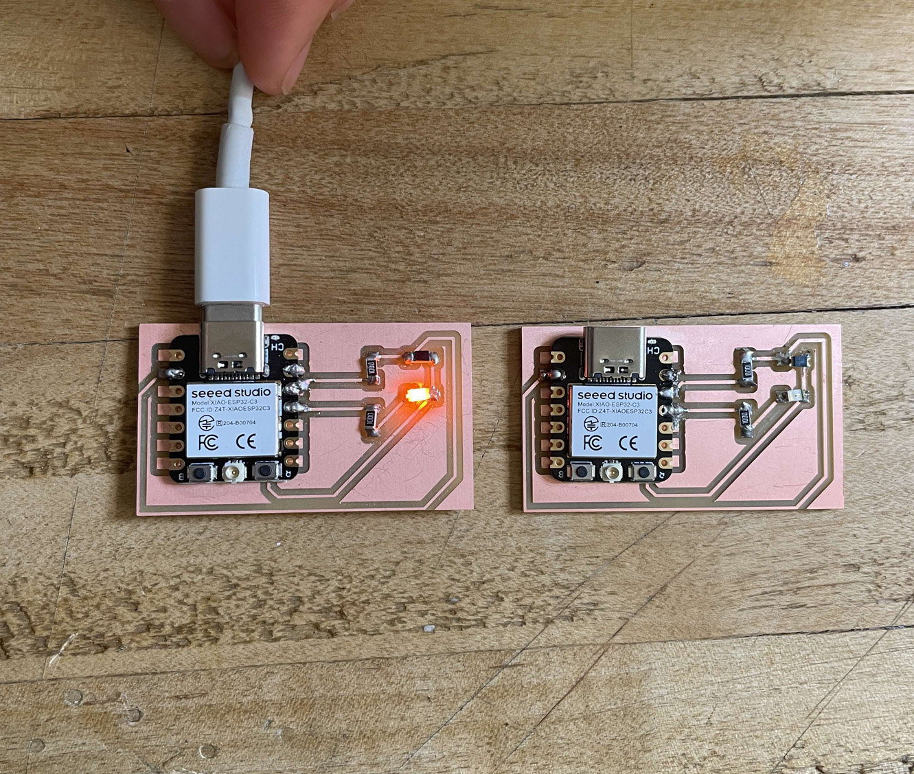
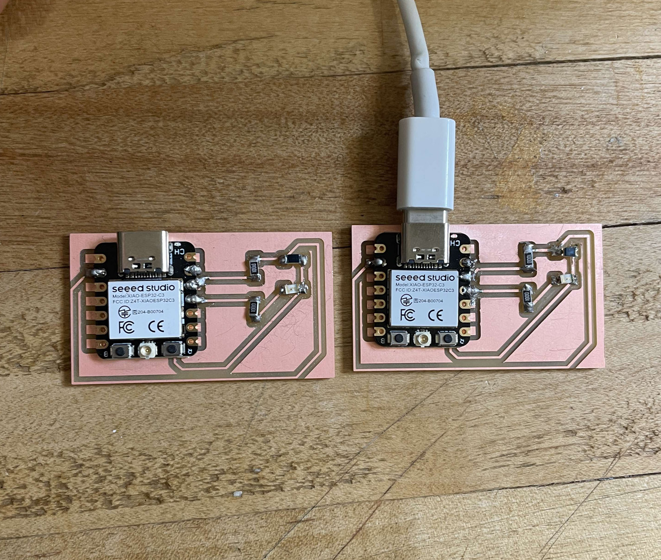
The LED worked, but PT15 seemed to be having an issue since it seemed to be turning the LED on regardless if I was close to the sensor or not. I was also not getting any reading from the photoresistor.
This is also when I realized if LED pin is right next to the infrared sensor, it is going to interfere with the sensor's reading (aka always will turn the LED on). The multimeter test seems to be working for both boards, but here are the current list of issues and potential tests:
- Immediate issue list:
1. LED is not working on one of the boards.
- The circuits are all connected and LED turned on with multimeter
- LED is connected in the right orientation
2. PT15-21B on both boards seem to be not working.
- Check the orientation again
- Check if the component expired?
- Redesign the board so the sensor is away from LED
3. Serial.print is not printing even when it is not related to the analog input.
- Not too sure what is happening here, but I have a feeling it is more of the code issue
4. Since one board is not working, I can't move onto the network stage yet (I'll try to solve the network issue later this week)
- try connecting to the network and turning the LED on remotely
