Group Assignment

I worked with Sara, Namirah and Anthony on the group assignment.
We elected to use a Seeed Studio XIAO ESP32 C3 microcontroller in order to complete the group assignment. We realized that in order to attach the microcontroller to a breadboard, we would have to solder in male-male connectors. Our group had limited soldering experience, but we each tried some, and our electrical connections seemed to be working properly.

XIAO microcontroller and male to male connectors.

Soldering in action.
In the Arduino IDE, we added the ESP32 board package. This allowed us to select the correct board and port and upload our code to the microcontroller as needed. We started with some very basic code that would flash an LED every half second.
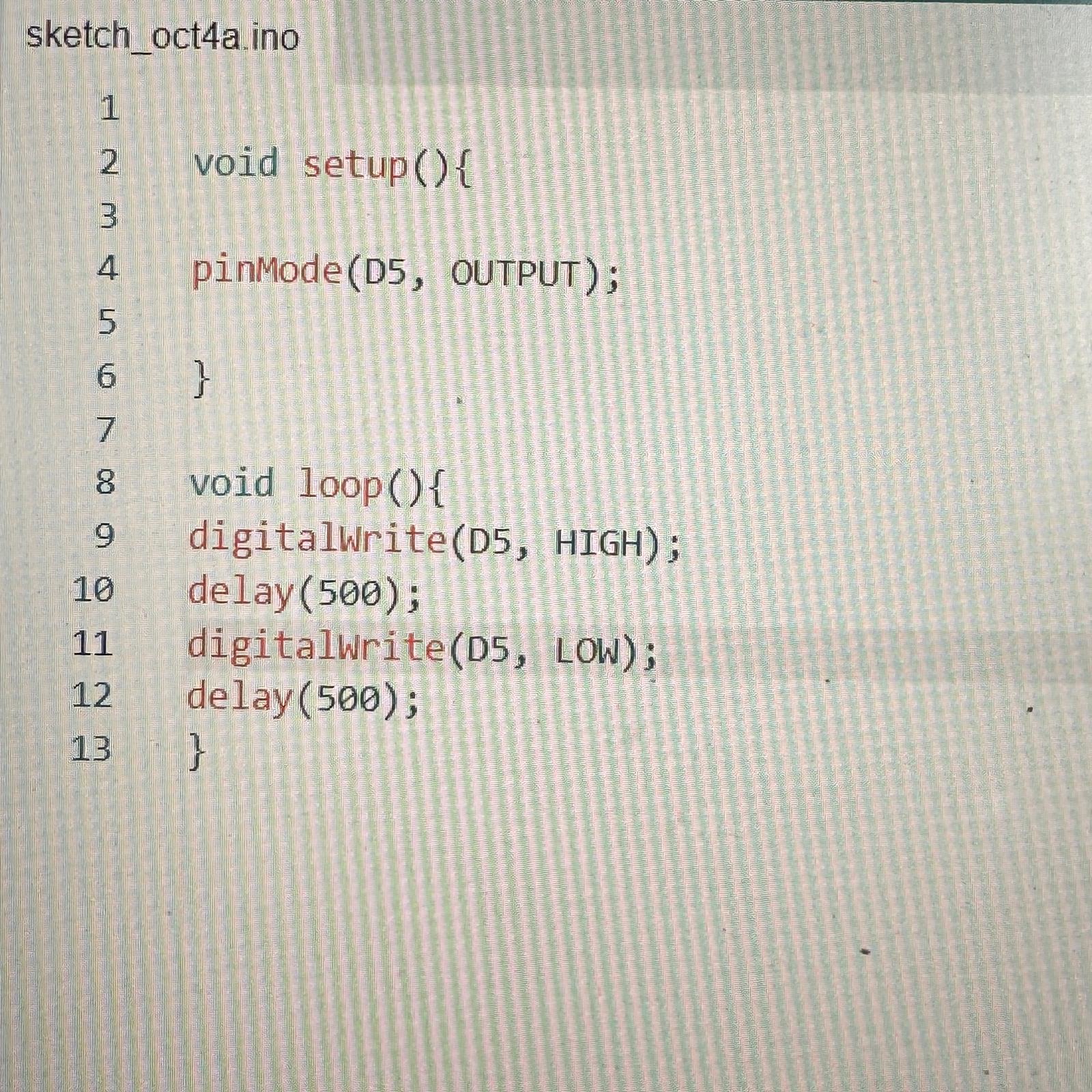
Code in the Arduino environment.
We then set up the breadboard with an LED connected to the appropriate pins and demonstrated that our setup worked properly. I later attached the oscilloscope to either end of the LED to observe the signal corresponding to the LED turning on and off. The result was a square wave, as expected.

Breadboard setup with lit LED.
Individual Assignment: Use an EDA tool to interact with an embedded microcontroller
To approach the individual assignment, I downloaded KiCad. My plan was to make a board that would provide the same functionality (lighting an LED) as the breadboard from the group portion. I first imported the part libraries provided by the class in order to find the XIAO ESP32 C3 microcontroller and use it in the schematic environment. I created a very simple schematic involving the microcontroller, a resistor, and an LED.

Schematic design of PCB.
I then opened the PCB editor environment in KiCad.
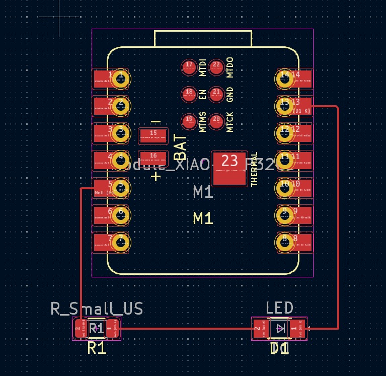
PCB editor environment in KiCad.
KiCad had a really interesting feature that allowed me to view my design in 3D. This helped me realize that at first I had selected the wrong resistor type.
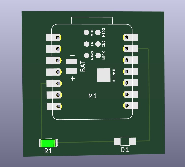
3D view of the design.
Finally, I converted my design to Gerber files. I chose to do this because it would allow me to upload it to JLCPCB, which I could use to purchase this PCB if needed.
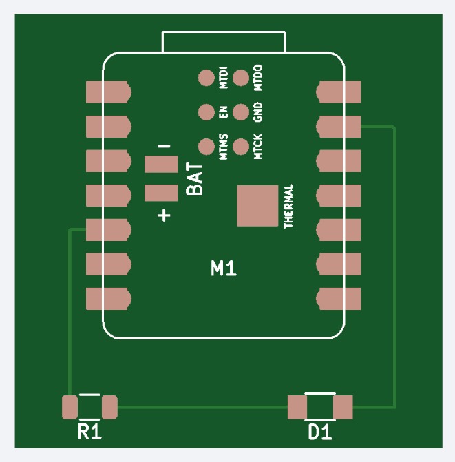
This is how the PCB shows up after being uploaded to JLCPCB.
Reflection
The circuits I created this week were very simple. Learning the basics of using microcontrollers and designing PCBs was an important early step toward creating more complex circuit designs later on. I'm a beginner when it comes to electronics, so this week's work with microcontrollers was definitely fruitful.
Between this week and next, I want to work on creating a more complex circuit design to interface with the ESP32 microcontroller. I came across a past assignment where a more advanced PCB was designed with enhanced functionality:
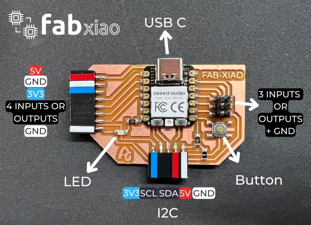
Past assignment example of a more advanced PCB design.
My goal is to create and mill a circuit board similar to this, which would enable much more functionality from the ESP32 than the simple board I designed.


