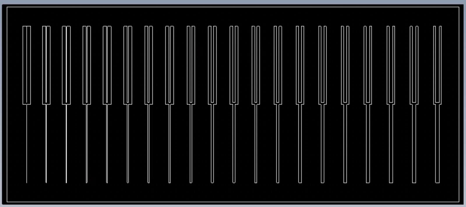
This week my group and I (David, Sara, Anthony) started by trying to test out the design rules and limitations for our electronics mill (Roland SRM-20). We designed the following image in Fusion. The width of the bottom rectangles and top cut outs ranges from 0.001 to 0.020 by increments of 0.001.
We found ourselves short on time so our focus shifted from testing out design rules to trying to mill functional boards. The board I wanted to mill was one I had been working on earlier in the week for my senior thesis. It's a pretty simple design using the Seeed Studio XIAO ESP32C3 microcontroller to actuate a solenoid valve with a MOSFET. This is important for my senior thesis project because it allows us to pass VOCs to sensor elements in periodic bursts. The lab I'm working in demonstrated that you can more easily distinguish between VOCs in a mixture of gasses when you pass the gas in periodic bursts in their paper "Nonequilibrium sensing of volatile compounds using active and passive analyte delivery."
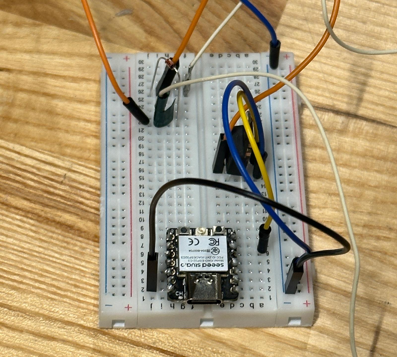
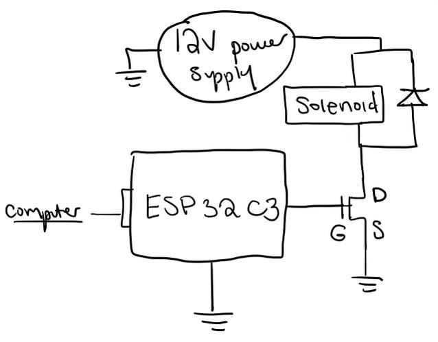
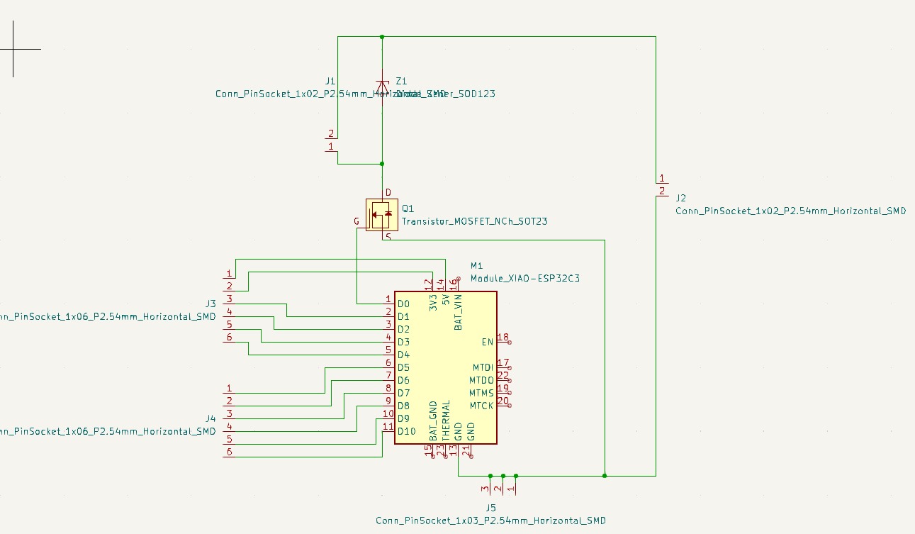
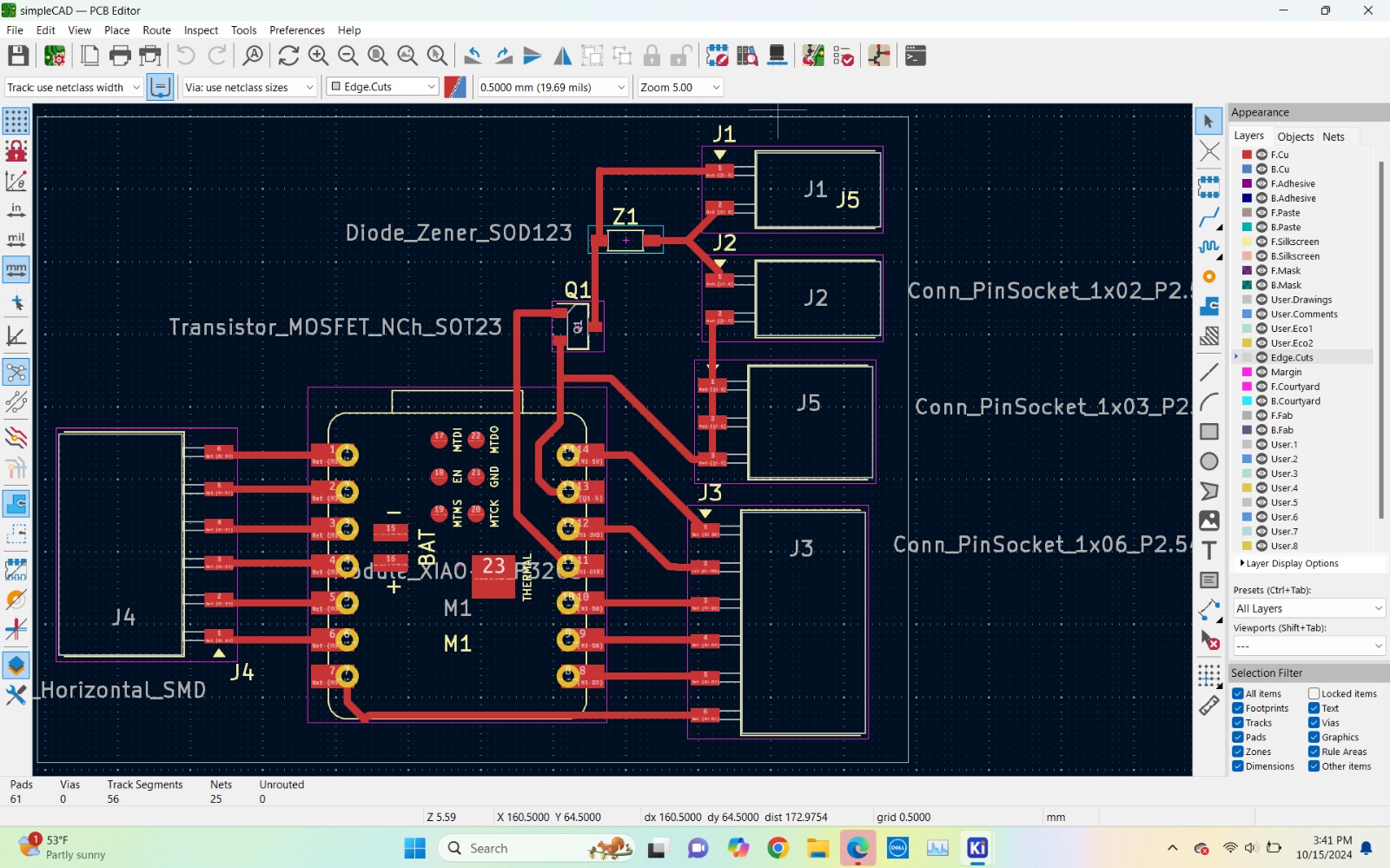
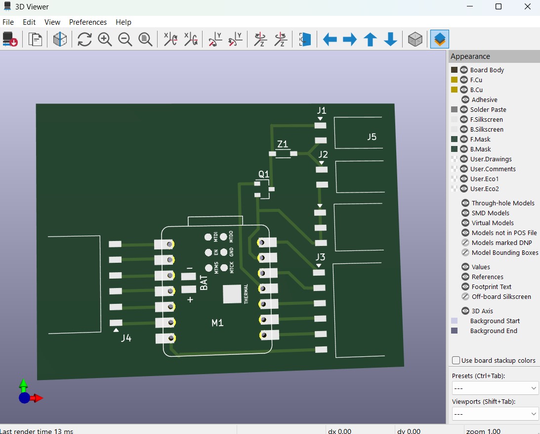
I started designing this board in KiCad so I could eventually mill it. It was a pretty simple design and it only used 2 pins of the microcontroller. I felt like this wasn't optimal, so I added a bunch of female header connectors so I could plug into the rest of the pins of the microcontroller. Below is the schematic design and the PCB design in the KiCad software.
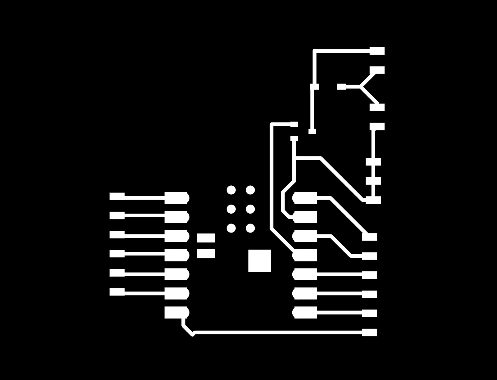
I turned my board into an SVG then a png. I used the mods tool to then mill my board. Note: Leo was extremely helpful here. He had a very useful guide on how to use this with the mill. He was also extremely helpful in troubleshooting an issue we had with the mill. It seemed only to be working with Macs.
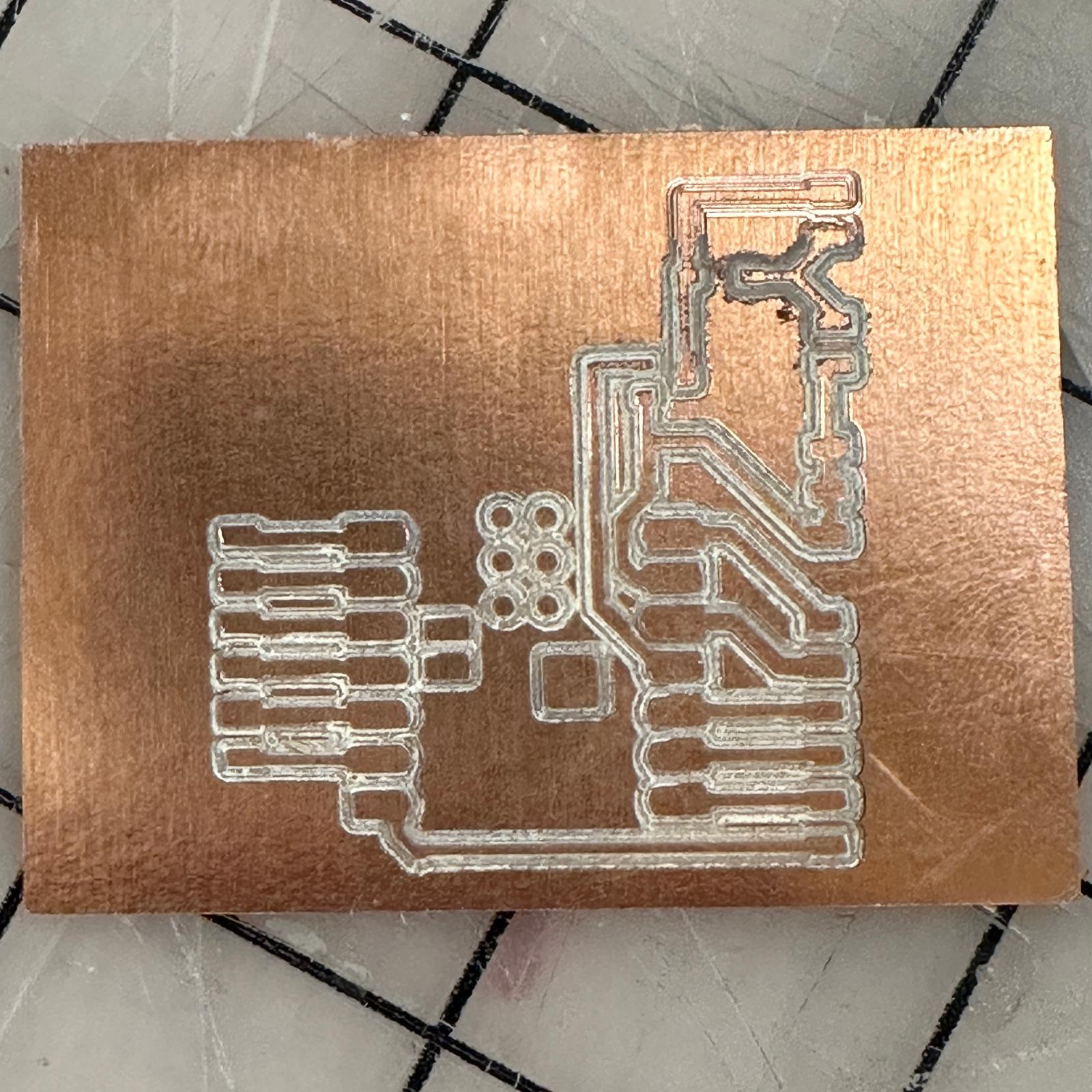
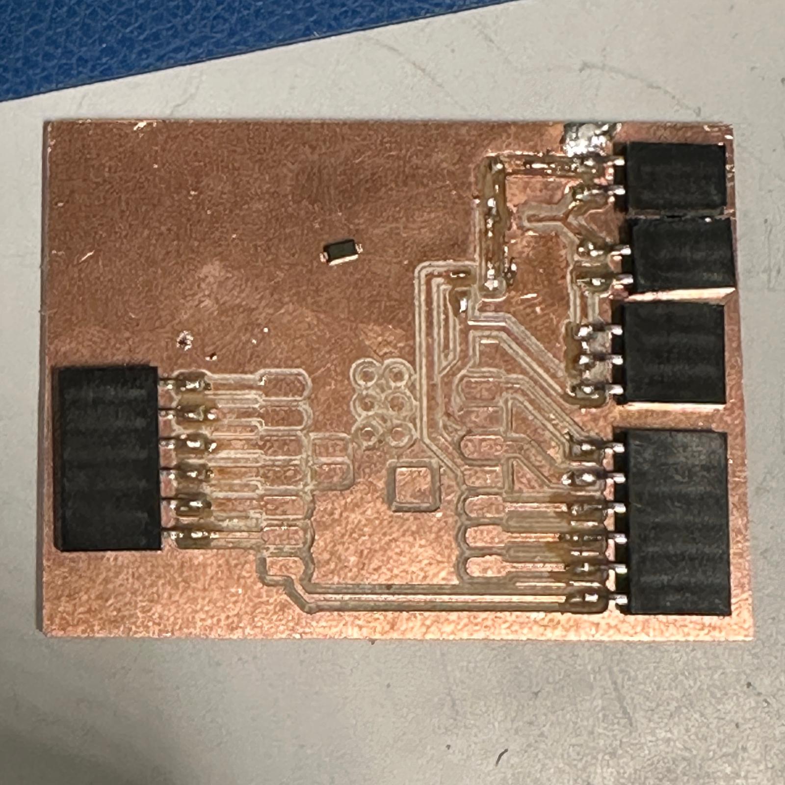
The mill started working and my board came out well! Sort of. It didn't fully cut through at certain points so I went back in with an exacto knife to clear out some extra copper. All seemed to be going well until my hand slipped and I accidentally sliced a copper wire that I needed! Oops. Whatever.
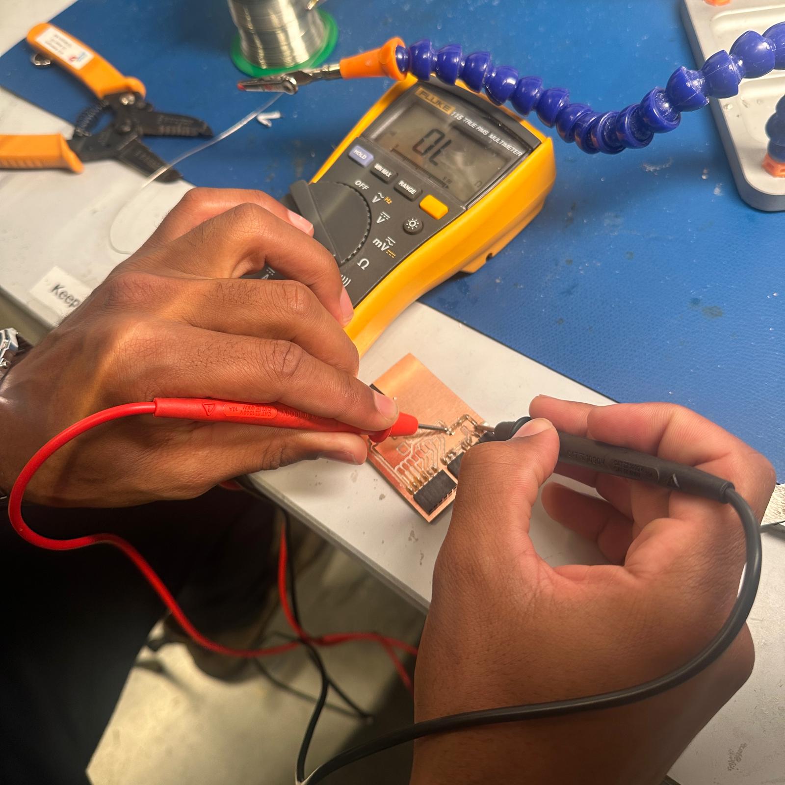
I continued by soldering on my female headers which went very well! I planned to repair my earlier error this by soldering on a wire connecting the two parts but that proved very difficult and I made the problem way worse. Whatever. Testing with a breadboard confirmed that I had fully botched my board. I continued to try to Frankenstein it back together but when I started burning my fingers with the soldering iron in a desperate attempt to get it to work I figured it was time to call it quits.
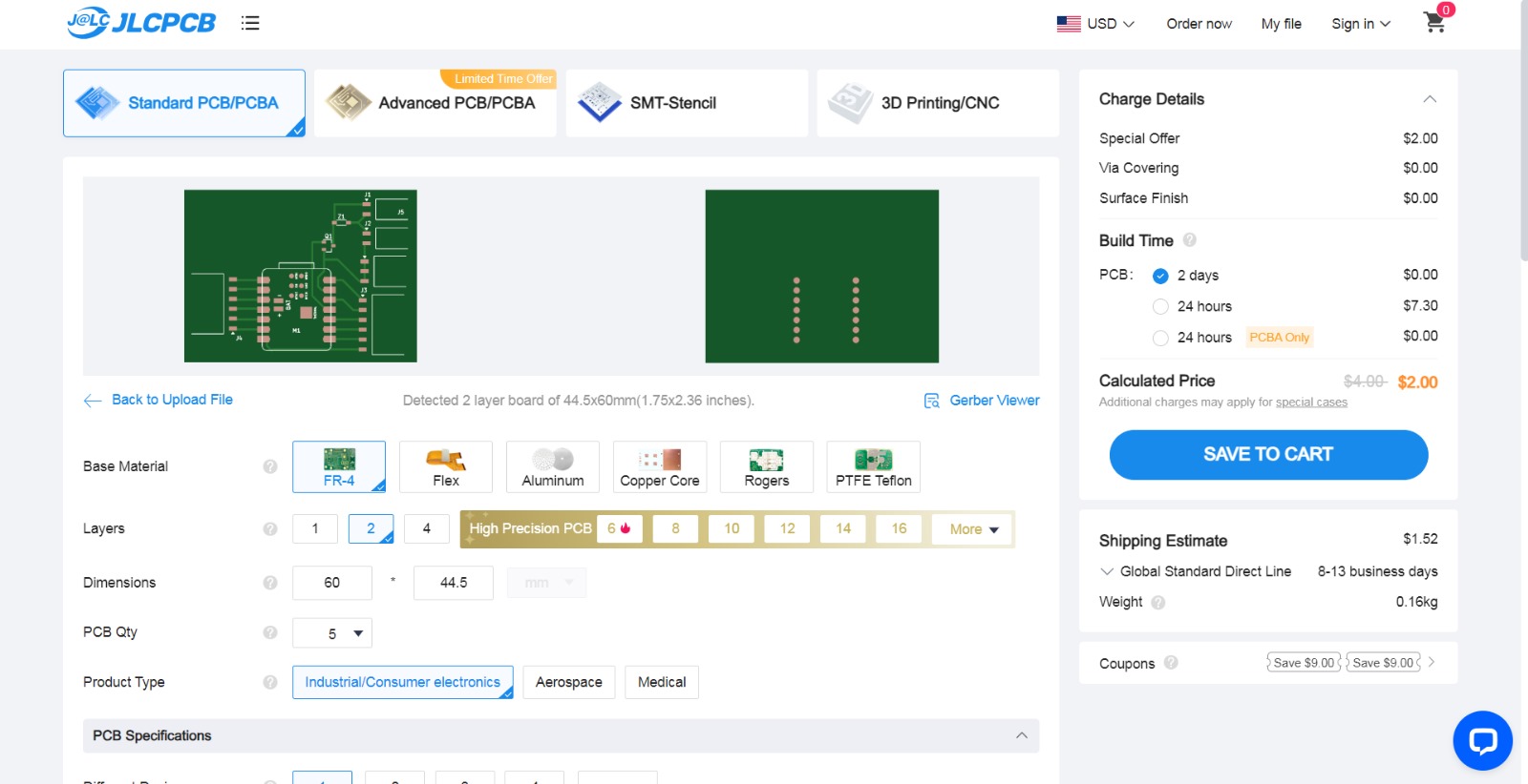
All is not lost. Earlier, I had uploaded my board design as gerber files to JCLPCB, and ordered 5 of the same board. The board and shipping together cost me only $3.74. I will try again to solder my components on once the boards arrive.
This week was a learning experience for certain. I got better at using KiCad and I improved on my garbage electronics design from last week. (Last week I literally just made a circuit to light up an LED.) I also became familiar with the mill, which could be useful. After struggling with my milled PCB for a while though, I learned that buying PCBs online is very very cheap and probably much easier than milling them myself. Thanks again to Leo for the help with the mill.