Group Project
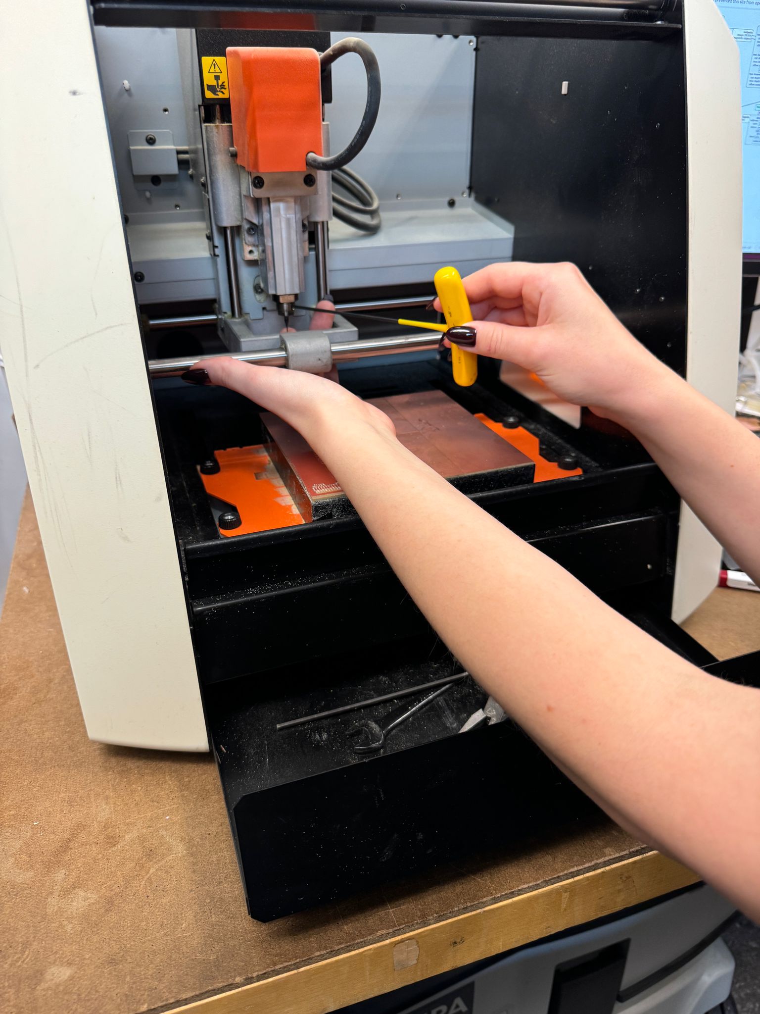
This week was a roller coaster! As I've mentioned in the past, electronics are super new to me. Electrical engineering has always been like a black box (filled with vipers), so the idea of materializing a working PCB was daunting. Thankfully, the group project and training were helpful in getting things going. We learned how to convert gerber files to pngs and then upload them to the mods for board milling.
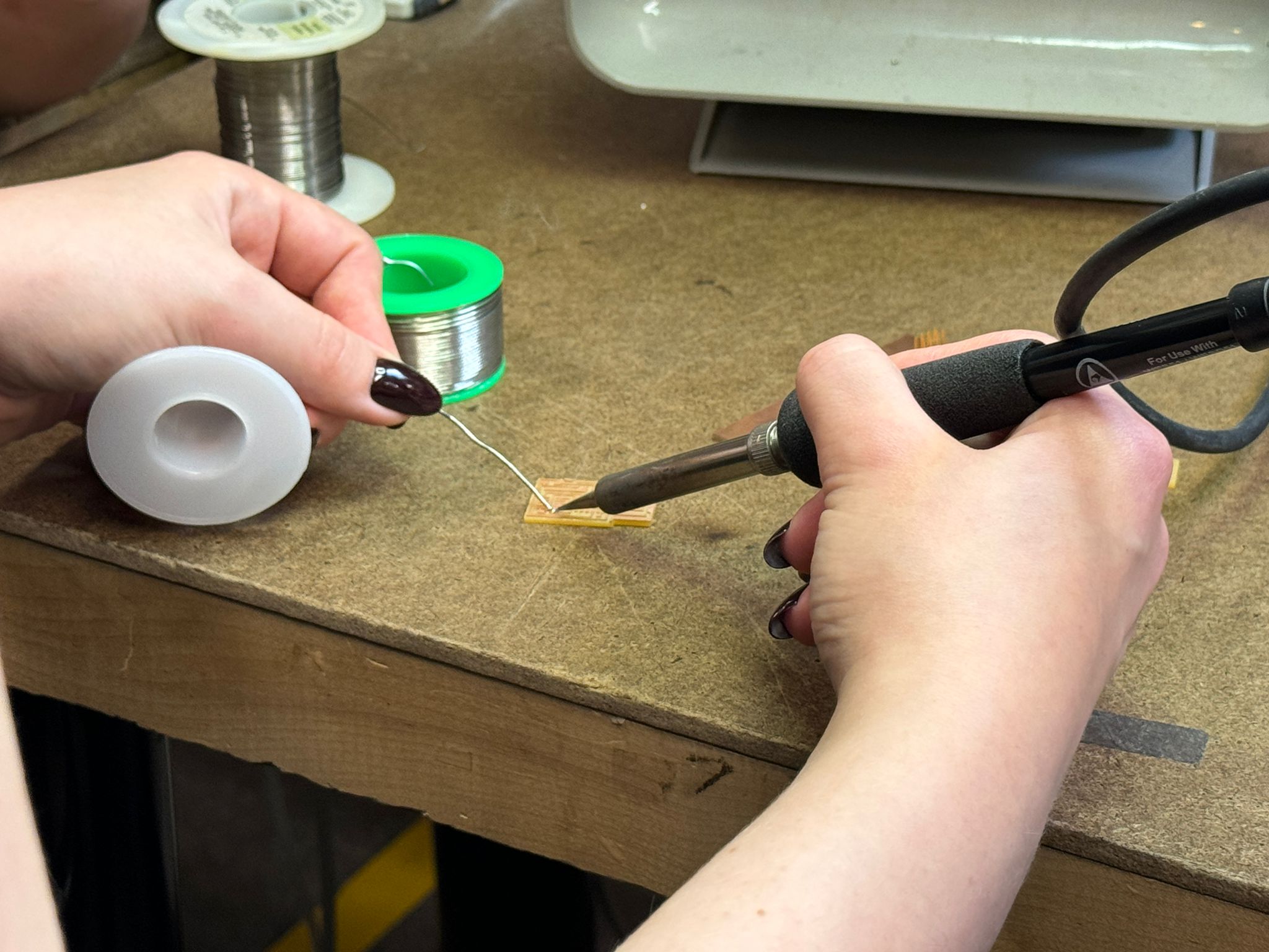
After milling our boards, we learned to develop a workflow for gathering our components, orienting them properly, and carefully soldering them to our freshly milled board.
Electronic Production
I cannot stress this enough: I am at Baby's First PCB level here. As helpful as the group work was, I still had trouble getting this week's individual assignment done; TA help was essential and extremely helpful throughout this process, and I owe the work I have here to them. Every time I say "I" here, note that it should actually be more like "we."
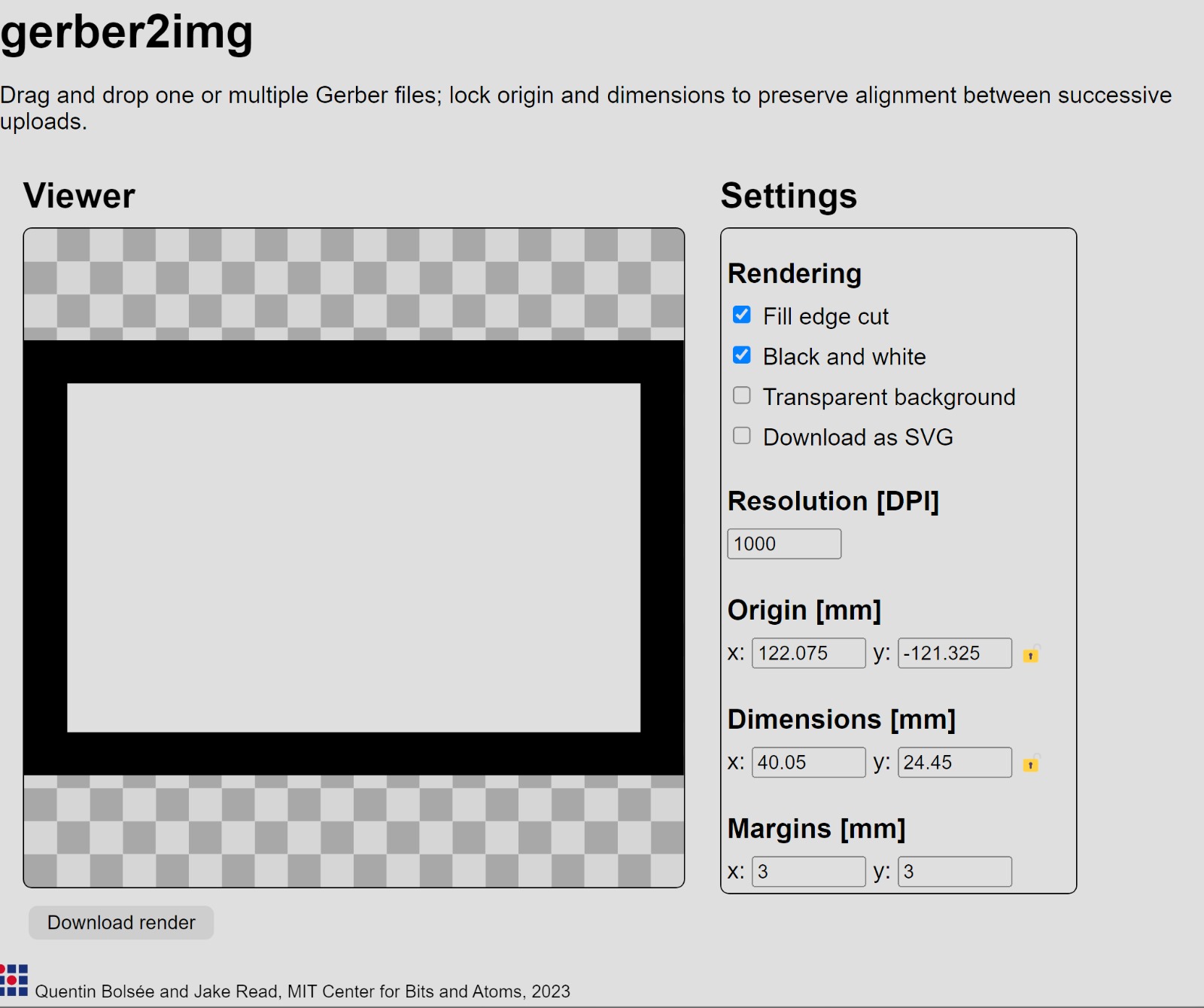
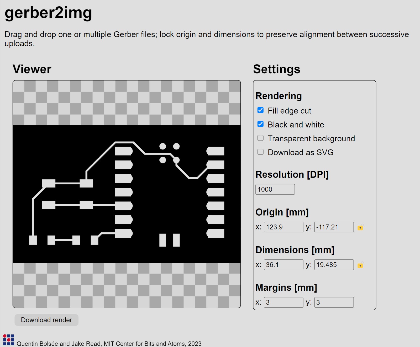
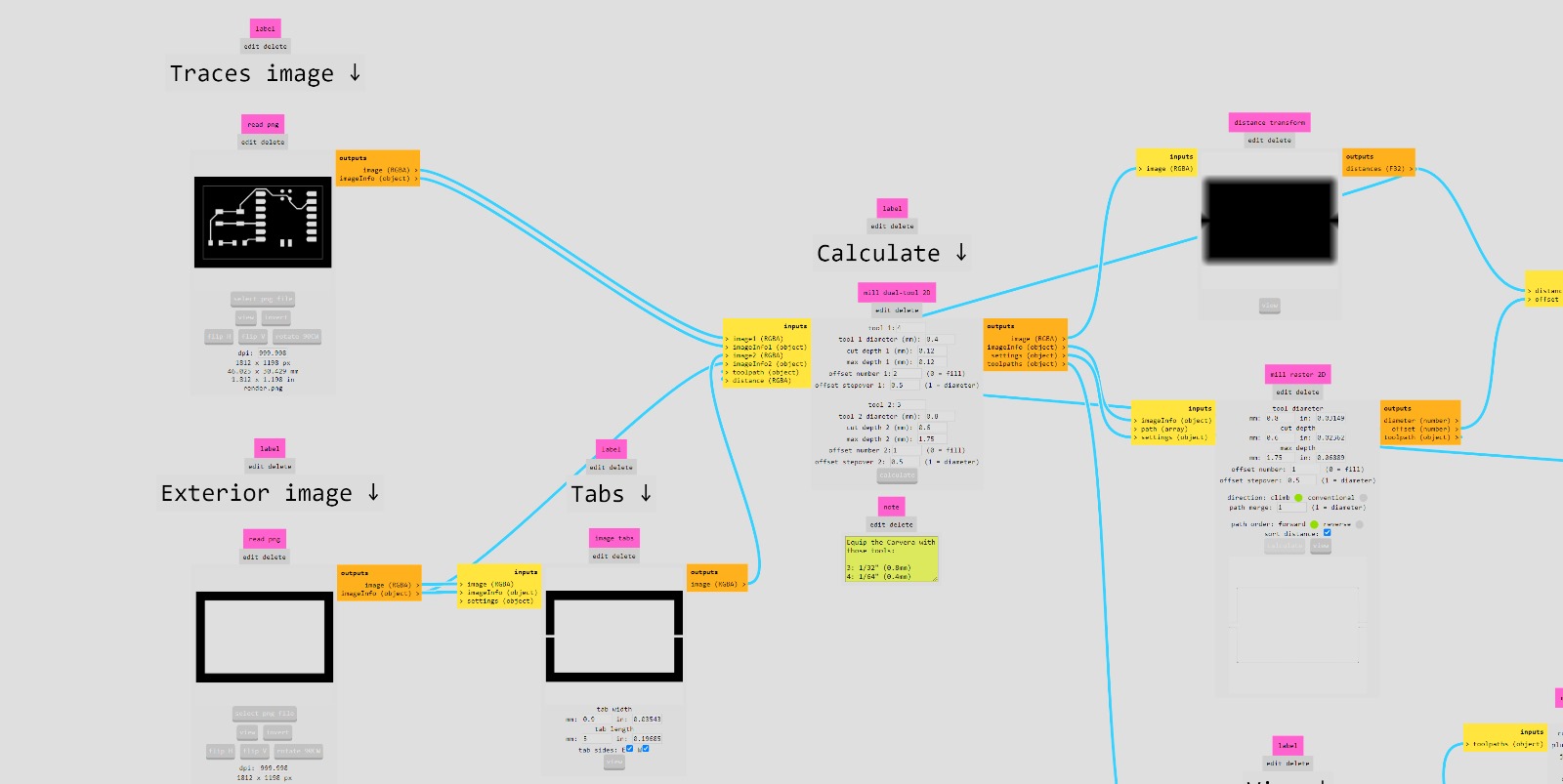
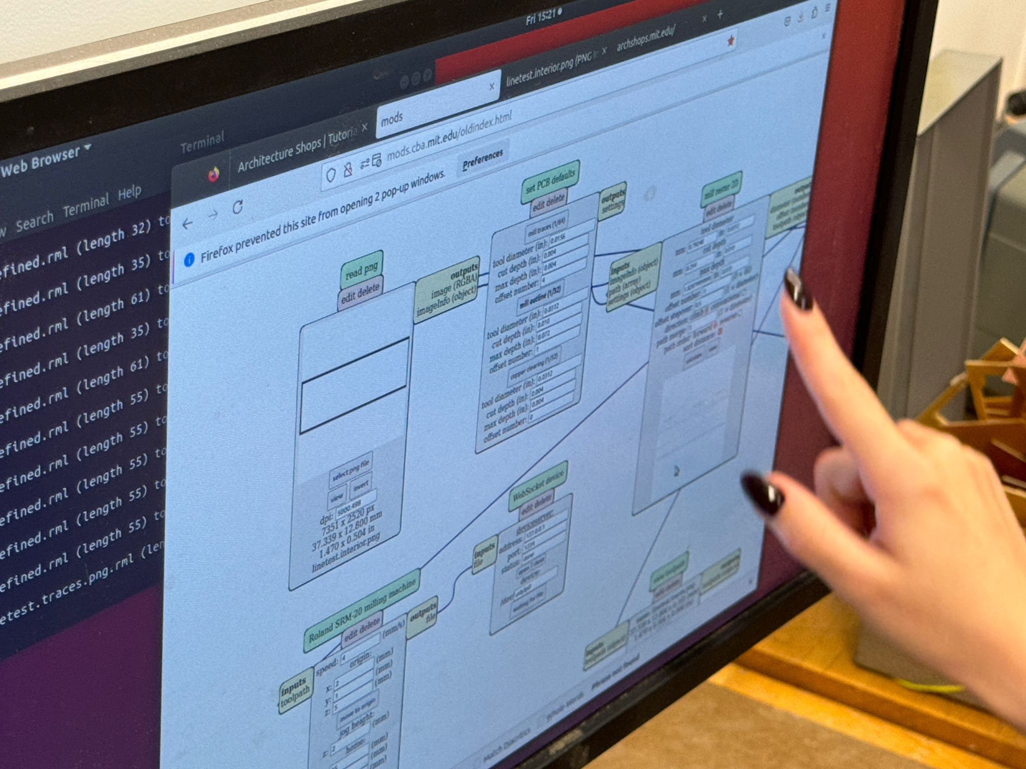
I started things off by exporting the simple board I designed last week as a gerber file and then converting it to pngs to then be uploaded to mods.
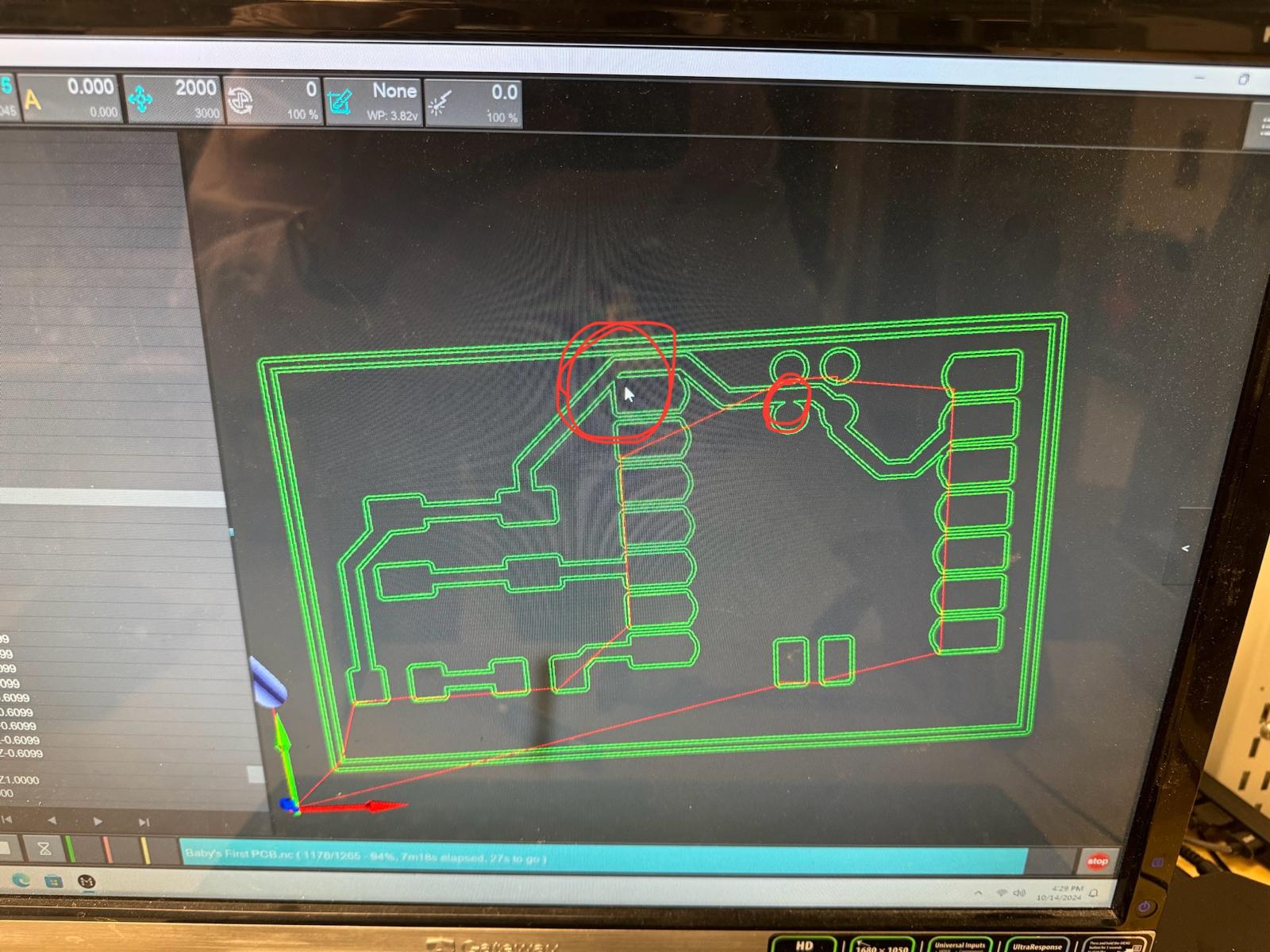
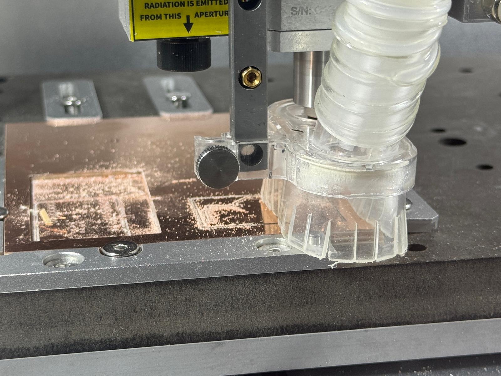
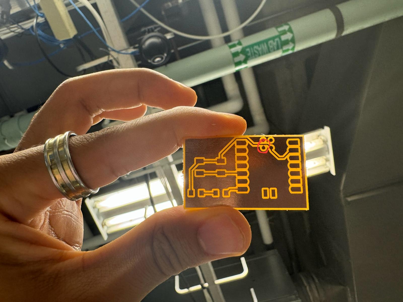
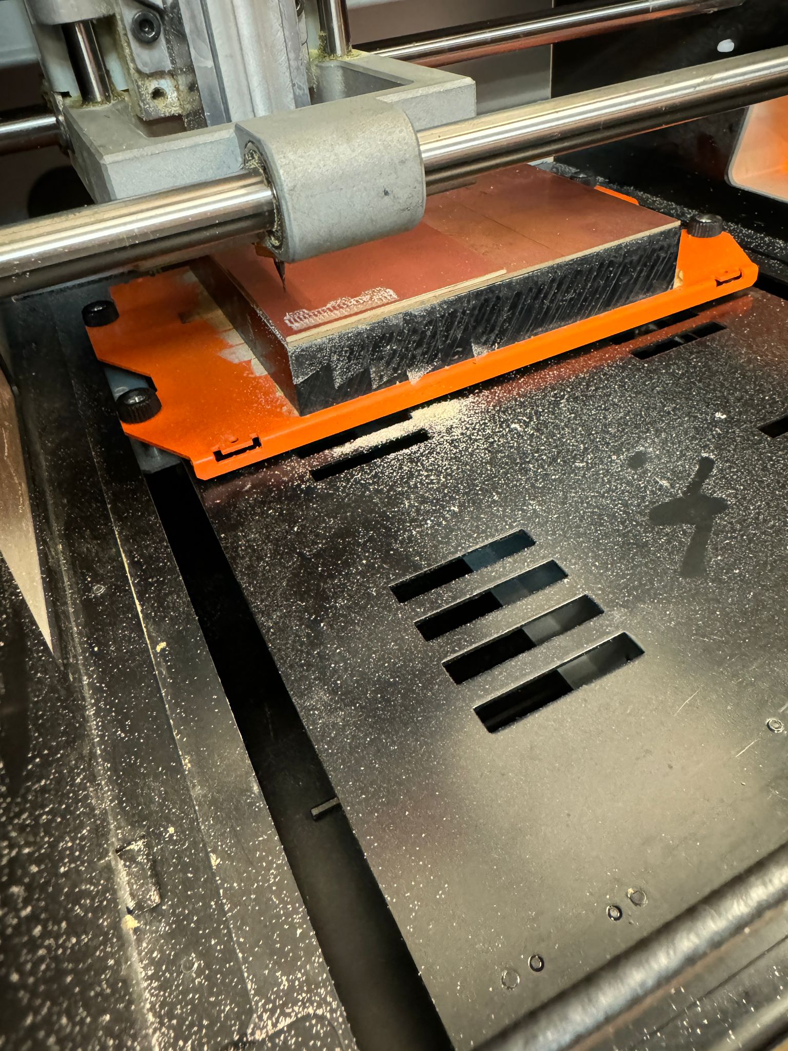
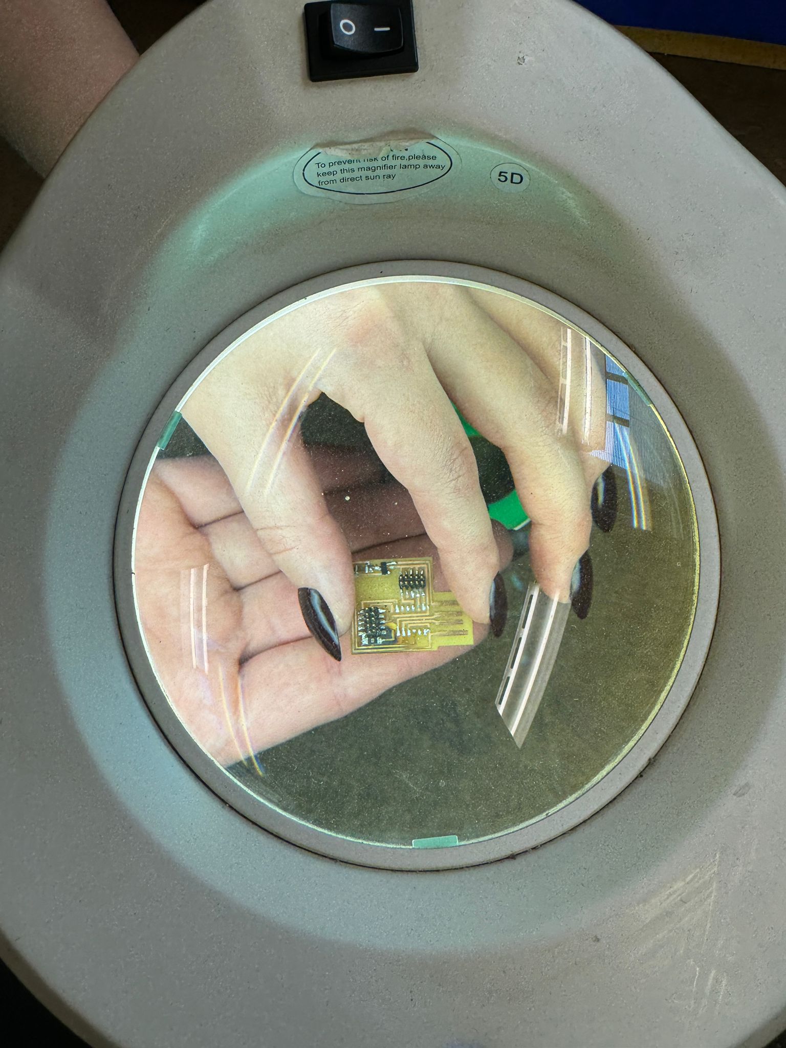
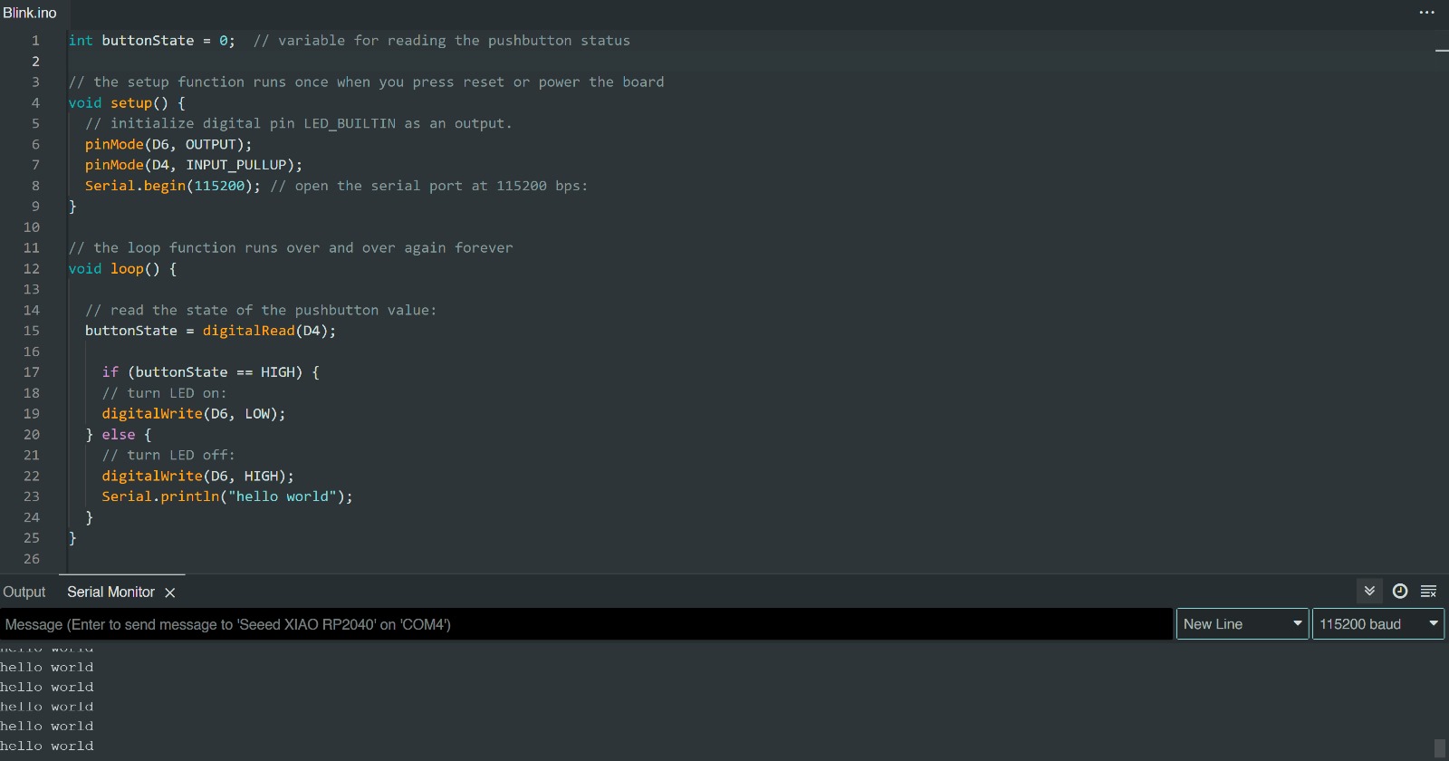
Then I milled my board! This went off (almost) without a hitch. A look at the monitor I was milling from showed that I might have a couple overlapping traces (circled in red) that I would likely have to cut out gaps for by hand. Holding the freshly milled board up to the light indicated that there was just one case where this happened; a quick slash from a box cutter removed this thin copper bridge.
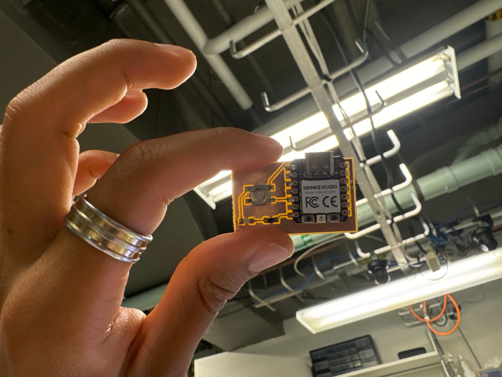
Soldering the board took longer than expected and a lot of trial and error but eventually I got my components placed down. Several tests with the multimeter helped me confirm that everything was connected properly. Now it was time to open up the Arduino IDE, hook up my RP2040 to my computer, and start running some code.
Just to make sure my microcontroller could actually respond to the computer, I started things off with a very simple blink test, the code for which was already publicly available on the Arduino IDE. This worked! Watch the little light in the top right blink every second in the video above.
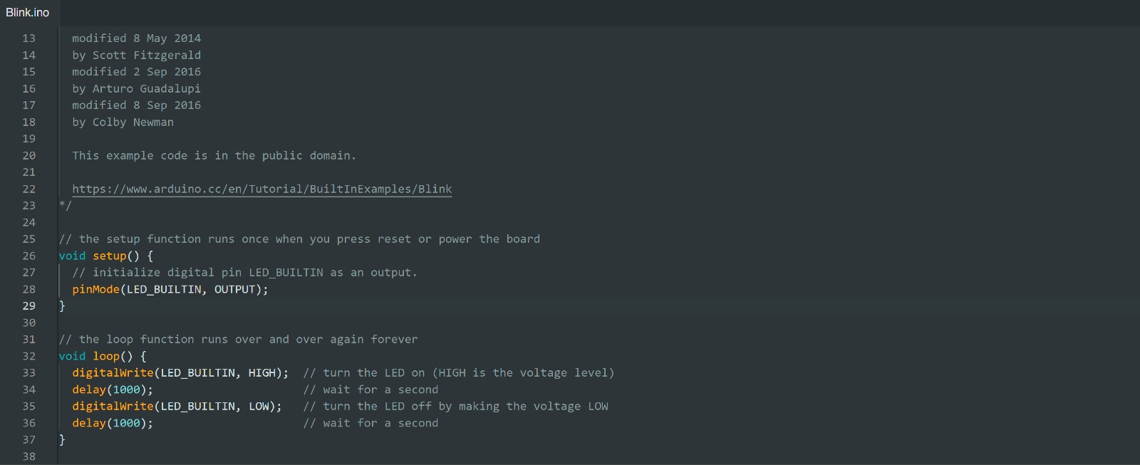
Now to start testing the components themselves. I made a very simple modification to the blink code, setting things so that the LED I had soldered to my board would blink instead. This also worked (see above)! So far so good.
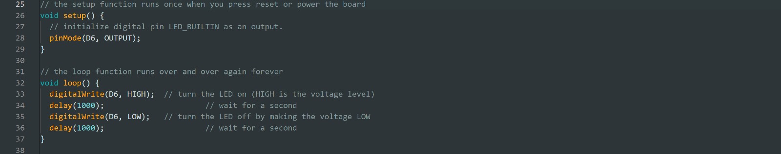
Now for the final test of my board's functionality: I added additional code so that pressing and holding my button would turn on my LED, and releasing the button would turn it back off. This also worked! Yay! I also tried to get the microcontroller to print a message whenever I turned a light on, but it kept looping and sending the message infinitely. Whoops!
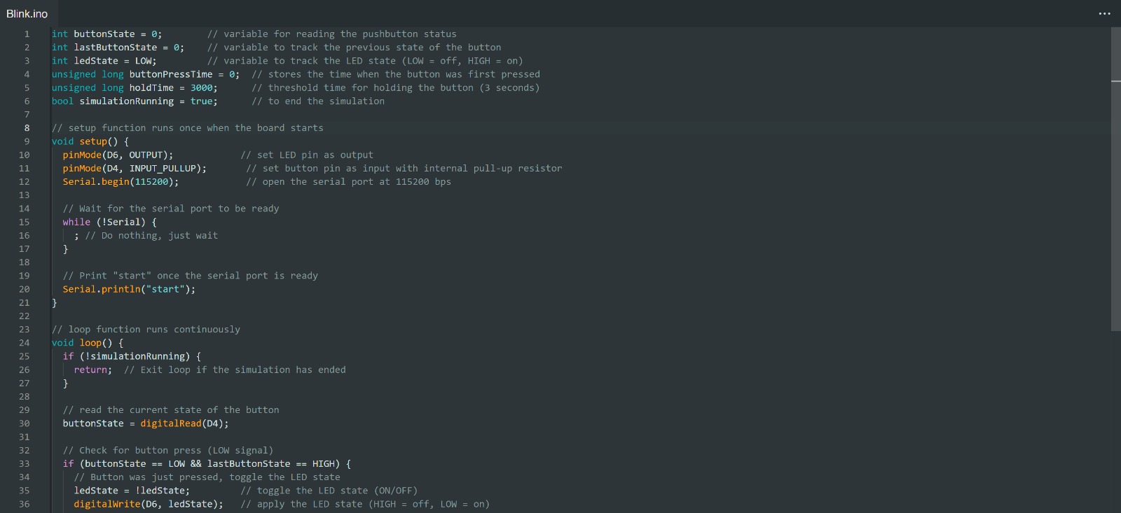
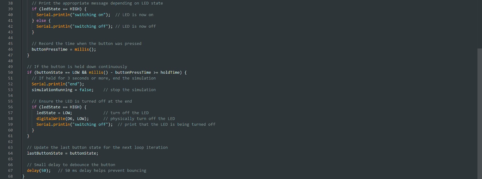
To cap the week off, I tried to take my code one step further. With some help from ChatGPT, I rewrote the code to do several things: first, simply pushing the button would toggle the light, rather than having to hold it; second, holding the button for three seconds would turn off the light if it's on and end the simulation; third, the microcontroller would print updates to the simulation based on actions undertaken ("start", "switching on", "switching off", and "end"). This took some time and some debugging but eventually this worked too! Baby's first PCB complete! This was a daunting task for me, even for a simple board, and I'm proud of what I've done here. Looking forward to a future of more complicated electronics!