Group Project
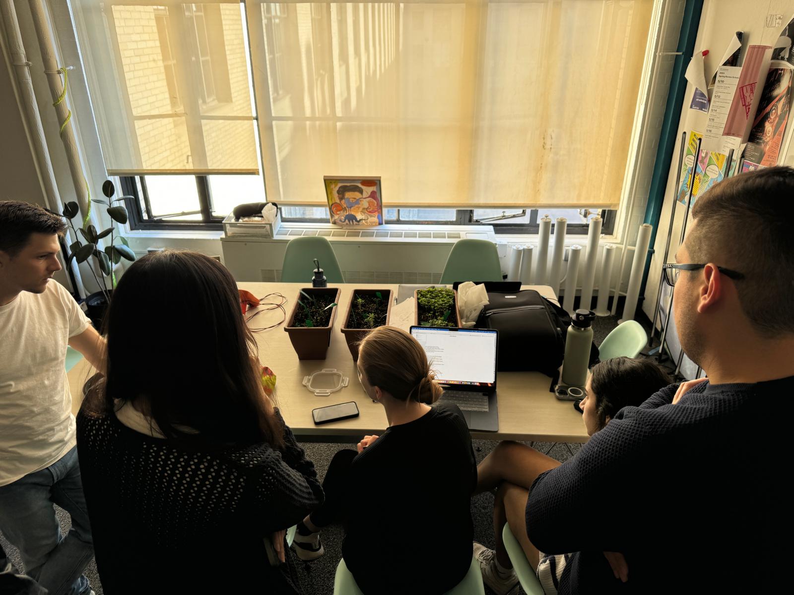
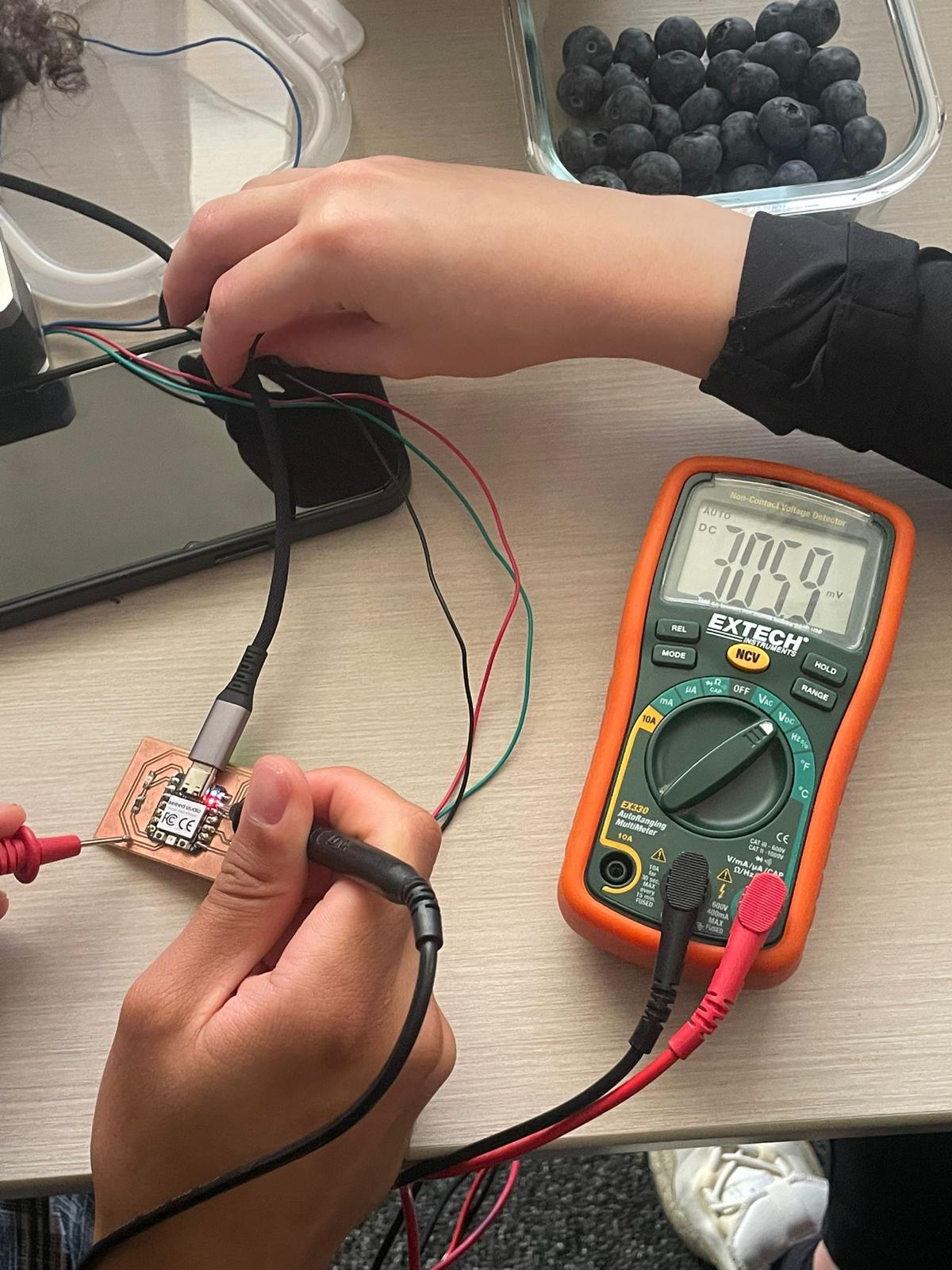
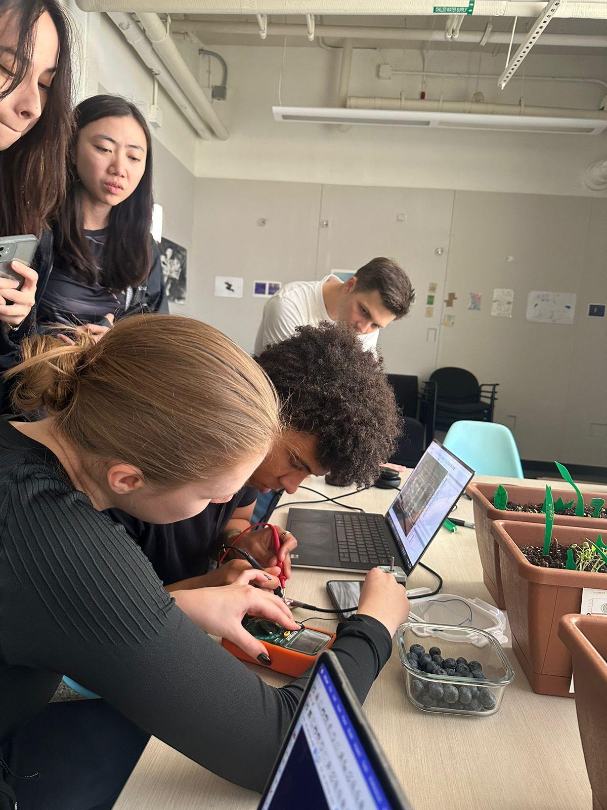
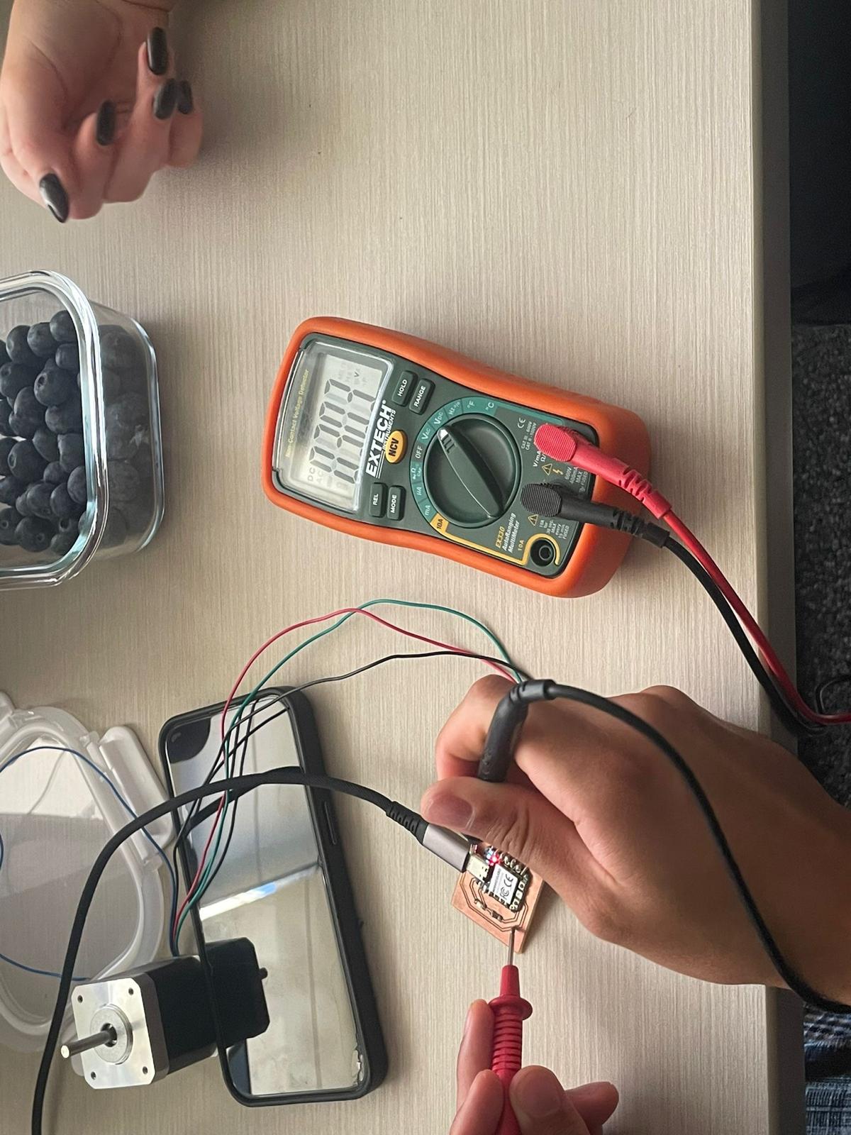
Our TA, Diana, was out sick this week, so we unfortunately didn't get the opportunity to meet as a group and probe an input device's analog levels and digital signals. Will find time to do this in the future!
Alex from the future here delivering findings from group assignment as promised:
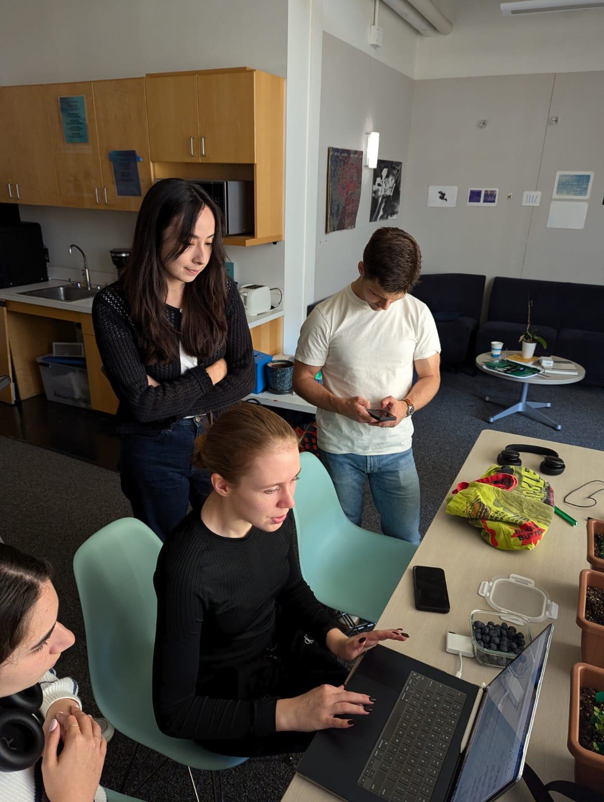
Input Devices
I wanted to take this assignment as an opportunity to push my final project further. I already have a large chunk of the physical mechanism worked out, but now I have to start thinking about the electronics side of things. My lotus lamp needs to be able to detect the level of light and, based on that level of light, decide whether the lamp should be closed or open.
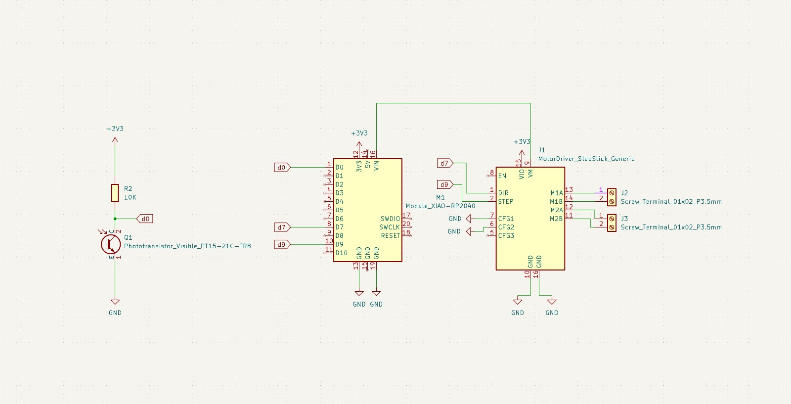
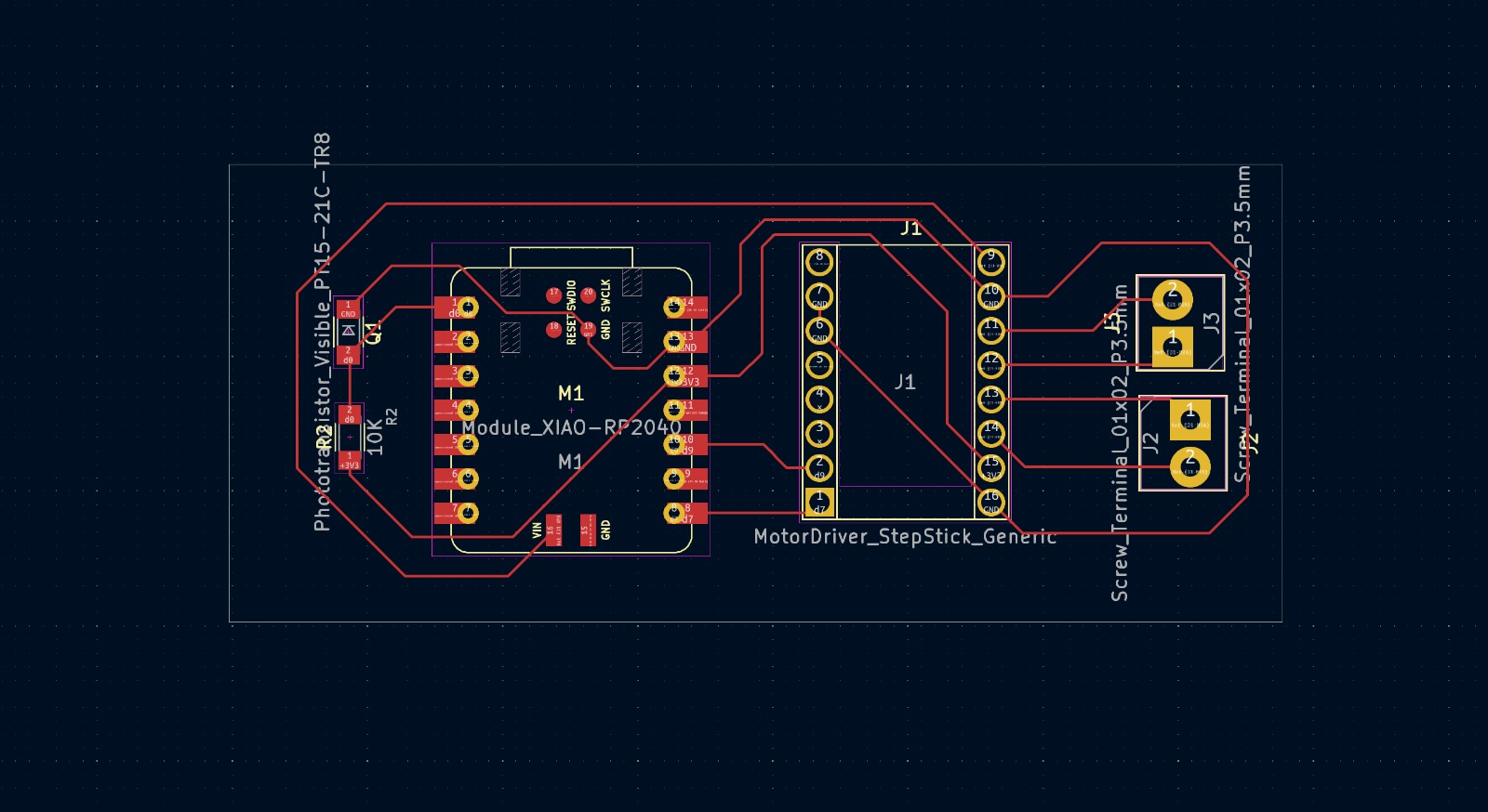
And so begins the first week of what will be a two week project. With tremendous amazing incredible showstopping help from Quentin, Jake, and Eric, I jumped into KiCad and designed a "simple" board that would hopefully pass information on the light level from a phototransistor to an RP2040, which would in turn pass information to a stepper motor driver, which would finally direct a stepper motor to rotate in increments of 180 degrees. For this week, though, I'm only focused on the communication between my phototransistor and my RP2040.
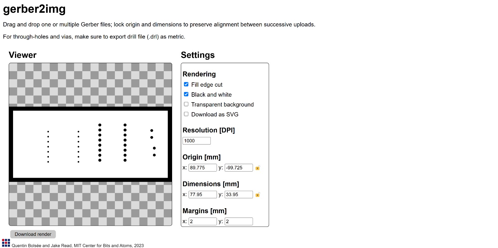
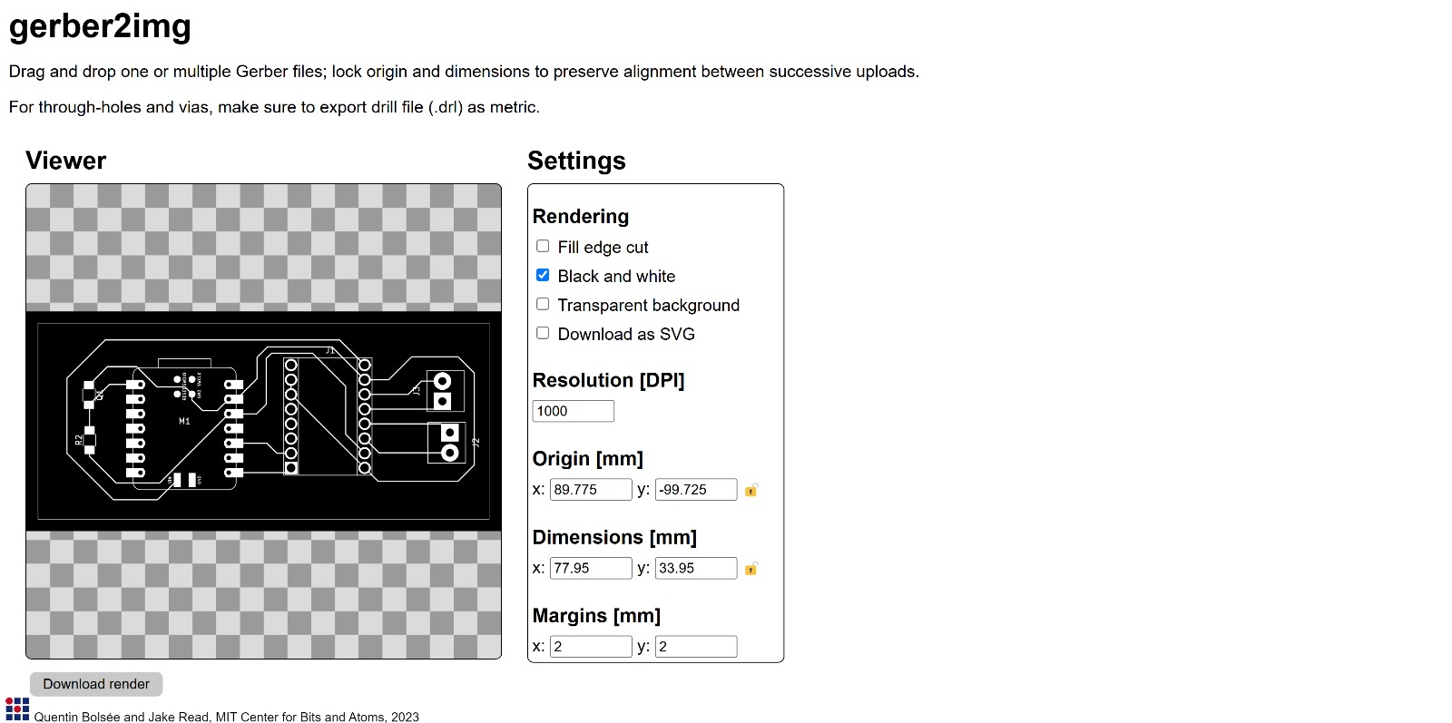
I ran into a couple hiccups as I tried to set up my board for milling. First, I had some issues with exporting my KiCad file into appropriate drill and gerber files, and then bringing those files into gerber2img. I wasn't sure which layers to include or not include (I would eventually find out I only need the front copper and edge cuts layers) or how to differentiate between through holes and pads. Eventually I decided to simply export with all through holes, use gerber2img to make my png files, and then photoshop the png files to cover up where the holes should actually be pads.
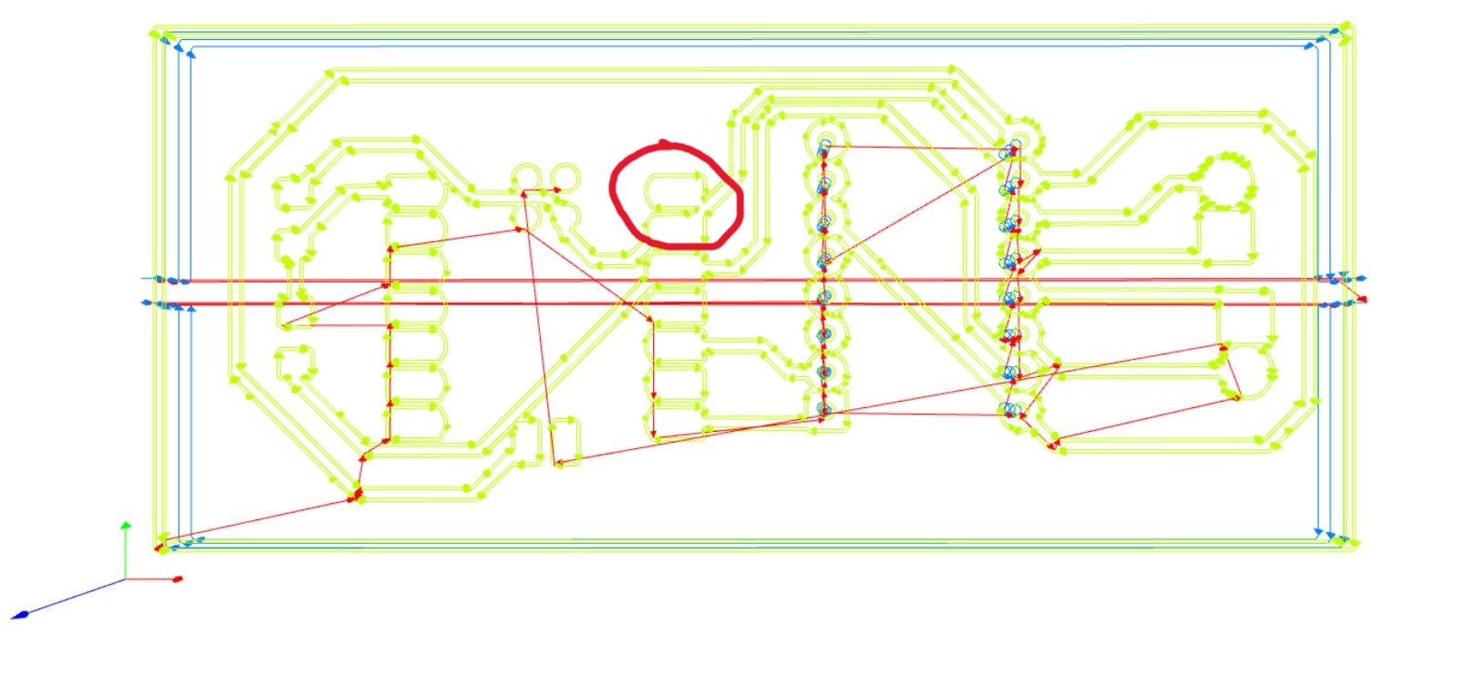
The second major hiccup came when I was all the way in mods and about to mill. The mill preview showed me that I had forgotten to set up design rules in KiCad and made some traces and pads too close to each other. So that set me back a bit. But here's a montage of some things going right:
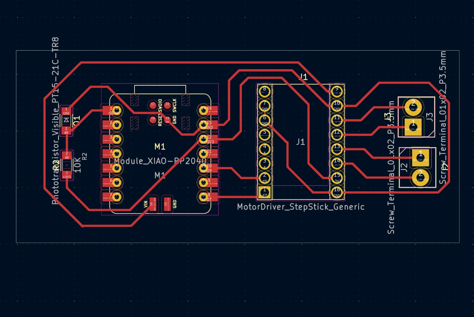
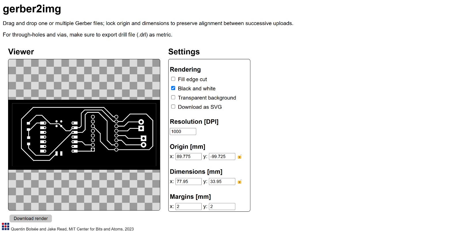
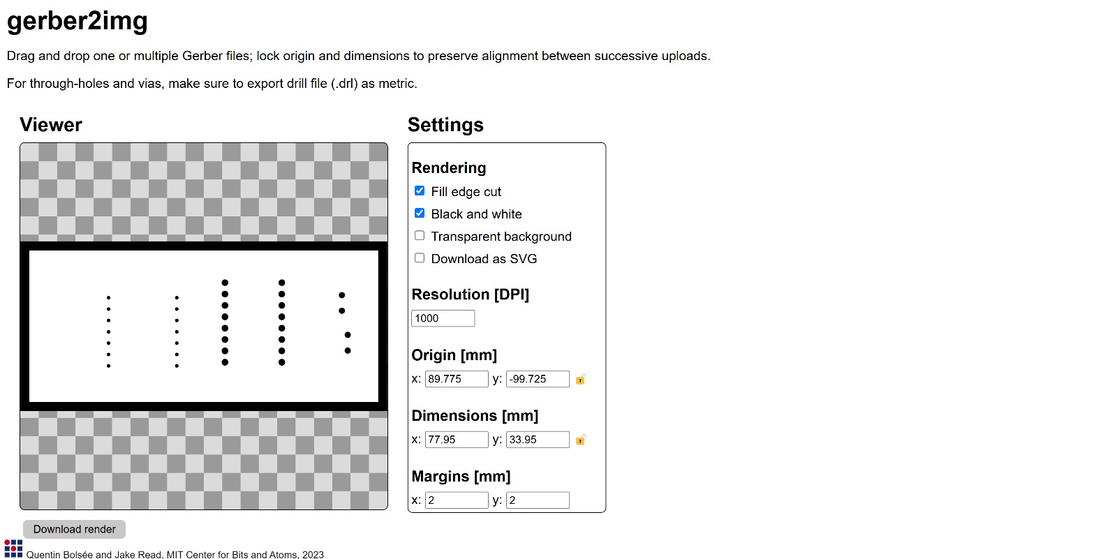
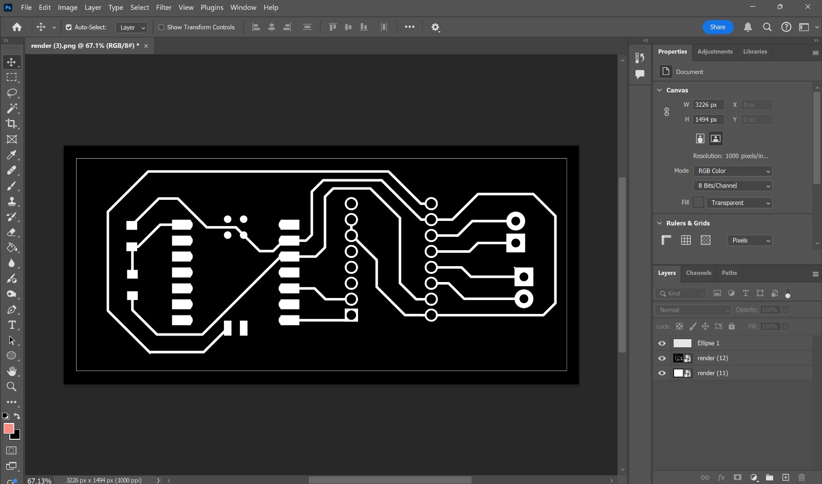
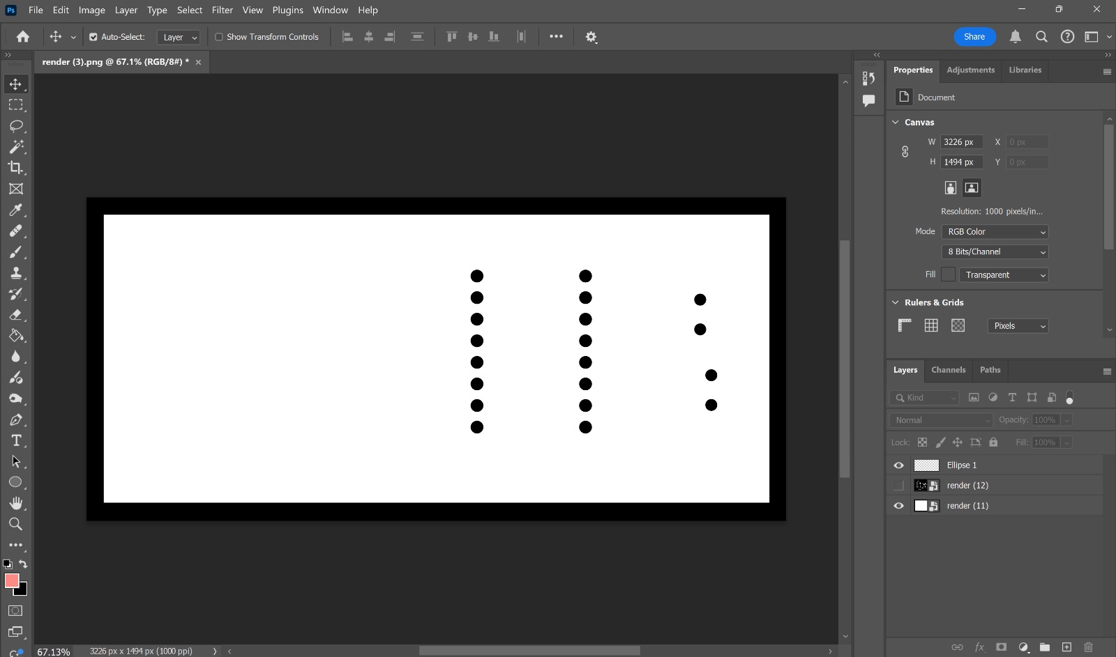
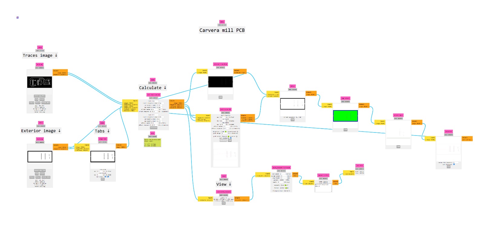
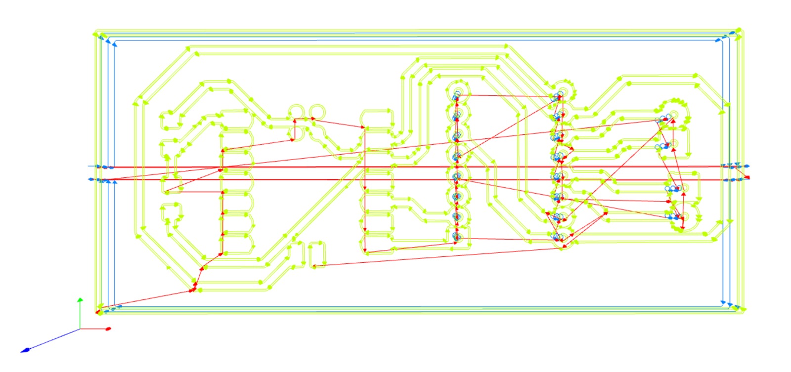
Now for the milling, which I did with the fancy Carvera in CBA with help from Kyle:
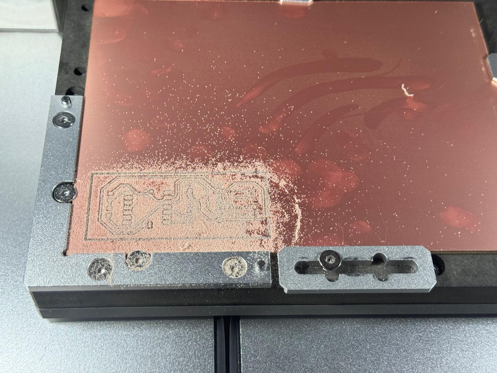
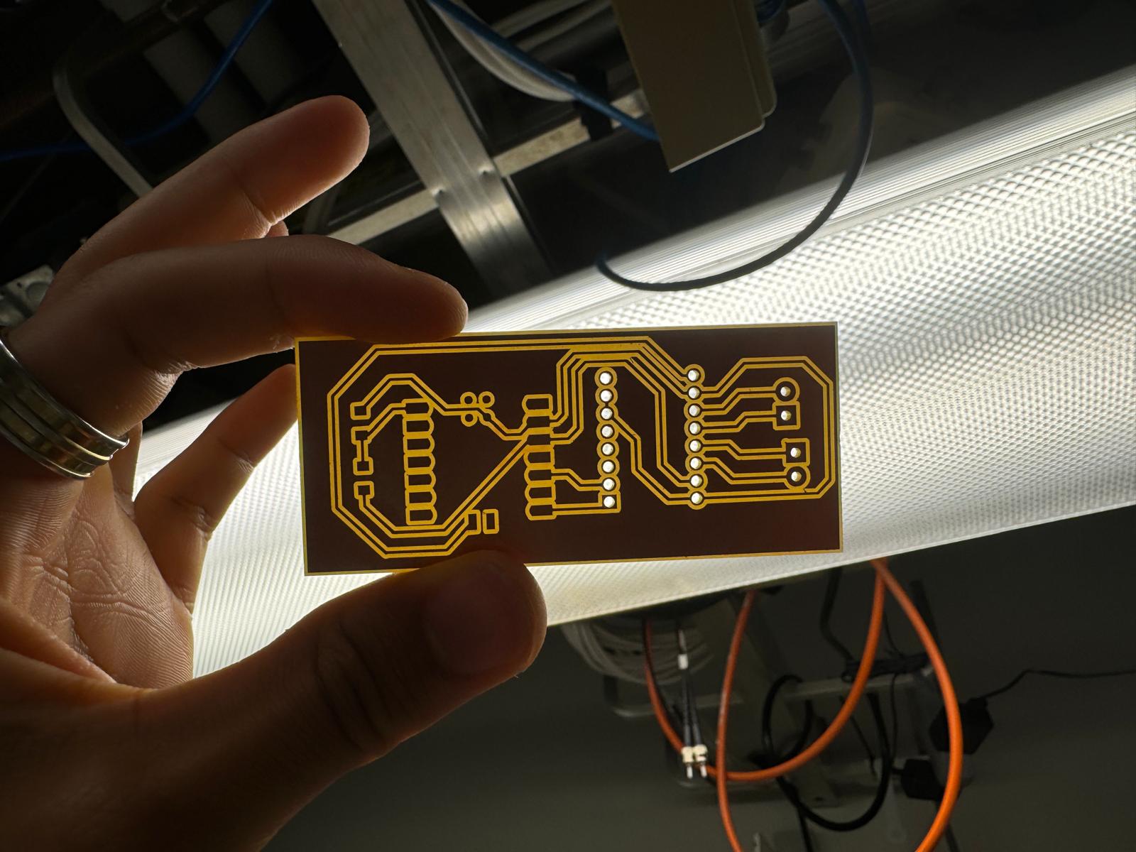
Got it on the first try! Collecting the components I needed was more difficult than expected (it was especially hard to find 3.5 mm screw terminals; will design for 0.1" screw terminals in the future), and soldering was about as difficult as expected. But eventually, that got done too:
Now, with some serious supportive heavylifting from ChatGPT, it was time to code my RP2040 to read and report on my phototransistor. I started by setting a simple code to do just that, which worked:
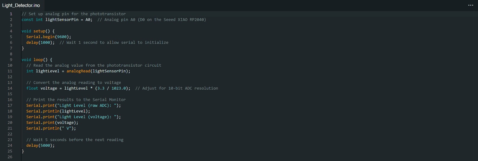
My RP2040 was able to accurately report on the phototransistor's light level, both in raw ADC and voltage. I found the raw ADC to be the most helpful statistic. The raw analog-to-digital converter reading is on a scale from 0 to 1023, with 0 corresponding to a ton of light and 1023 corresponding to the absence of light. After I got an understanding of what conditions caused what light level readings, I modified my code to tell me more information:
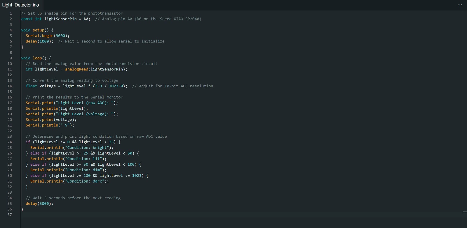
Now, the code will tell me in real time whether my board is under bright conditions, averagely lit conditions, dim conditions, or dark conditions.