Documentation
Episode 1 - Brainstorming
Okay I am slightly behind on this project so I am going to start by making the spiral plan There are a few things that I have to design in parallel.
Rough Design
I had my midterm review with my TA and it seems that I might not finish the whole idea of the Project on time so I am doing a simplification. For one making it all fit into something that resembles the size of the purse may be a littleeee too hard to do with the time limit that I have so I am basically simplifying it into an assembly that has the general shape of honey lemon's purse and has a container that drops onto another platform that then has paint mixed in it and delivered out. Before my meeting today with my TA I have to come up with a rough schematic sketch and a timeline. Woo I have two hours and a class that lasts an hour and a half before that so lets get cracking.
Subsystem Breakdown and Timeline
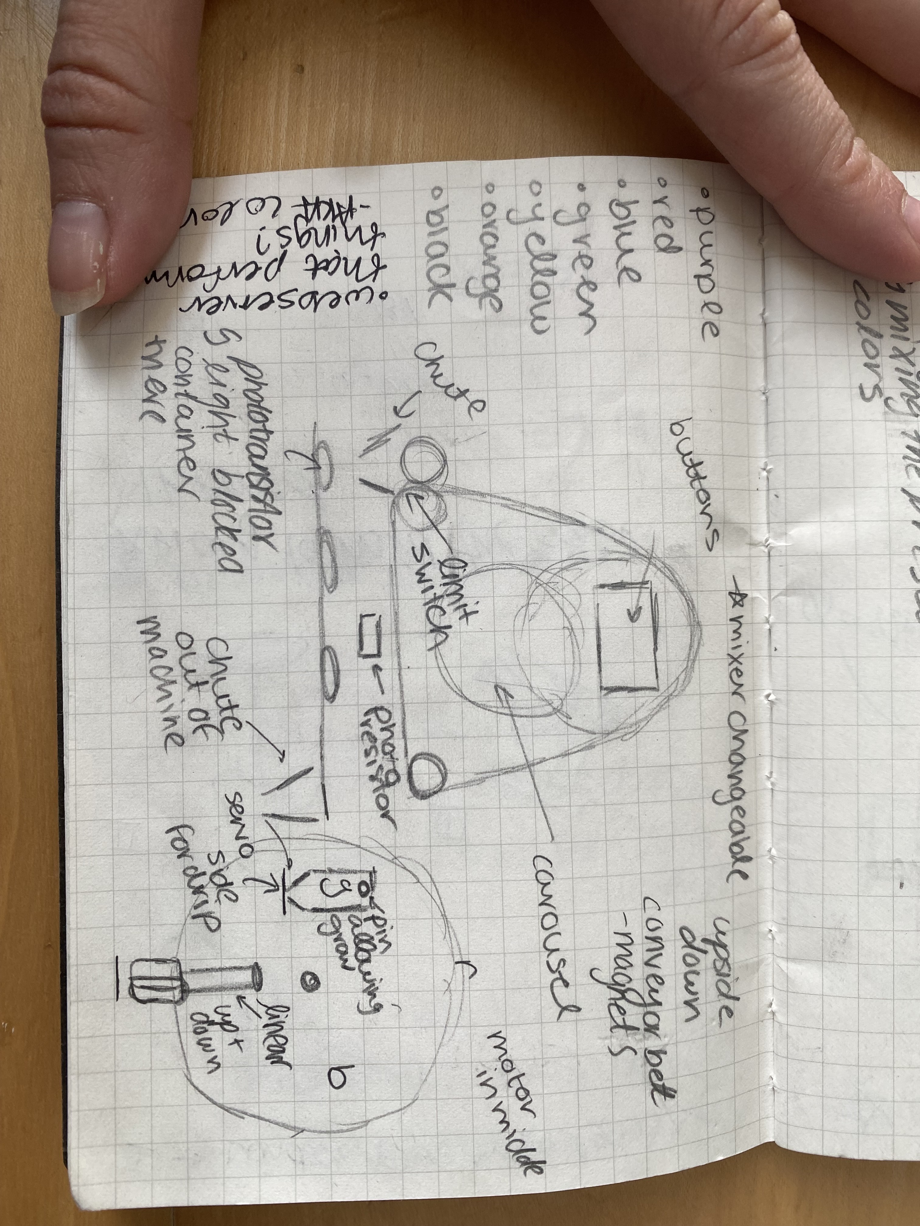
Subsystem 1 - the bigger conveyour belt that is the "strap" of the purse.
The idea
of this subsystem is that it has three circles that drive the belt around maybe connected together with pulleys
and belts. Each container will have a magnet that allows for it to connect to the conveyor belt. the container
will then hit a limit switch which will let the system know to turn off the electromagnet and it will fall down
a chute into the second subsystem
Subsystem 2 - the linear conveyour belt.
This is from the moment the container falls into it. There will be
some sort of touch sensor allowing the system to sense that the container has landed which puts into
play the rest of the machine and will start the conveyour belt. The conveyour belt will turn until it blocks
the phototransistor with the container and then it will stop and transition into subsystem 3. After it
finishes with subsystem 3 it will proceed to move again and drop the container down another chute
Subsystem 3 - carousel
The carousel has four main components including three drippers with colors red,green,blue, and a mixer.
The carousel will have five servos 1 per dripper and then one for a linear motion for the mixer and another
one for the rotational motion of the mixer. Then the entire carousel will be powered by a motor.
Subsystem 4 - Coding
I will have presets for different colors to be made and this involved a lot of testing to figure out the
right combination and amounts of colors.
So i have A LOT of work to do and this will be the breakdown of the timeline.
Week Nov 17-23: This week I will get the overall CAD done and also start on creating subsystem one. I will
also start the coding to make the system work
Week Nov 24-30: I will wrap up subsystem 1 and start working on susbsytem 2
Week Dec 1-7: I will wrap up subsystem 2 and start on subsystem 3 and integrate 1 and 2
Week Dec 8-14 Wrap up subsystem 4 and integrate 1,2, and 3
Week Dec 15-16: Final tweaking and integrating system 4
DECEMBER 17th - FINAL PRESENTATION
Subystem 1 - CAD
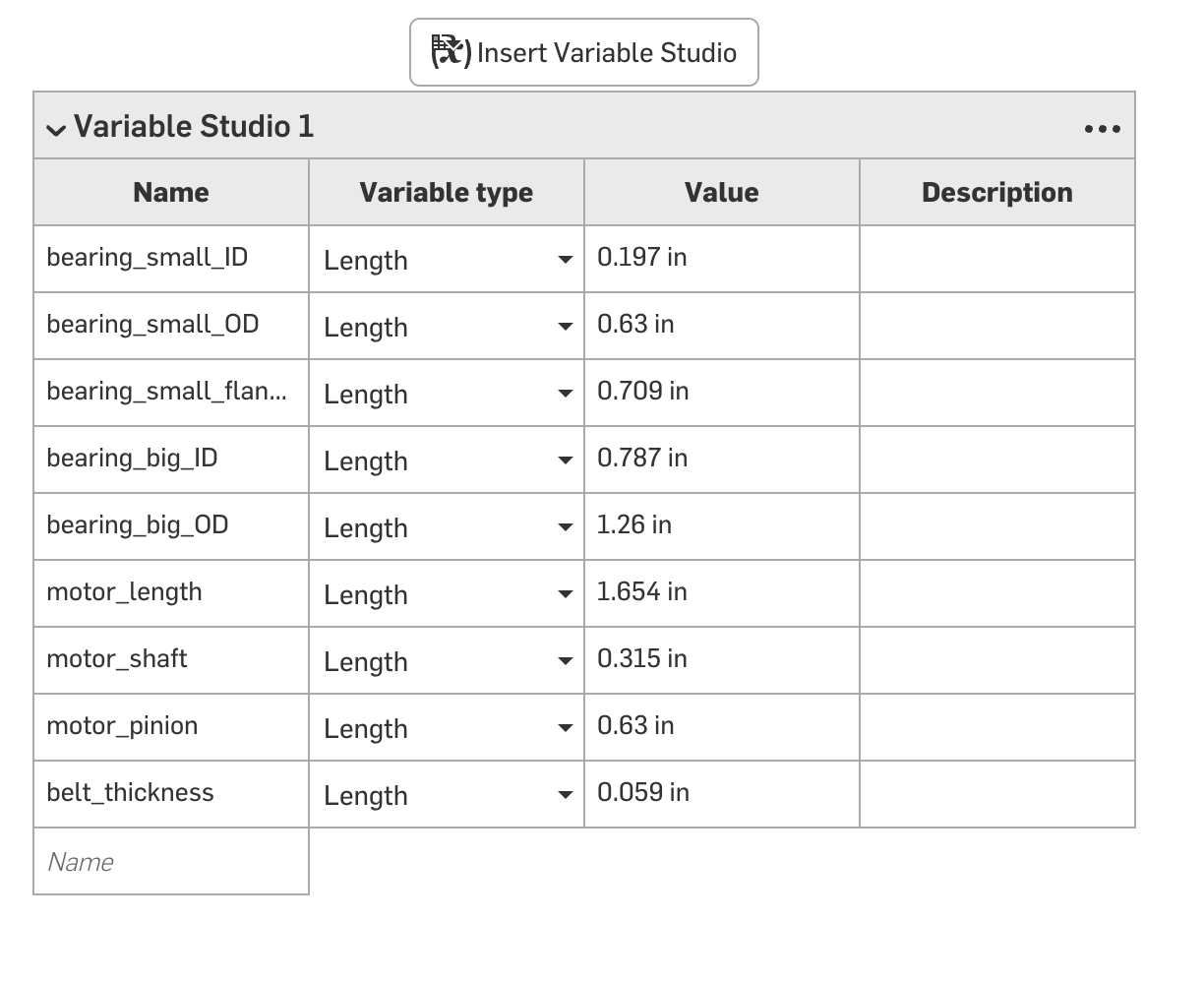
I am a huge huge fan of Onshape so that is what I am going to use and start off with a variable studio.
Some of the things I know I am going to use are bearings so I am going to make sure to have variables so
that I don't have to keep changing dimensions. Apart from that some of the bigger dimensions should also
be able to change without affecting everything.
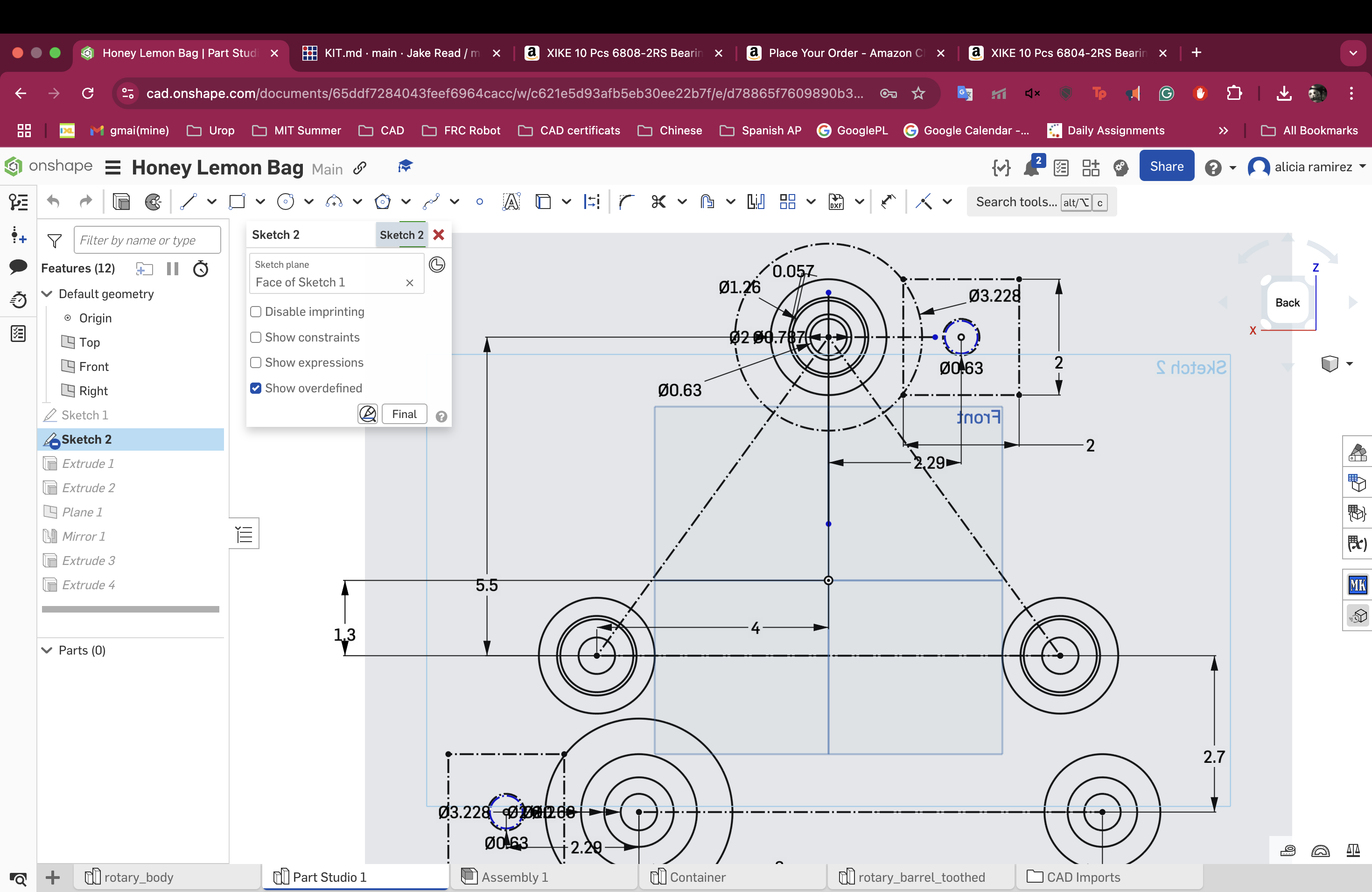
It is always a lot easier for me to start to design something by sketching it 2d with angles rather than jumping
straight into the CAD. So here are some sketches about how this is going to go down
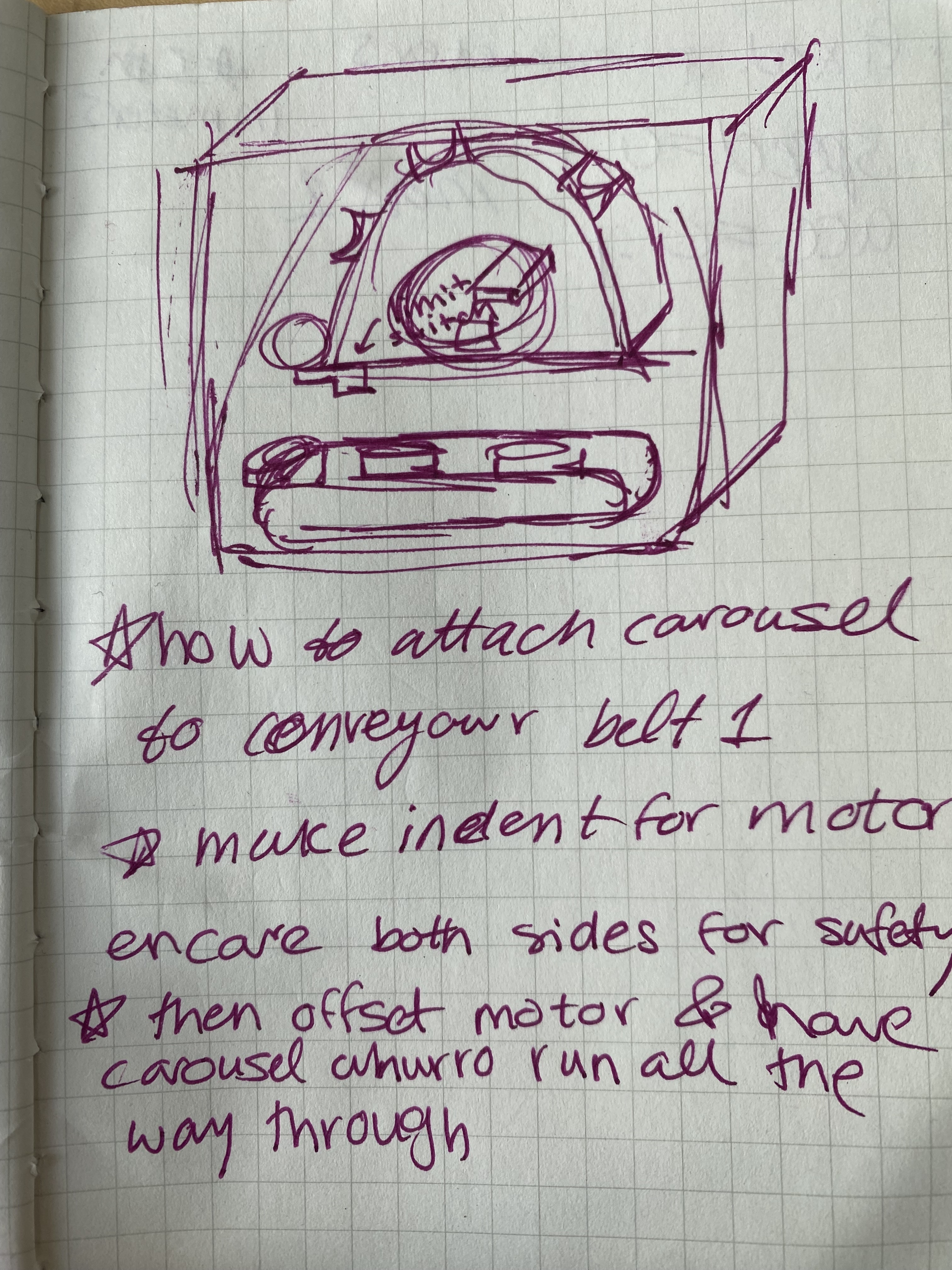
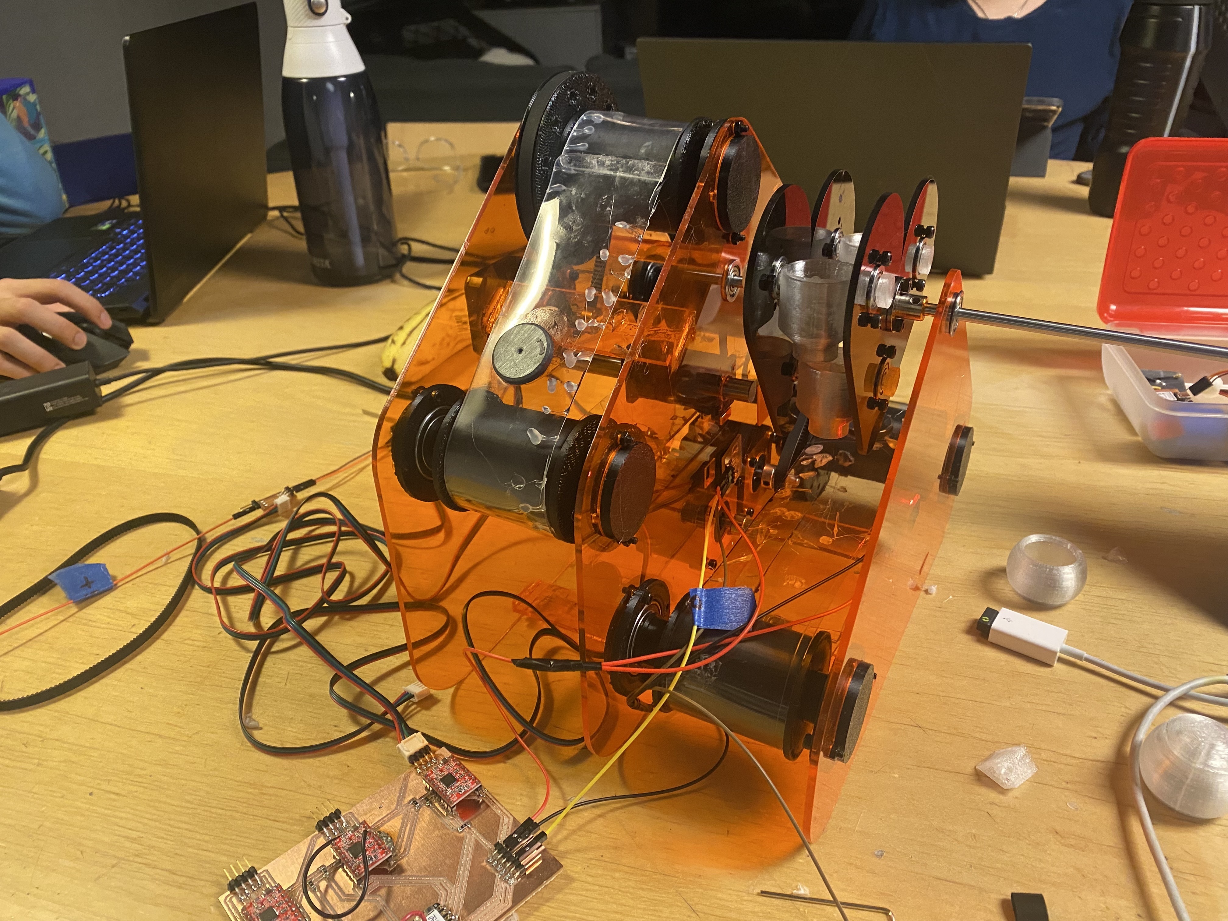
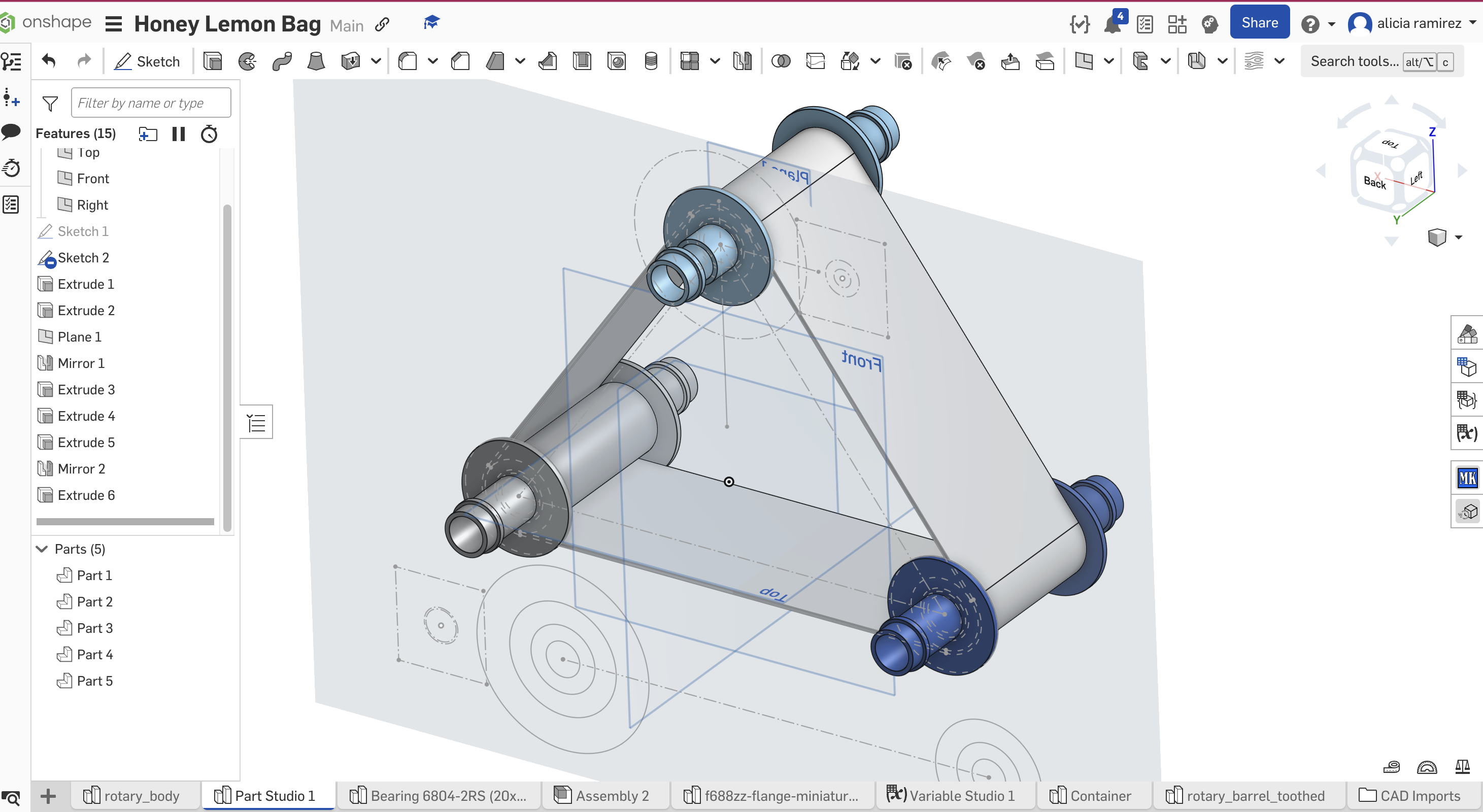
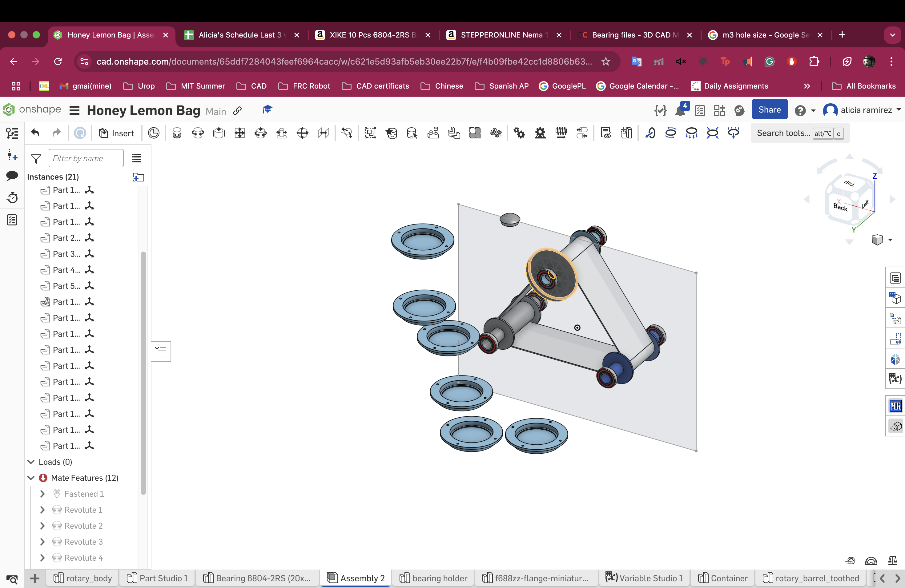
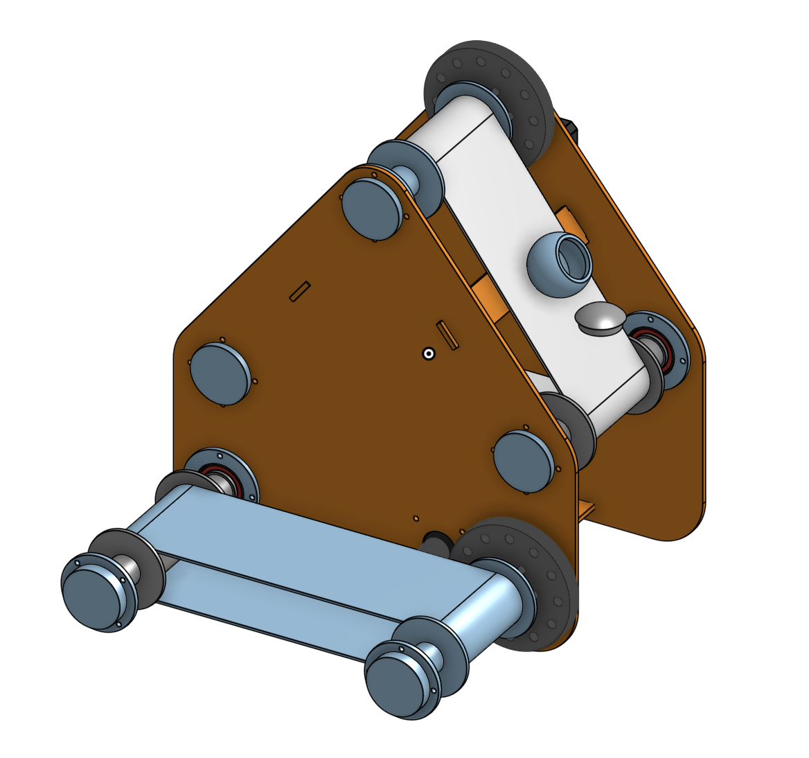
The way it breaks down is three rollers that work with a plastic as the conveyour belt. Right now
I am trying to figure out how to make sure the whole system stands up. The rollers need to somehow attach
to two plexiglass plates while still being able to smoothly turn. Only one of the rollers is connected to
a pulley and that in turn is connected to a motor but then the follow up question is how to connect those
to the plexiglass as well and then overall connect it to the other subassemblies.
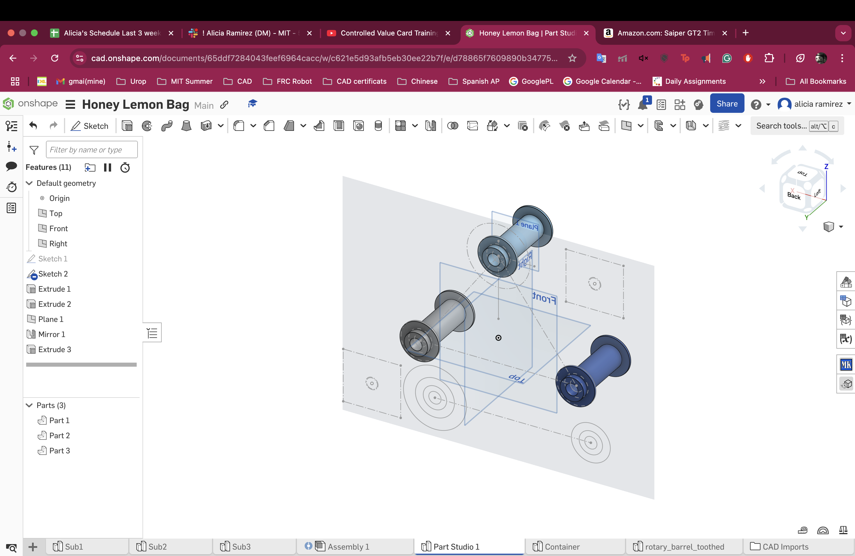
I started the CAD and decided I wanted a master sketch in this subassembly that everything else builds off of
and it is so so gorgeous and clean with the variable studio as well.
The only thing is the way I had imagined
connection the roller to the acrylic was by making it fit into a bearing that would fit into the plexiglass
and then I realized if I did that I wouldn't have a way to attaching the pulley to one of the rollers and the
motor as well. So I have to figure out a way to create enough spacing to put the pulley and motor.
I figured it out:
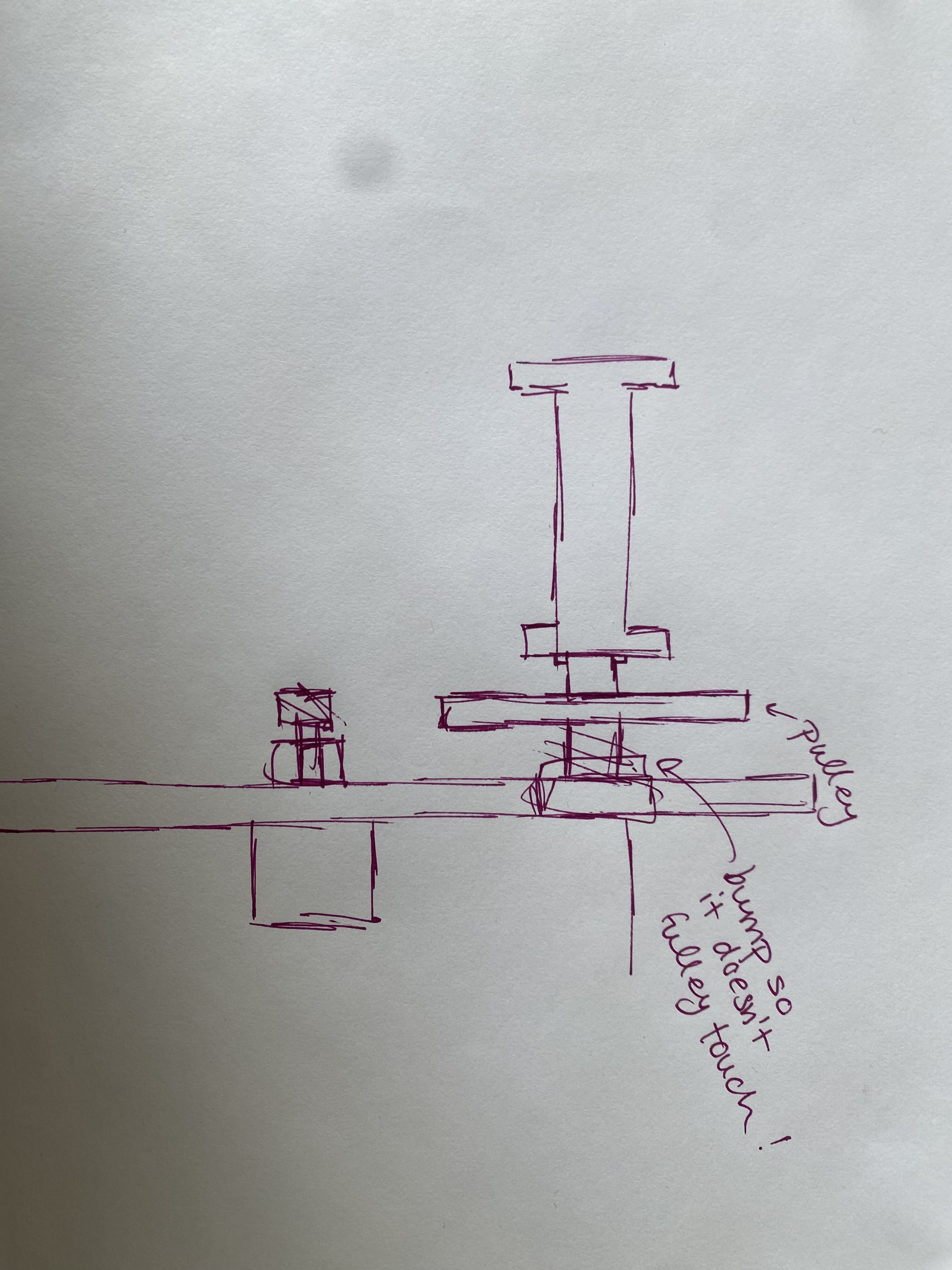
I can just do what i am doing and slice in a pulley into the middle. One thing about the pulley is that
it is an STL I didn't design so it is a little but harder to work with on Onshape but I can just export it
all together and it becomes one object. I also need to design if the case is going to be entirely covering all the subsystems
or if there needs to be some form of separation. Also I am kind of concerned that the bearings will just pop outbut i
can design something that screws onto the acrylic and holds the bearing in place because only the inside needs to rotate.
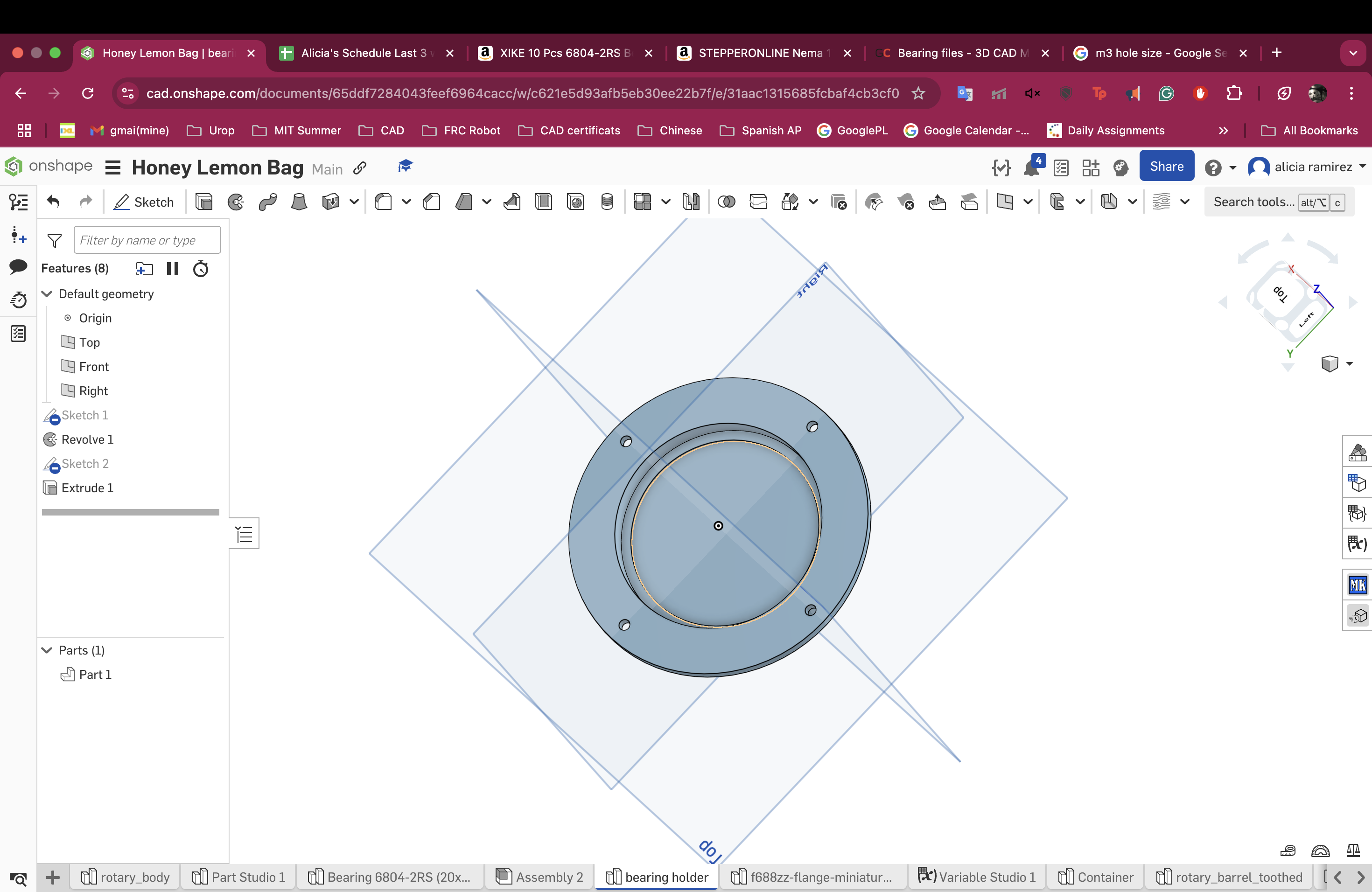
One of the reasons I love parametric design is because sometime you just mess up with the size and it makes your
life so much easier. For example my bearing holders... are the wrong size
but i can fix them super fast
All done!!
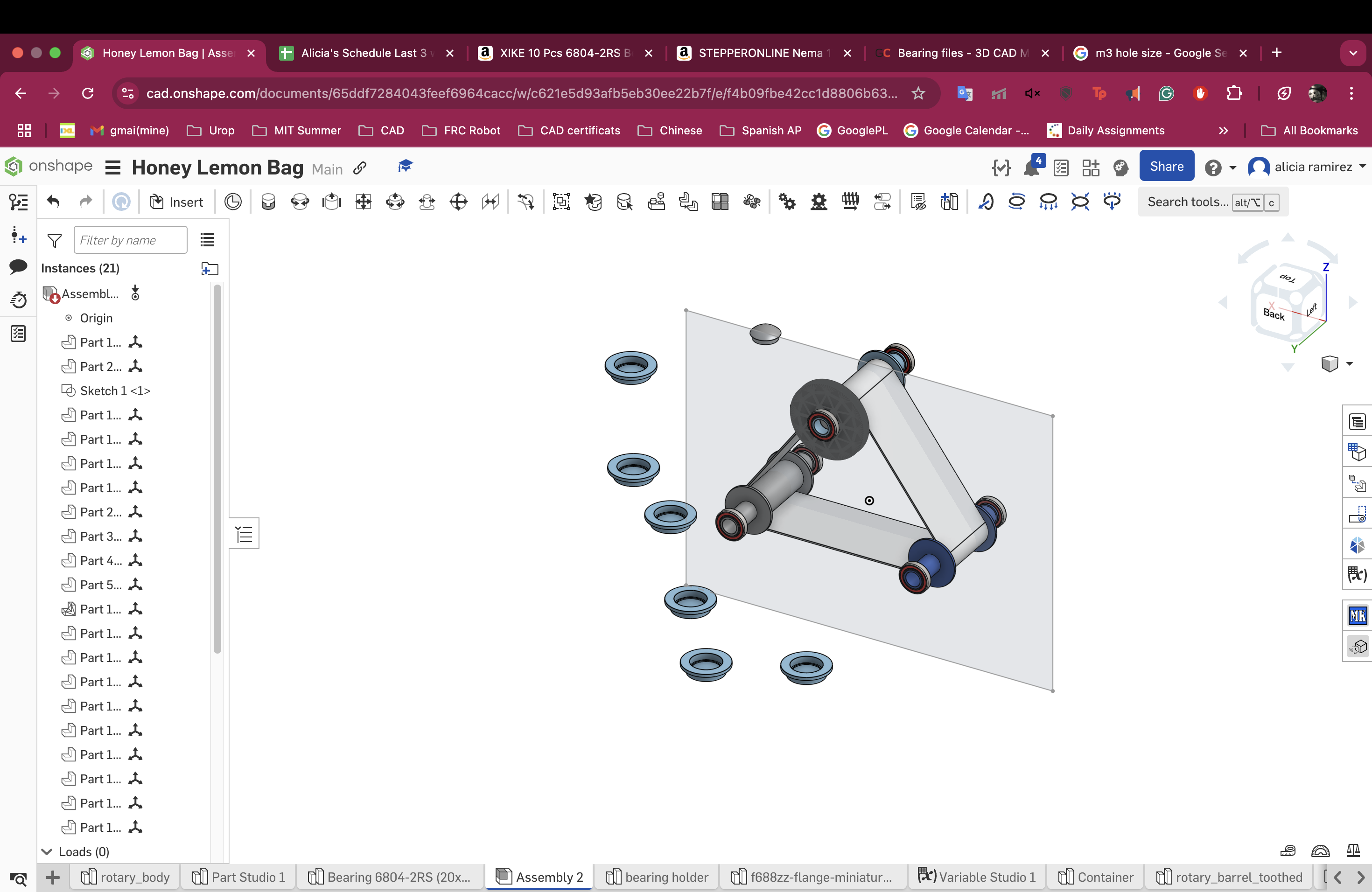
Subsystem 2 - CAD
The subsystem 2 is extremely similar to the first one except that it is not triangular. This means the base
is already made so I only have to remake the band and also maybe mess with the distance and the overall positioning.
I am a bit worried that I will be using too much acrylic and i dont know if that is something I am tying to fix or
if I am just going to try to find more acrylic. I am trying to design the acrylic in a way that it decides where everything
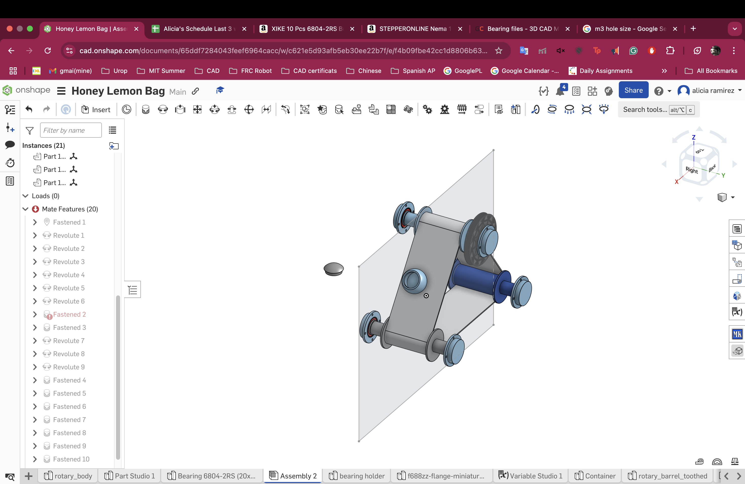
goes instead of vice versa and so far it looks kind of nice. It is actualy coming together really nicely. I think I
can fit the motors inside so that theyre snug and don't poke our making it look more clean and together. I am
admittedly concerned about how this assembly is going to go... I made steadying braces so it doesn't fall over apart from that
I need to make holes to be able to screw everything together. AHHH this is so exciting!! I just realized if the motor is inside
then the pulley is outside. Which doesn't work with my current design but it is not a big deal that the motor is on the outside.
I was even able to find the CAD for the motor and I am sure I can find CAD for m3 screws as well. this is going to be
GORGEOUS. I am finishing up the last acrylic and I love edit in context because I am trying to keep the consistency and
It allows me to see how it would actually look. I finally finished up subsystem 1 and subsytem 2 and now I am going to move on
to three but I haven't though much about how I am actually going to operate this one. I changed the CAD to make it shorter
allowing the radius to be bigger so hopefully the container can pass more smoothly
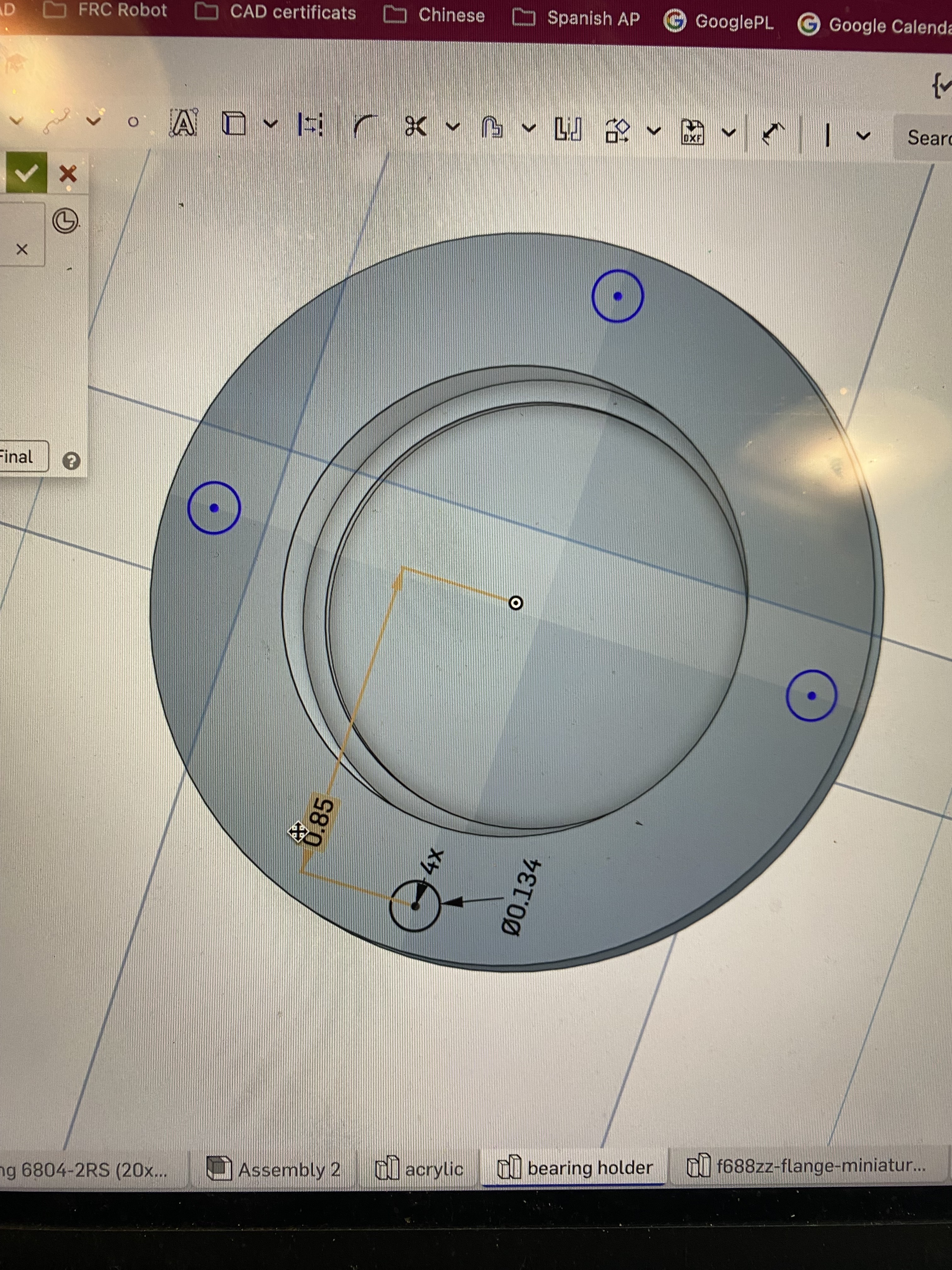
Subsystem 3 - CAD
I had a few ideas on how I was going to drip the paint at a correct speed and the initial idea I had was something that
had a servo attached at the bottom and it would open and paint would fall out. After doing some more research I found
a teapot that has a small marble and a magnet which moves the marble to the side allowing tea to flow out. I really like
the idea because that involves simplifying the mechanism allowing for less fail points. The only way is I dont know where
I would mount the electromagnet so that it is always in the same place meaning it can't be on the carousel but I don't
know if that would make it too far from the marble for it to do anything. I am also making the carousel in the shape of a
heart to parallel the screen on honey lemon's bag. I keept making adjustments that break things which I really should've
thought out before by making small subassemblies that would adjust themselves correctly to any changes. I also have no sense of size
so I am making these paint containers without actually knowing how much paint I would need or how big they should be.
I fixed all the assemblies so they are now subassemblies and it won't all simultaneously break on me with me having no
idea what is actually wrong with it. I've been thinking about how I am going to deal with the dripping paint since I don't
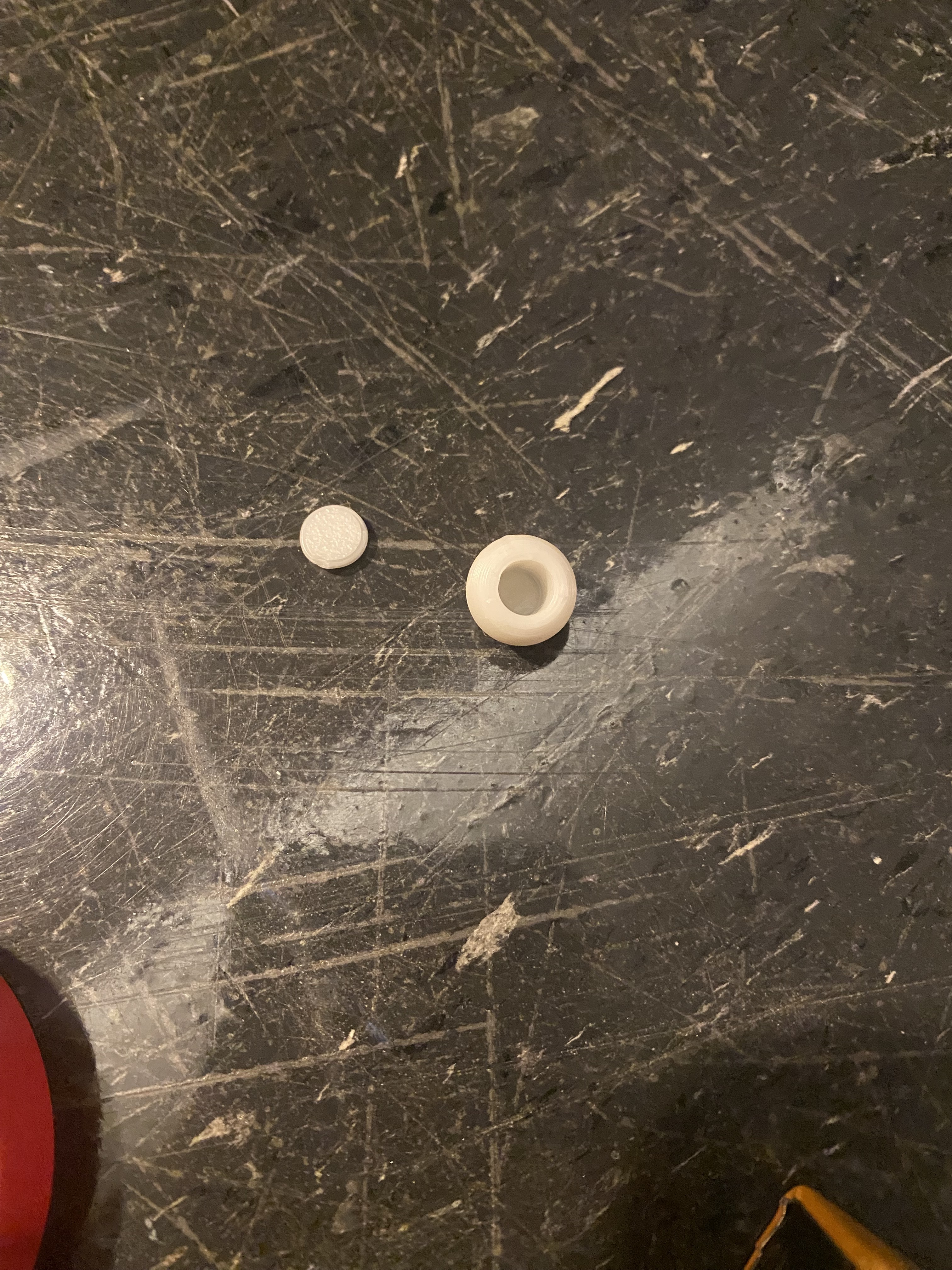
want to buy 100 marbles for $10 so I broke open a ball bearing to steal the smaller metal balls.
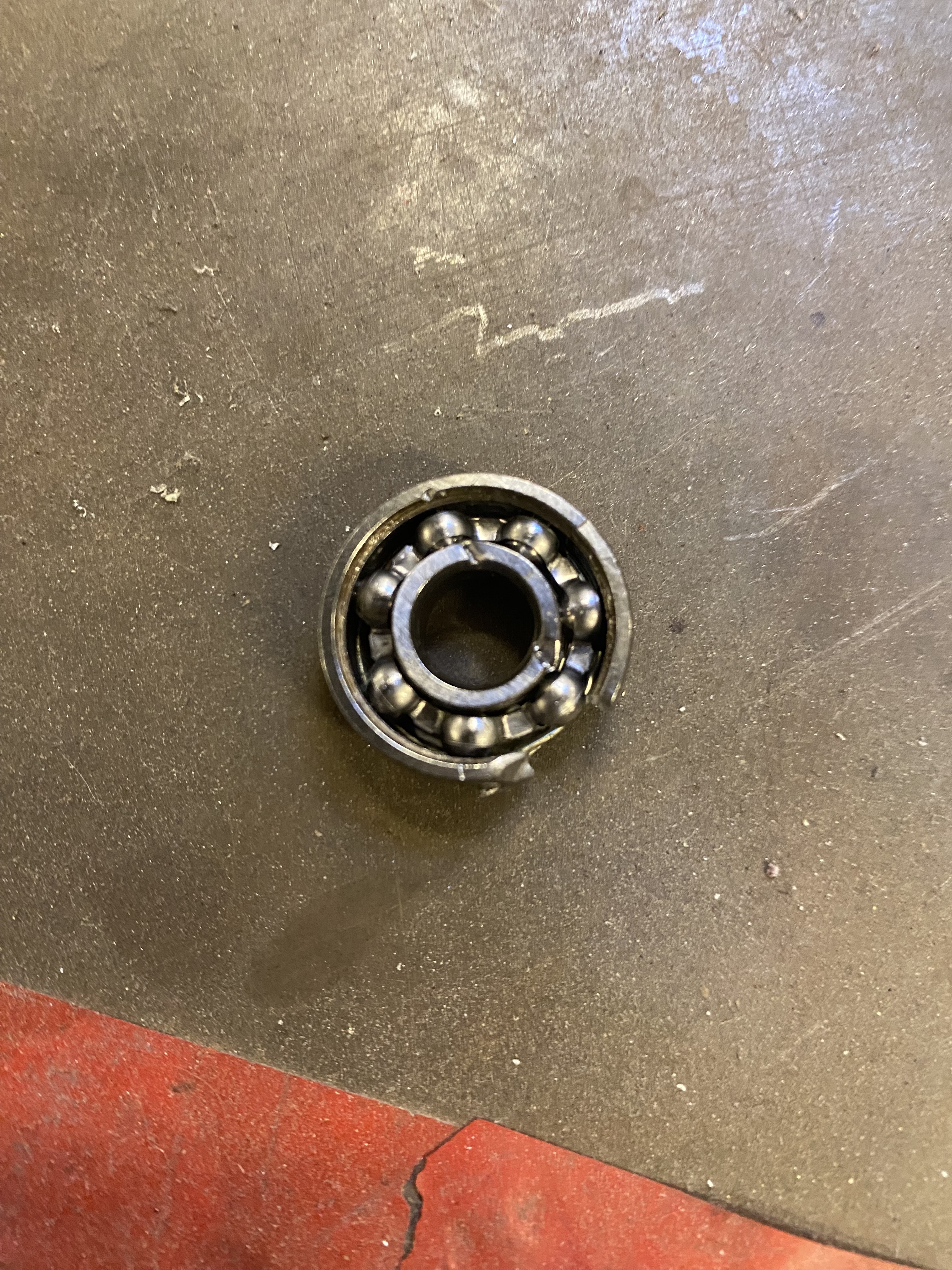
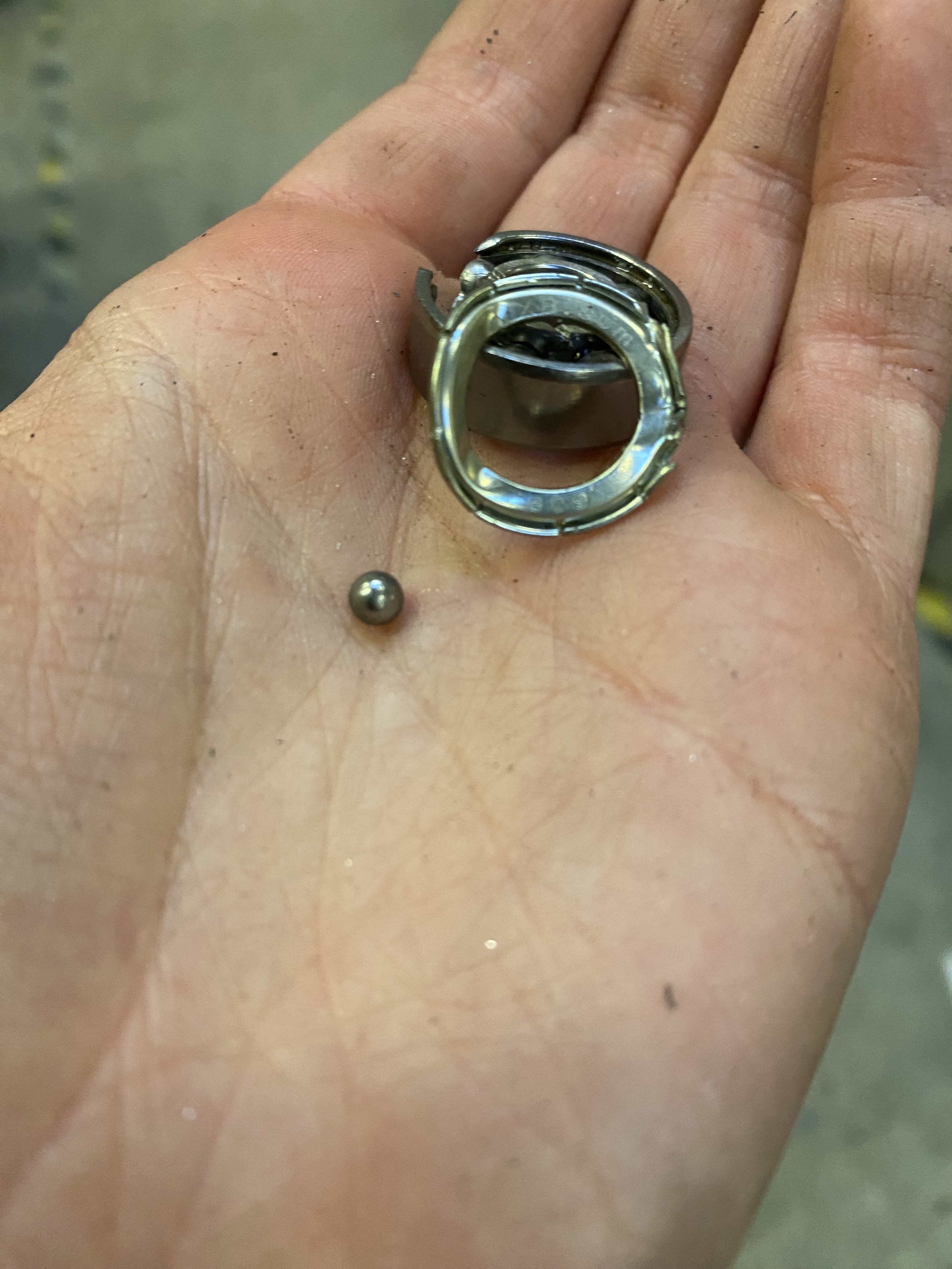
but it didn't work
because they are too small so I am thinking about putting some sort of nut or something metal inside a 3d printed ball in
an attempt to make it act metallic. Okay so update apparently I can put some magnets inside and create a sphere similar
to the paint ball one and just glue it shut. I am super excited about this!! Okay so I set it to print and I should be
able to see the results in about 10 minutes. Okay so update it didn't print very well because I did not account for
tolerance so the magnet did not actually fit inside. I printed it again and it was a bit bigger but it broke off at the
bottom.
Apart from the electromagnet I think I am almost done with Sub 3 I may just be missing how to attach
the paint containers to the heart carousel. I think I might make two hearts and use shaft collars to keep them in place?
Or I can 3D print a shaft that maybe might be thick enough for an m3 to be tapped into it with a washer to keep it flat.
Fun update apparently my paint containers run directly into the shaft that spins the carousel. soooo i messed up. I
am not entirely sure how to fix this. I think I might leave it because since it is technically due to weight it might just hit the
shaft and deal with it itself as long as it does not spill paint
Electromagnet Sidequests
So I am trying to find an electromagnet for my subsystem 3 (the carousel) and I emailed anthony and he said I could use a
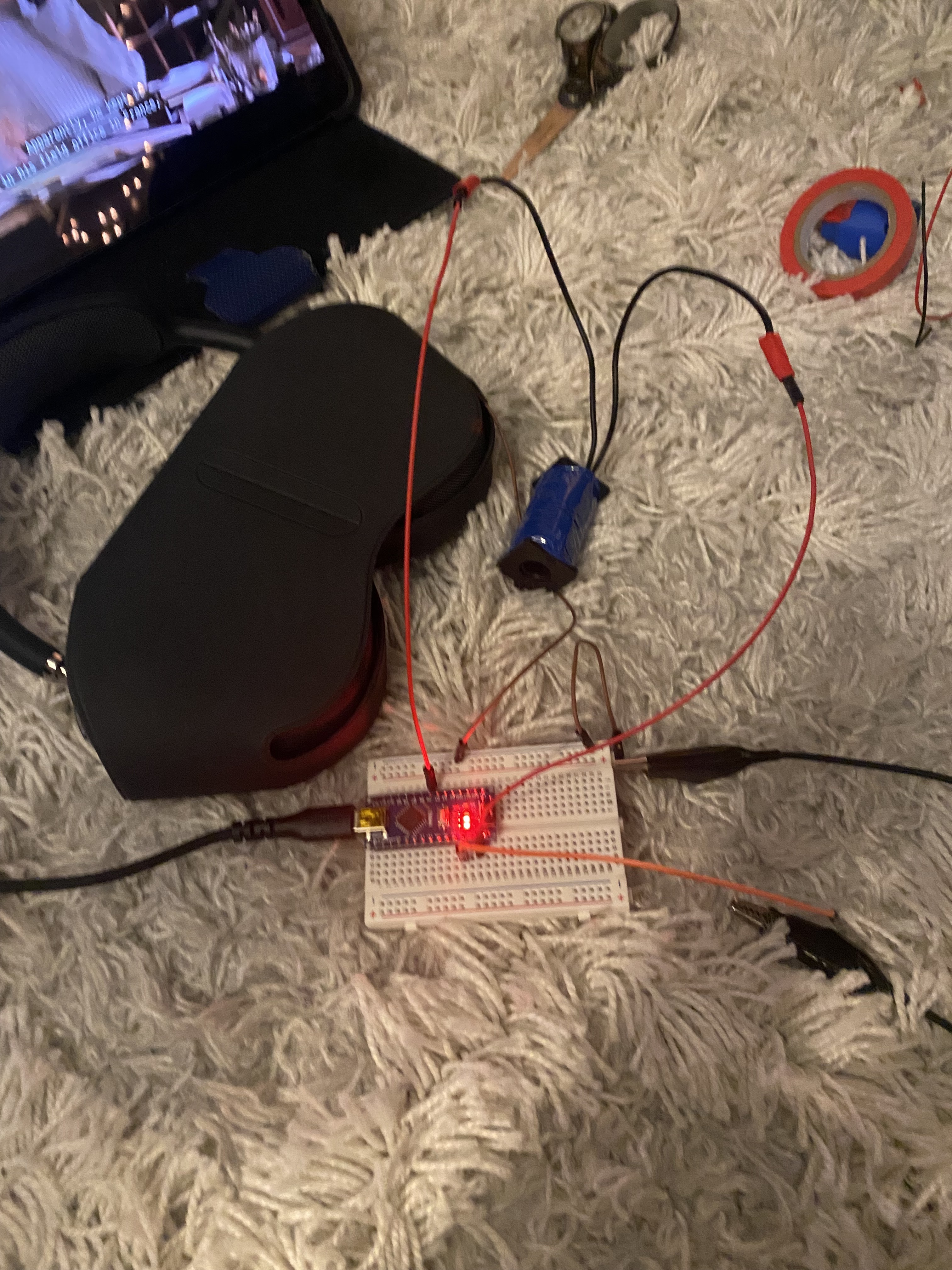
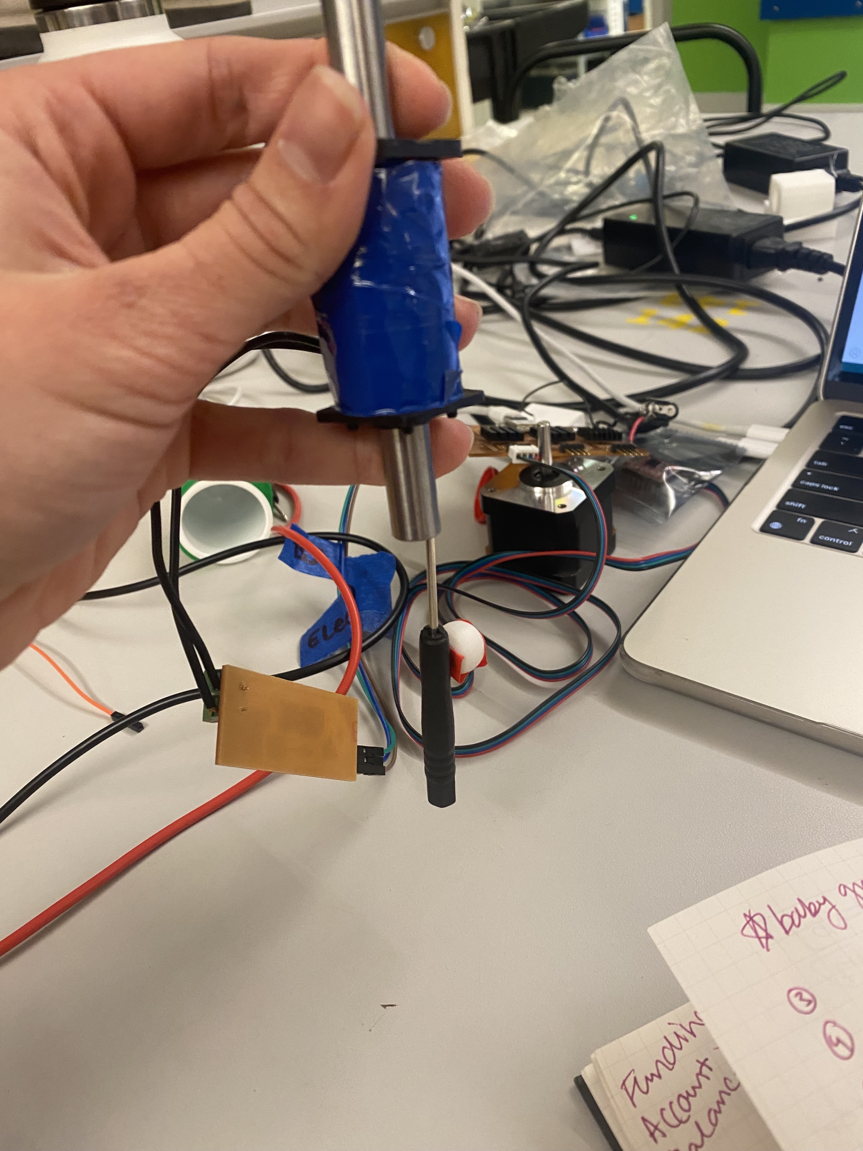
solenoid but caveat I have absolutely no idea how to do that so I guess we're about to find out wooo. I am back and
it seems to be relatively straight forward if you give a solenoid current it turns into an electromagnet so I should
be able to connect it to a digital pin and give it high and low signals which would turn it on and off. Let's find out.
I am not sure how i can prototype this but I think I can get an arduino nano and stick some wires into a breadboard
because prototyping with esp32c3 is very hard on a breadboard because the connections aren't the best. my breadboarding is working with the bare minimum so I have no idea if this is actually going to work
apparently there is not enough current without adding more to it. I think I might have to head to OH or EECS today
to figure this out. (Follow up in the electronics section)
Pulleys and Belts
One other thing I am worried about is that I need a specific pulley but I think that the pack I bought are all different lengths and so I don't know if i am going to need to calculate so that it works or somehow scrounge up two more belts. So I decided to make a table knowing that my smaller pulley, an 8mm motor pinion, is .315in and my bigger pulley is 3.2 inches with the belts I have only the 280mm,300mm, and 400mm lengths work giving me center distances of 2.298,2.771, and 4.903in. Which I think may actually be really convenient.
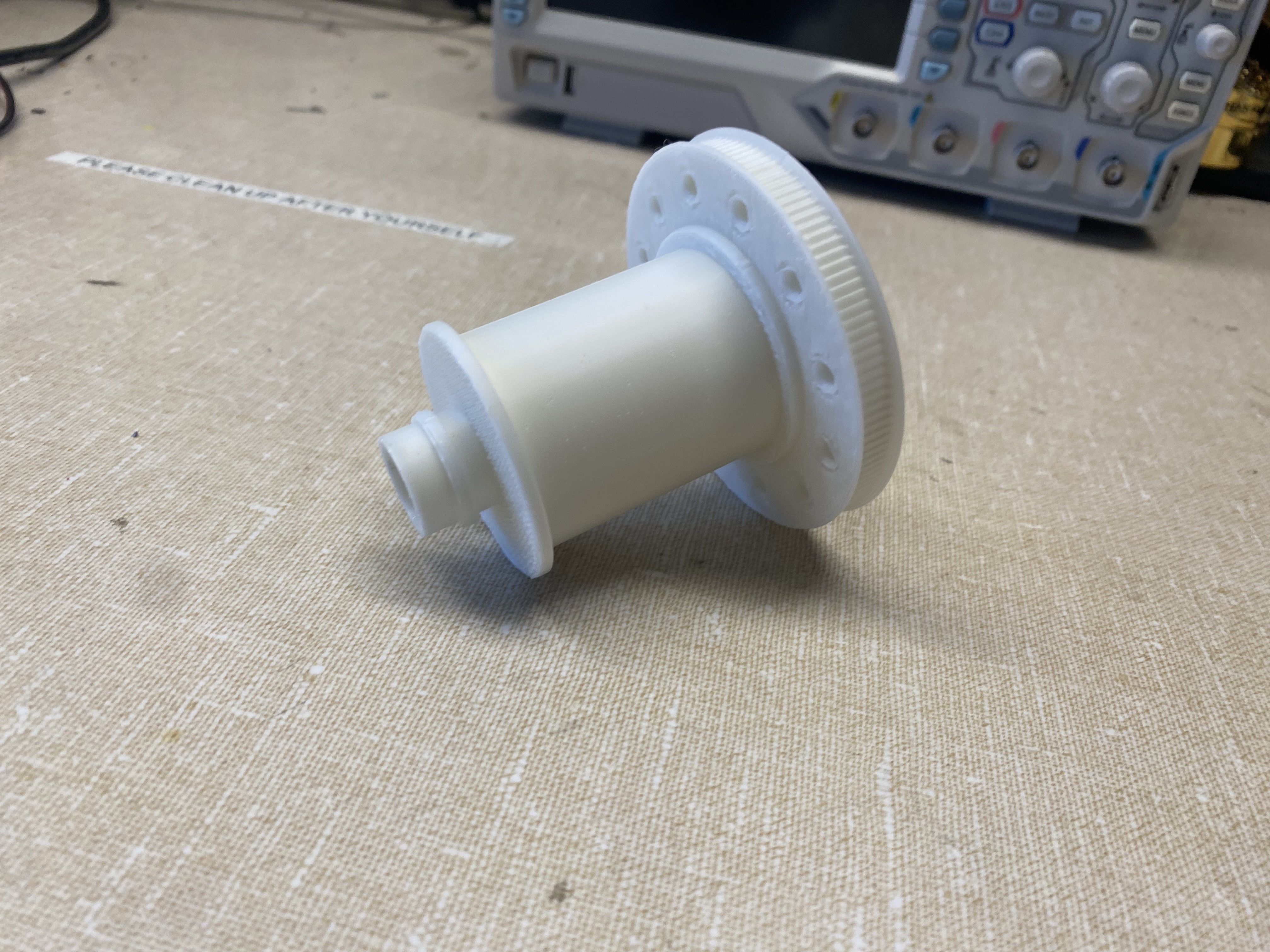
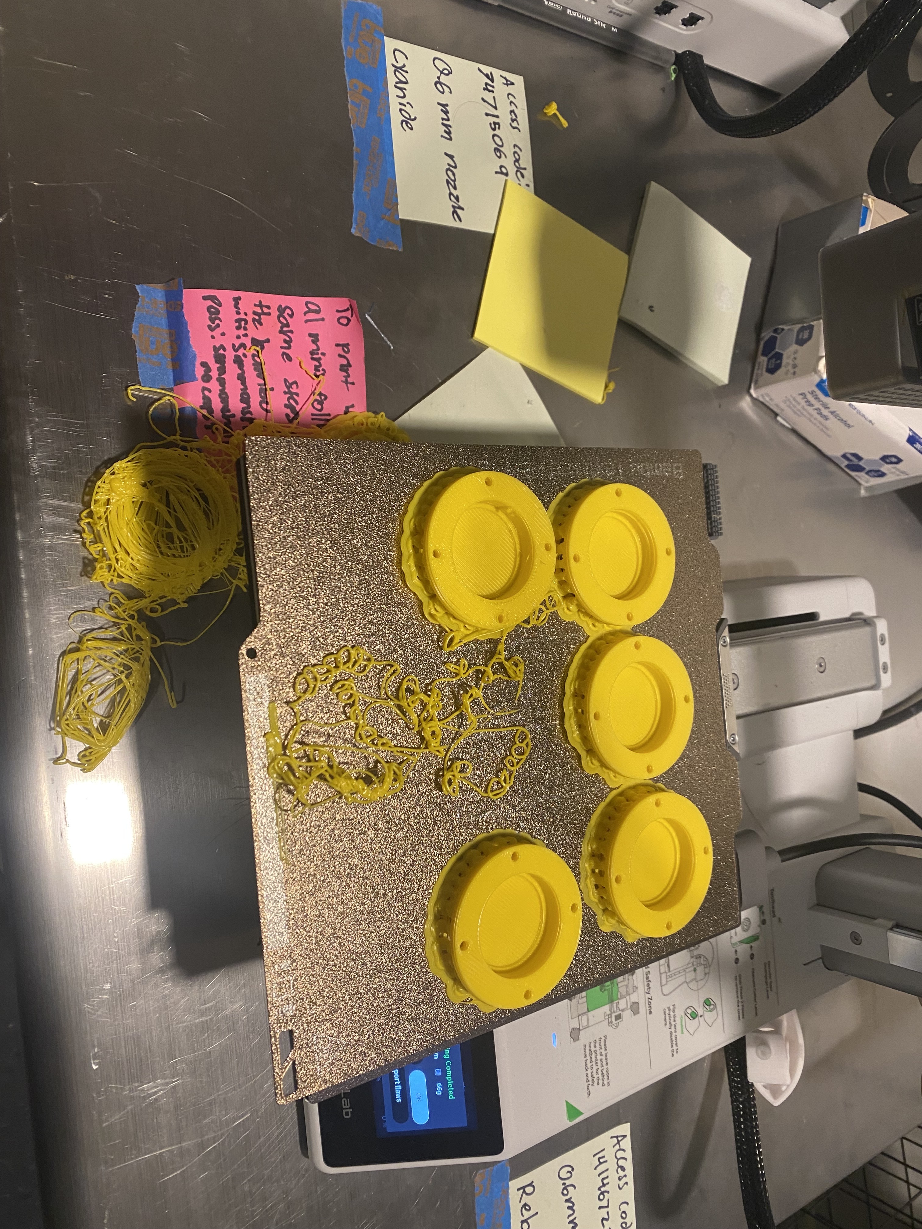
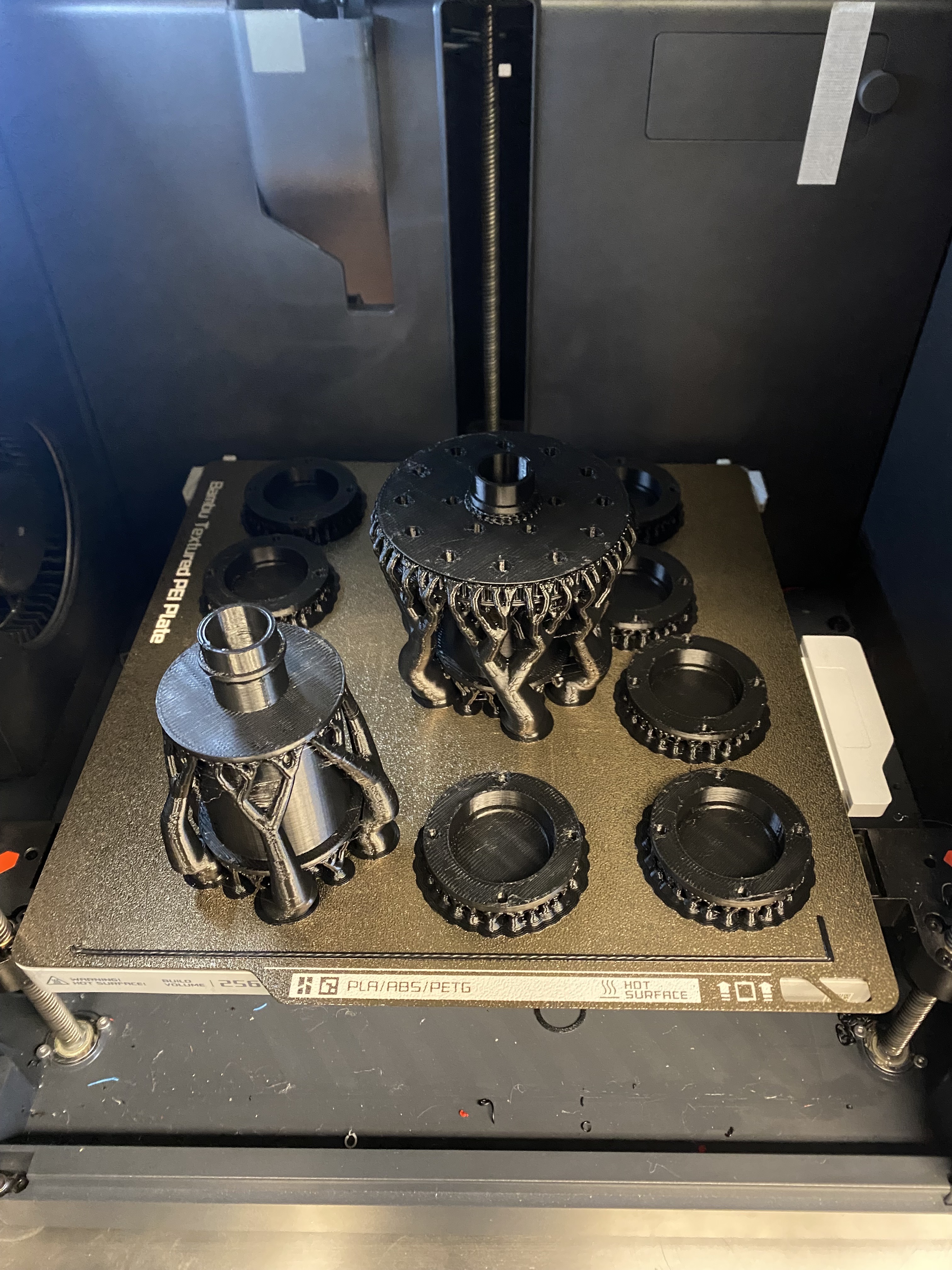
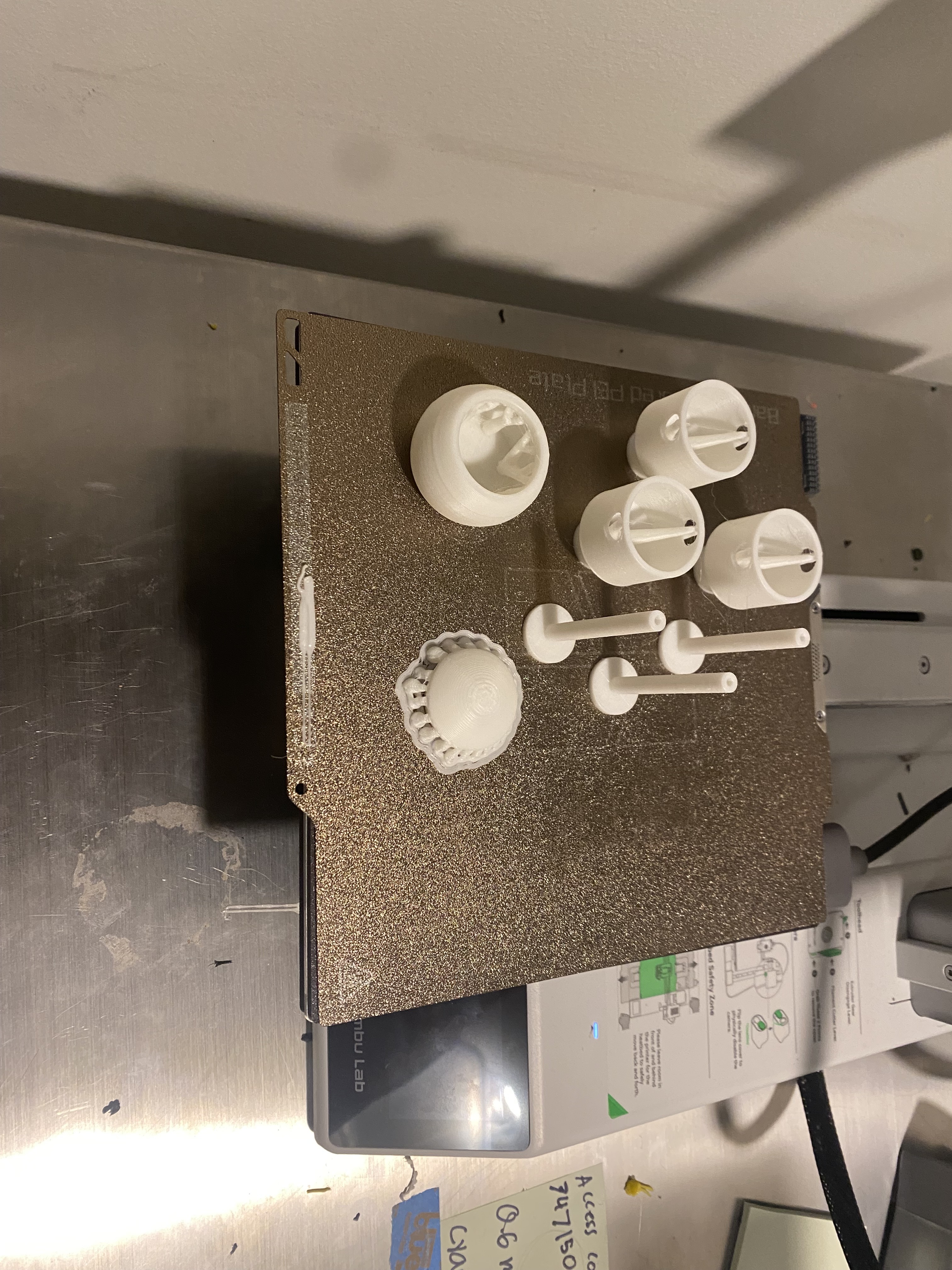
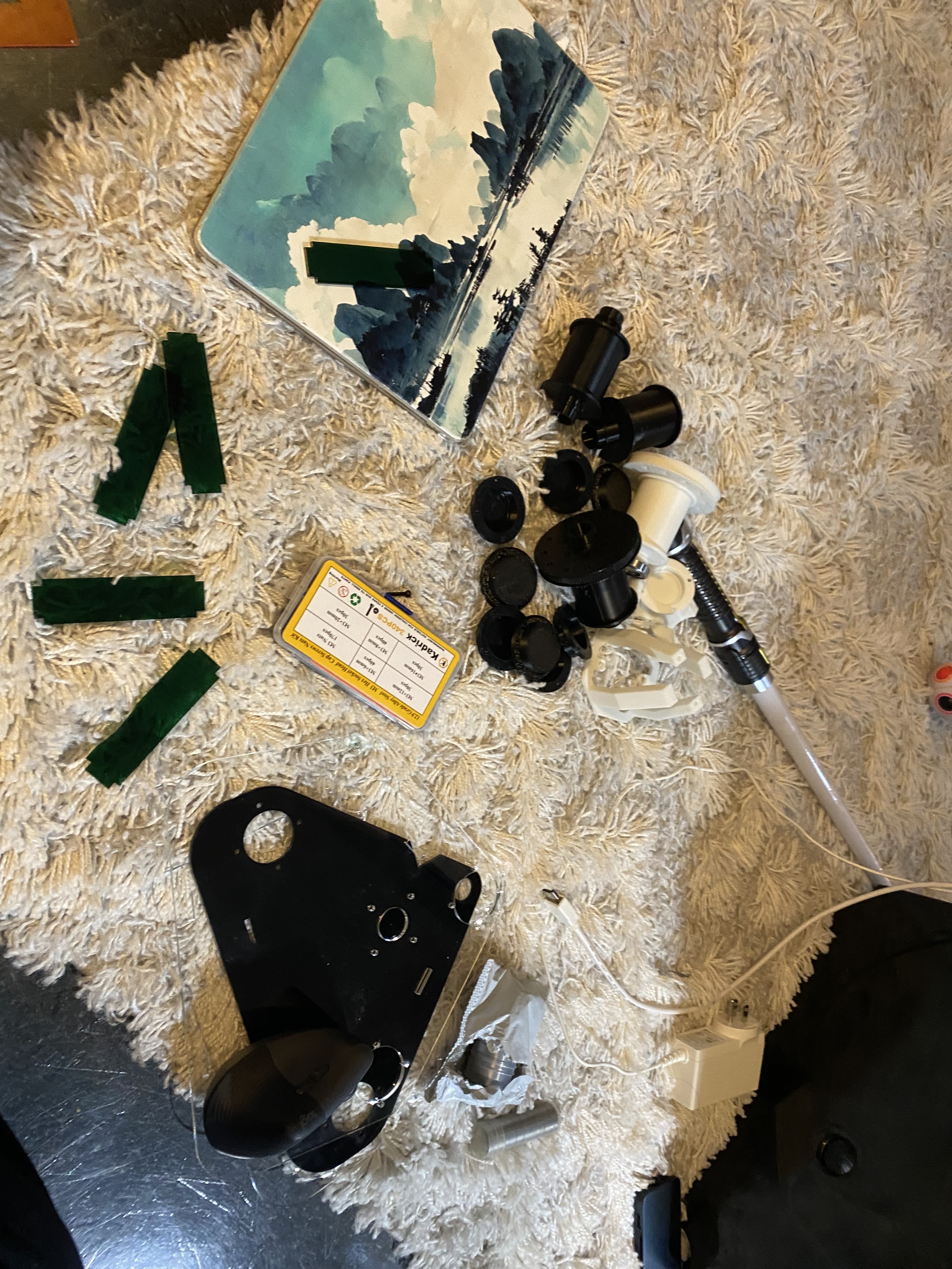
Some Test Prints
I sent three things to print: the roller with a pulley, the roller without a pully, and the paint container.
THE FIRST PRINT CAME OUT. well the first first one just turned into spaghetti but this one came out super clean.
I need to make sure the belts are the right scale but it looks gorgeous.
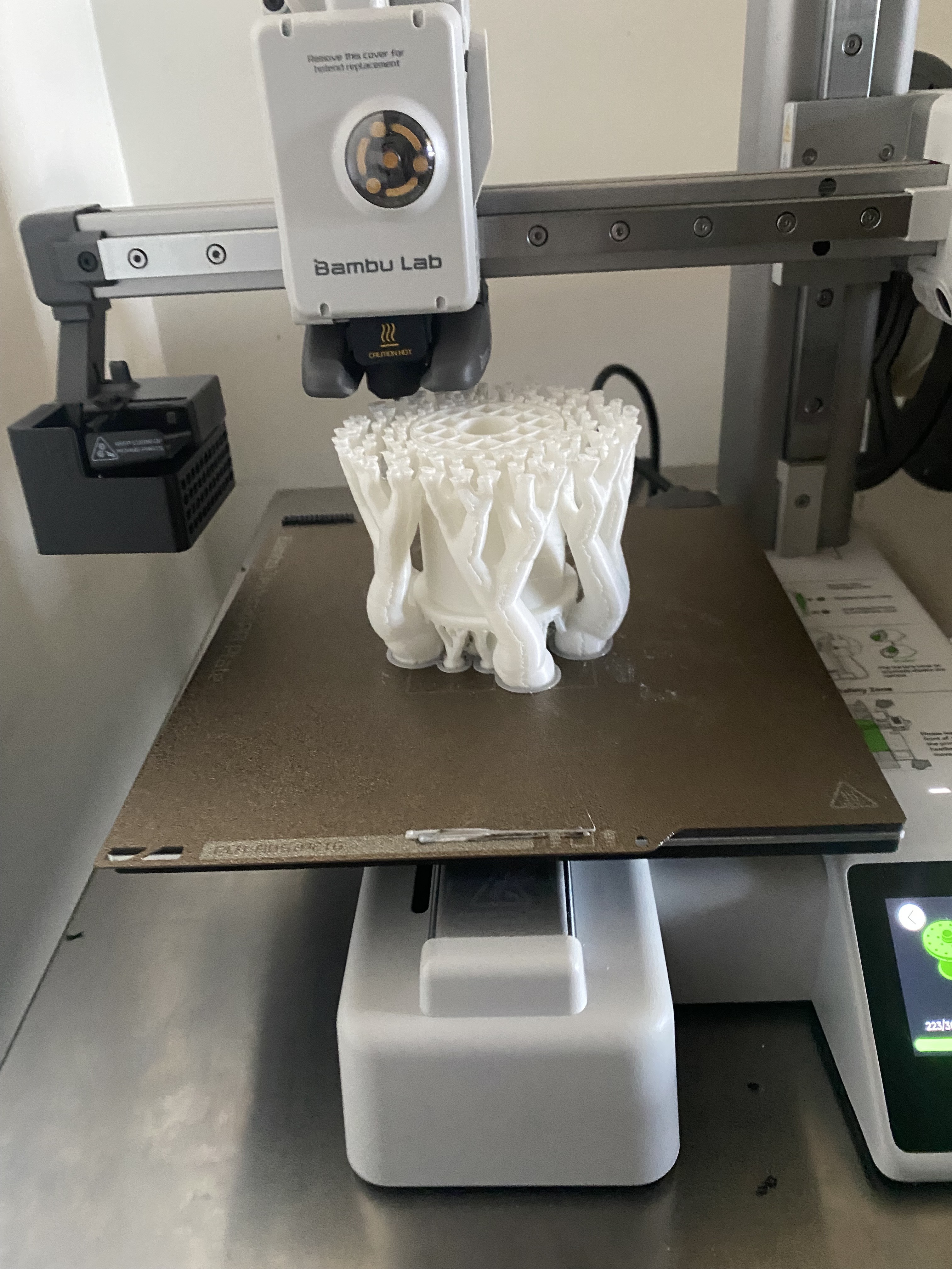
My next set of prints is going to be
my bearing holders and one more roller so I can hopefully assemble the first system and maybe a container with
a bigger tolerance for the magnet.
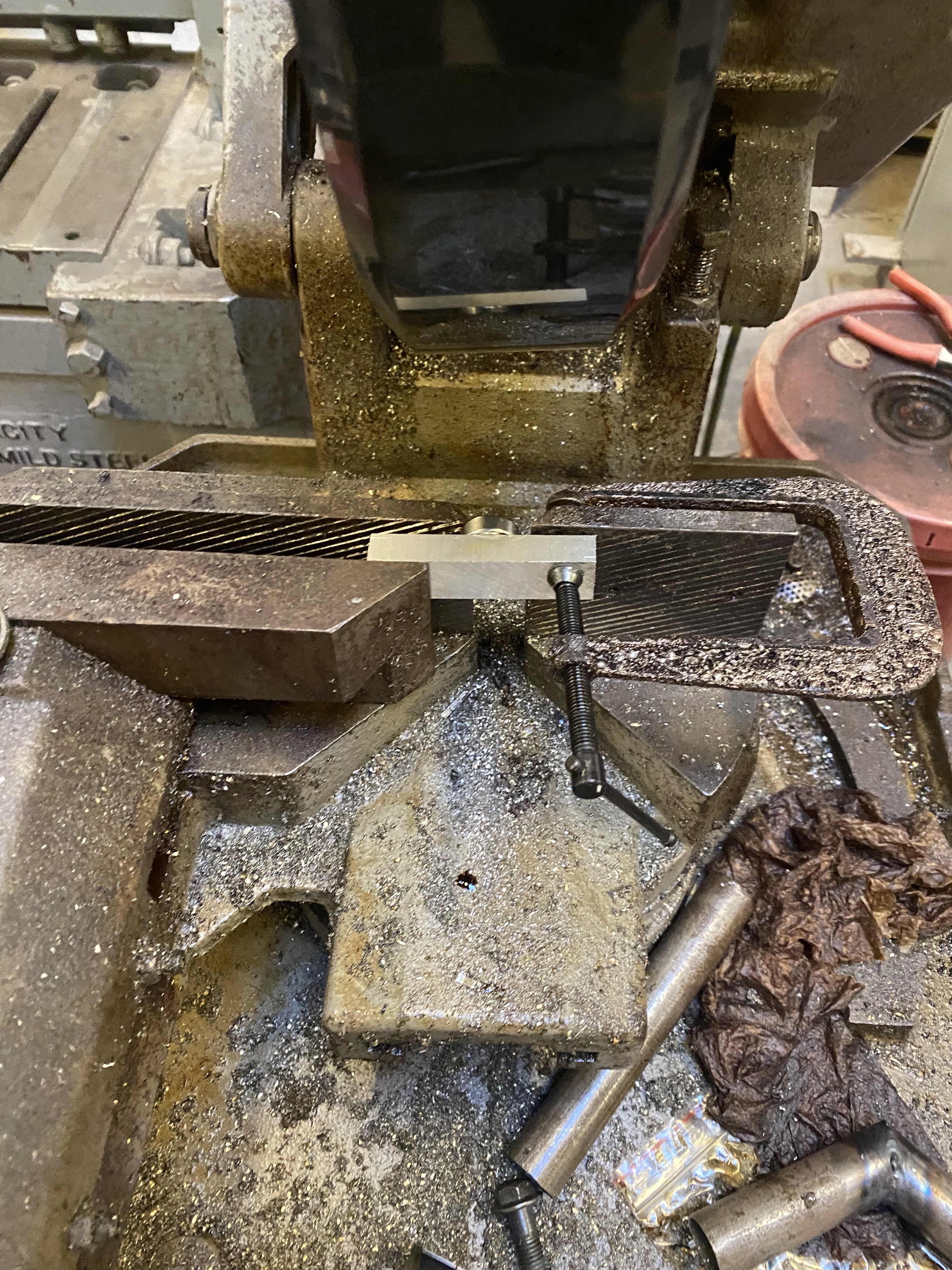
prototyping
I am thinking about prototyping today using cardboard to see if all my dimensions will work and then maybe doing some
small tolerance test cuts on acrylic to make sure I don't waste my special acryilc. I was actually able to cut out in the
EE lab of my dorm and to all the tests. After this I am going to go to metropolis and actually cut it. I was actually super lucky
with this because it didn't work with my computer because the laser cutter connects with ethernet and apparently macbooks
don't really have ethernet.
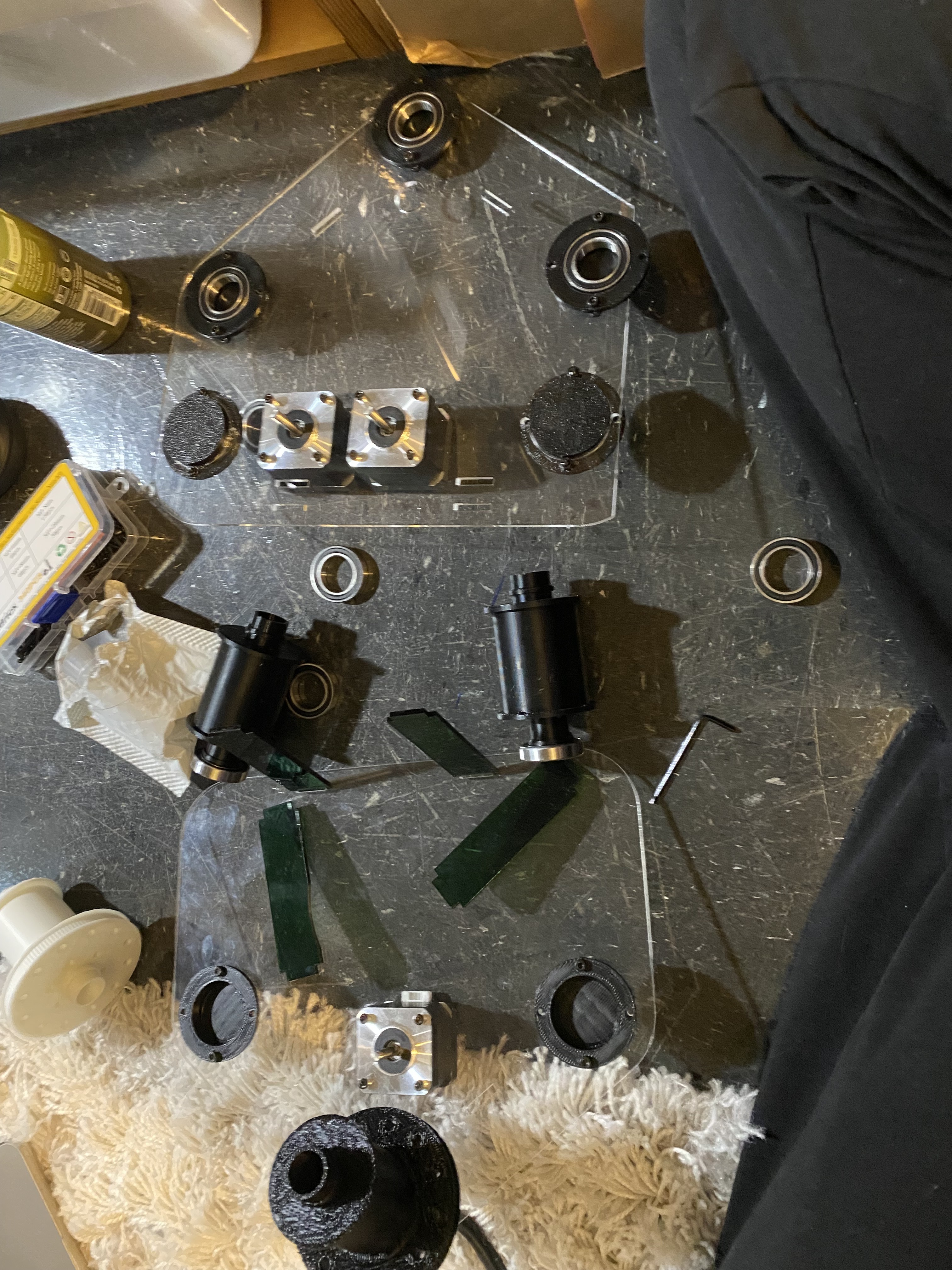
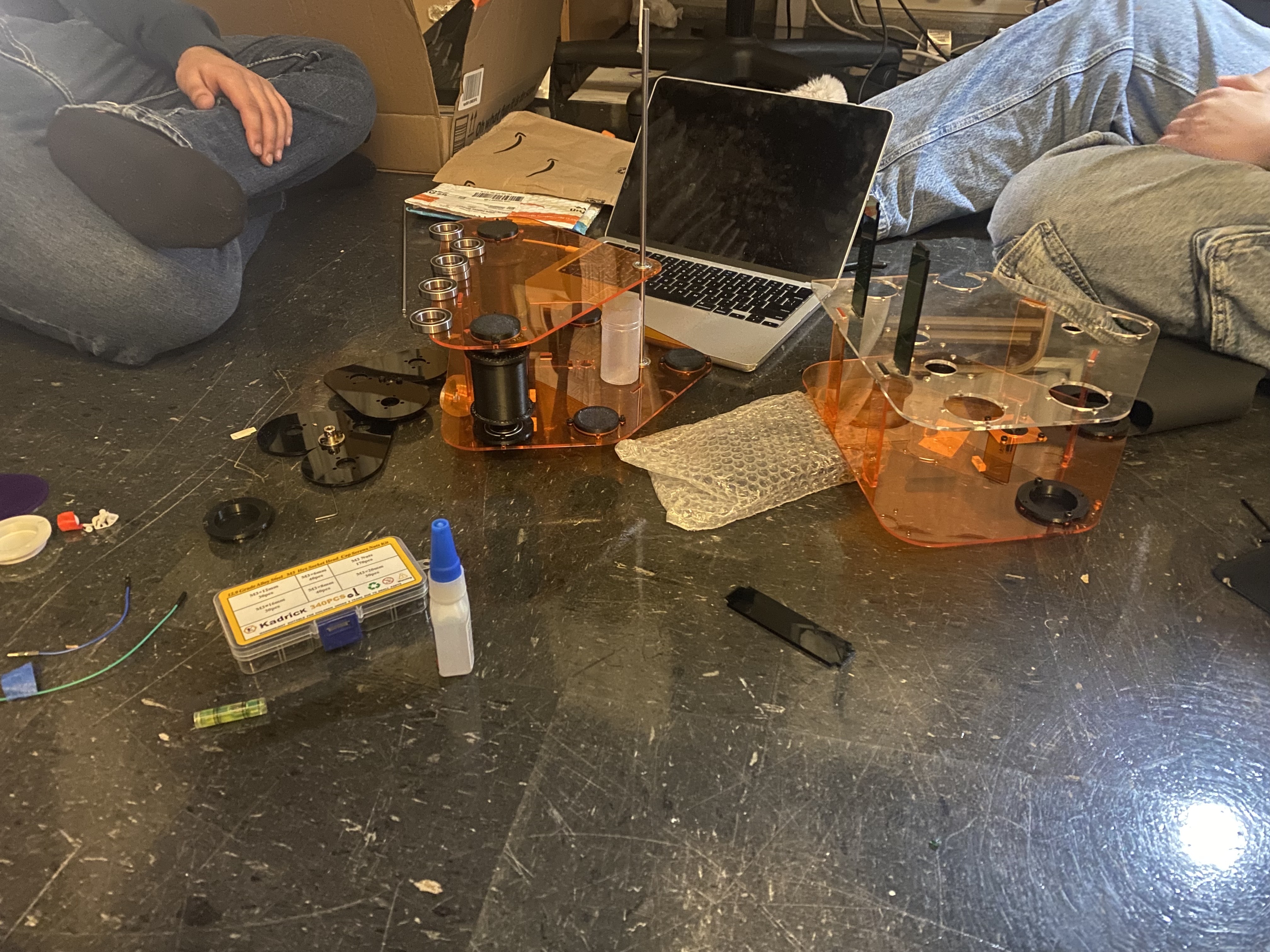
There was someone in metropolis that was able to help me cut it and I started assembling it
but I ran into some issues, for one the bearing holders fit in the first two but not the third acrylic, the motor pinion
that I bought was 8mm instead of 5mm and that was mostly all the problems. Everything honestly fit together really nicely.
I am a bit concerned because the shaft collar didn't really fit that well on the shaft put I did not maufacture or produce
that so I don't know how to fix it and unless it's a metal I can drill I am not sure I can fix it at all. I was able to
cut out the rest of the acrylic so I can now mildly assemble the full prototype apart from the belt shaft stuff. This is so exciting.
The heart seems a little bit small and I am worried about what is going to happen when I put it all together. Apart from that I am a bit worried about how
close the holes to the nearing moutns are because I don't really need it to be that close and it is almost cracking. Apart from that I forgot
about holes for screws to mount the smaller bearings but heyyyy it is fine ig?
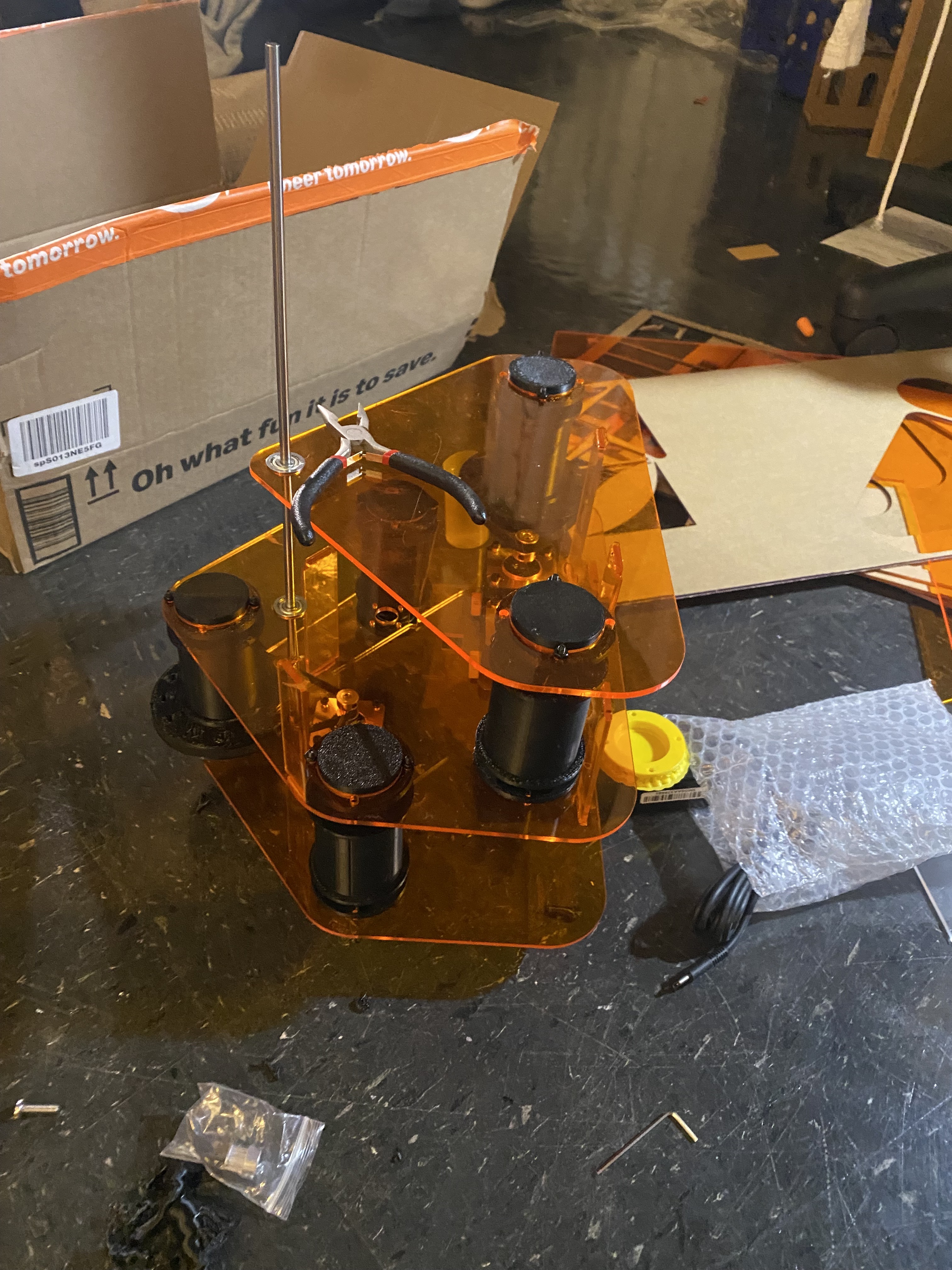
I am putting all the first prototype together minus the pulleys and motor pinions It is pretty hard to attach without it all falling apart
apart from that the axles that hold the paint containers are too thick so I need to make them a bit smaller and I might just
print the shaft collar and see if that works and I am also the other heart which I forgot to cut out.
The shaft collars now fit but for some
reason my CAD was off so the bottom acrylic doesn't fit on correctly and I am honestly not at all sure what just happened.
But I think I can still test the rotating heart. I tested it and I am extremely worred that the heart isn't going to work and the paint
canister seems poised to tip over and spill all the paint. Apart from that the way I am holding the paint needs to change because apparently
the size between the inside and outside of the axle is so miniscule a 0.6mm nozzle cannot print it well. so it doesn't even slic with it as an option.
I think I am going to make the heart bigger so that the paint doesn't spill over as well but it cant be bigger bigger or else it'll hit the
conveyour belt it just needs to be further from the axle in the center. I was able to move them out in the same size heart and there seems to be
no conflicts YAY. Now I just need to figure out how to mount the paint containers. WAIT okay so I think I was giving it too much freedom. The container
doesnt need to spin on an axle it can be fixed to the axle because it spins on the bearings.
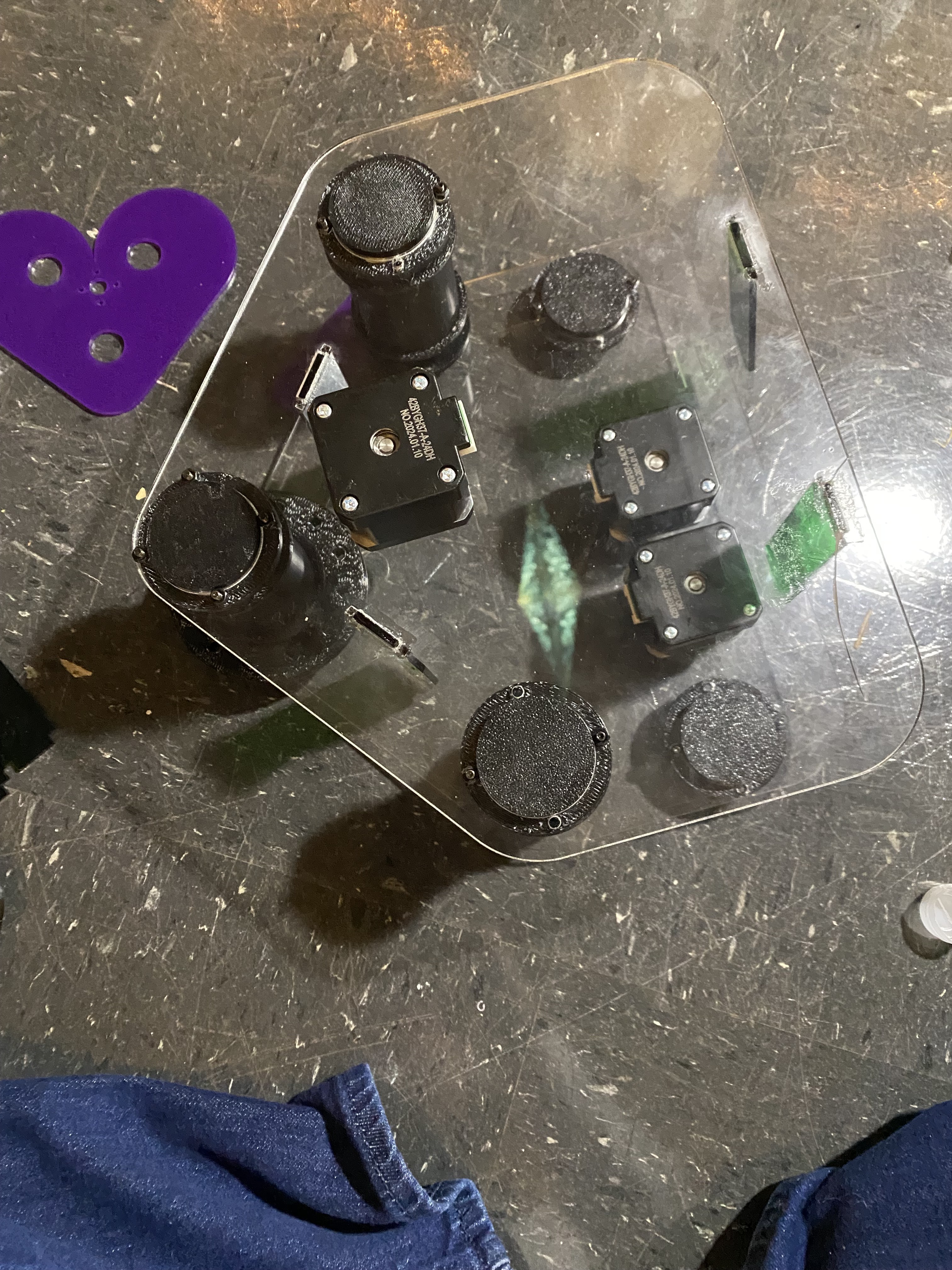
I was able to add in some cuts for the phototransistor, electromagnet, and I made a really small holder for the
limi switch. I have no idea if it's going to work but I finally cut my final parts for the project and I am
so excited the colors are so clean. I am probably going to put it together tonight after studying for 2.003
Today's milestones are getting the main PCB done done so that the motors actually turn the correct amount,
getting some basic code for the limit switch, and combining all the basic code I currently have for all
the subsystems into the webserver code. If the PCB I am currently milling does it's job then overall
today's work should not be too hard.
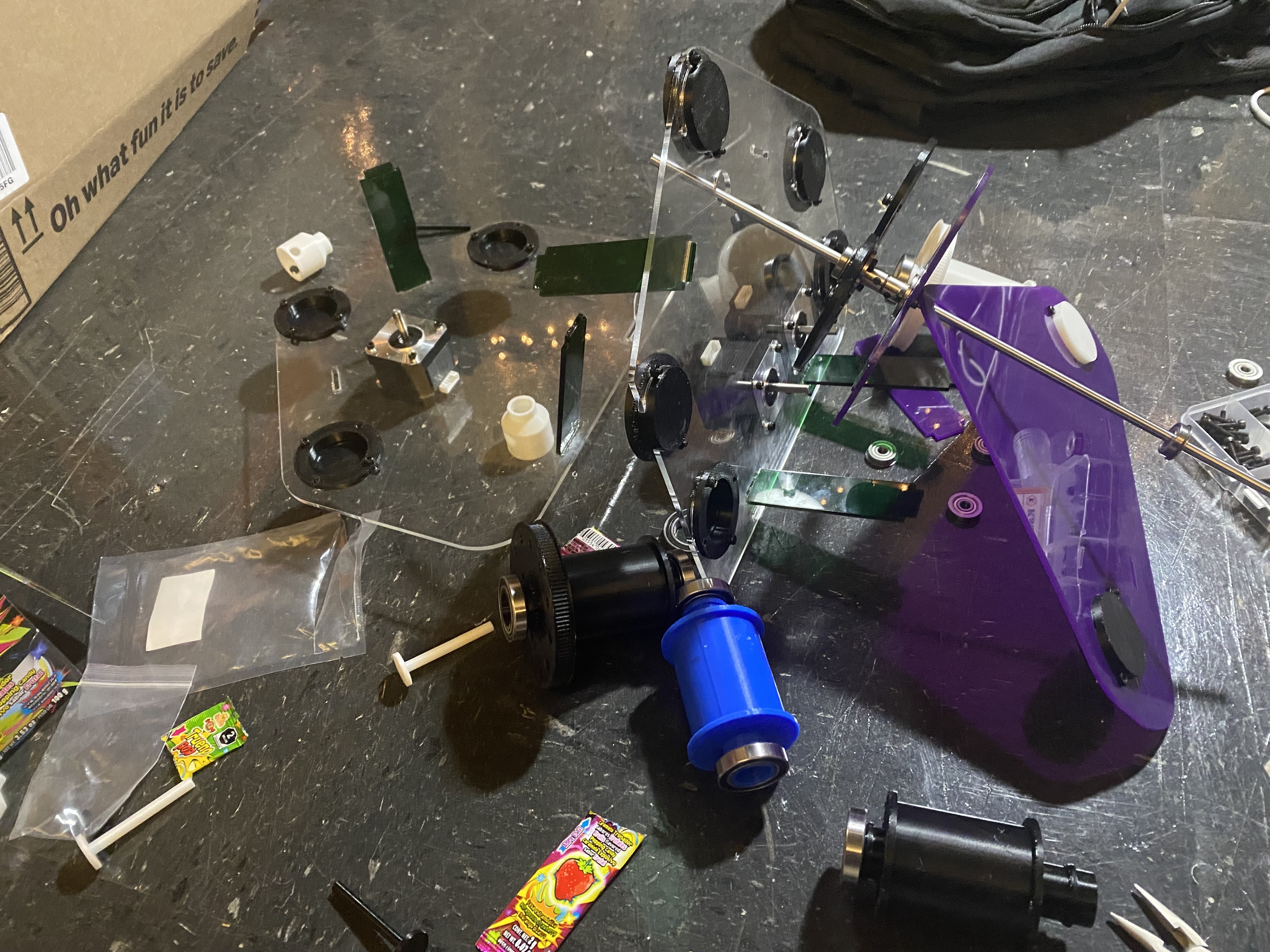
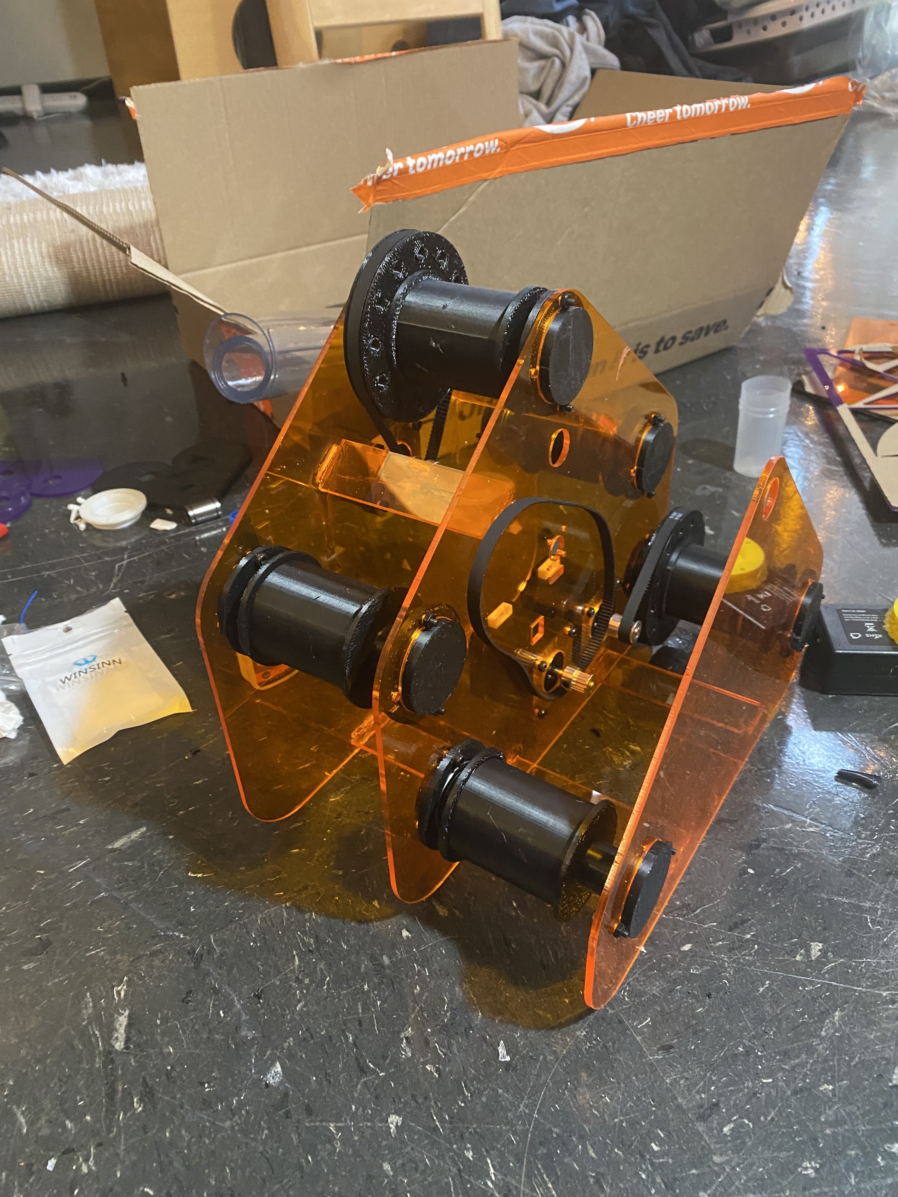
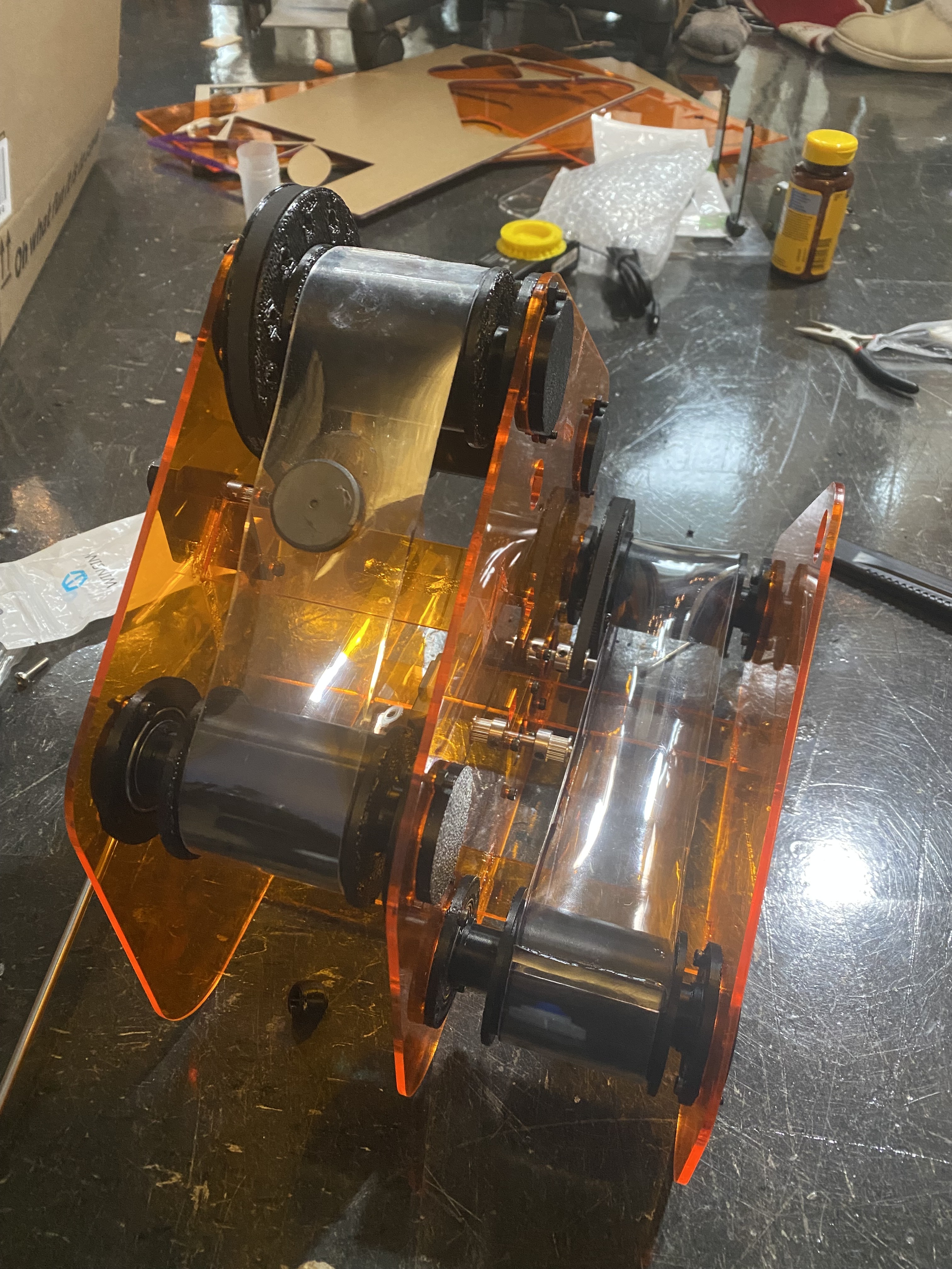
I was able to finally put all the acrylic together with all the pulleys. The next step is going to be to add the plastic which
creates the belt for the conveyour belt. I really hope this works. After that I am going to finish up the heart part and then
start with the actual integration of electronics and physical. Stay posted! I just realized i put in not one but two of my
pulleys in the opposite direction and I have no clue how to fix it without breaking everything so I guess iam going to
make the belt less wide. AHHH I was so sure I had done this correctly. Okay so I got a friend to help and the acrylic was
able to bend enough for me to pull out the roller. I also was able to cut the belt with a boxcutter and glue it on
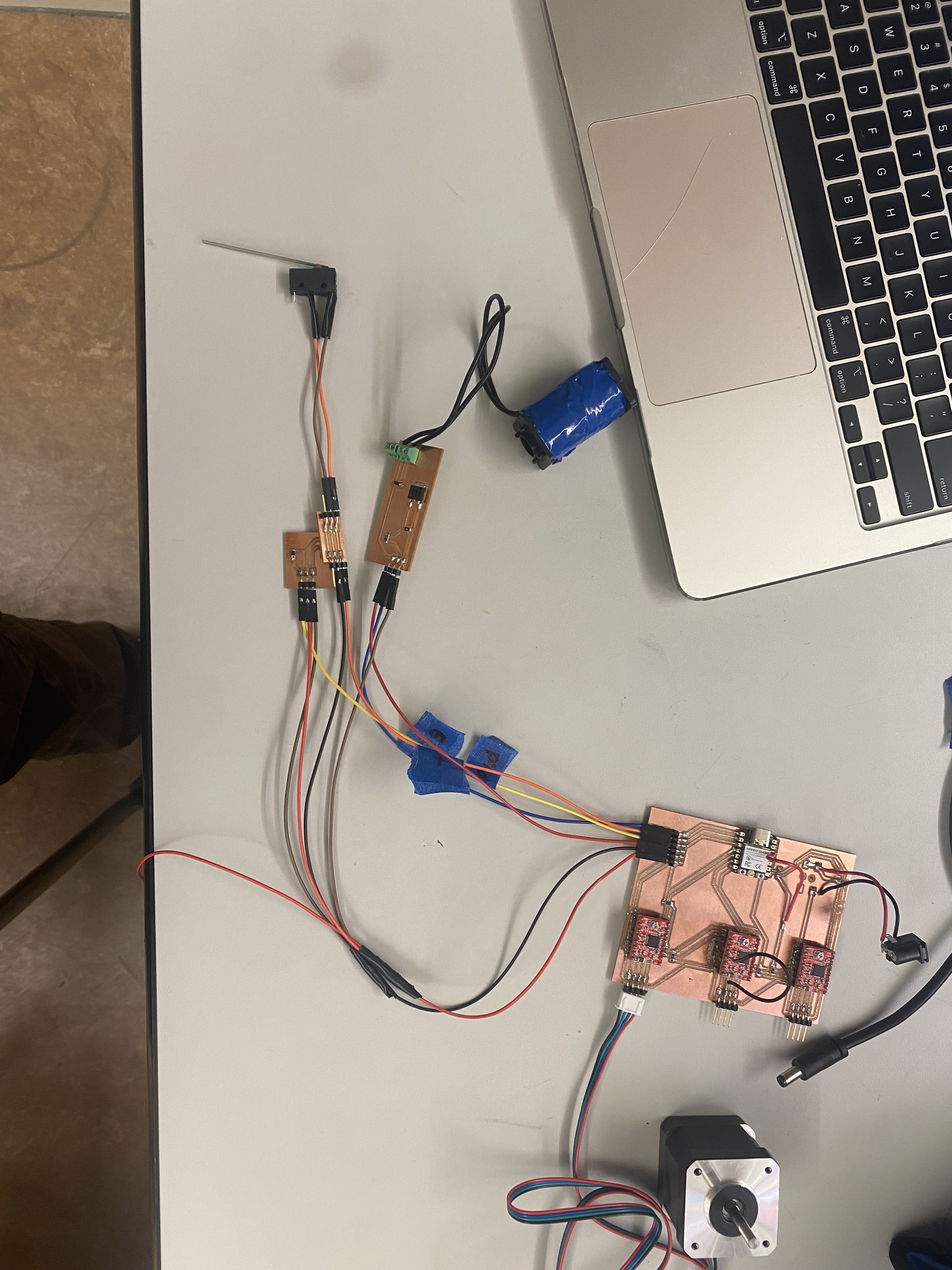
Electronics
So the first subsystem will need battery power, stepper motor, esp32c3, and a motor driver, and a limit switch. The second subsystem needs battery power, stepper motor, esp32c3, a motor driver,
phototransistor. The third subsystem needs battery power,stepper motor, esp32c3,a motor driver, and an electromagnet.
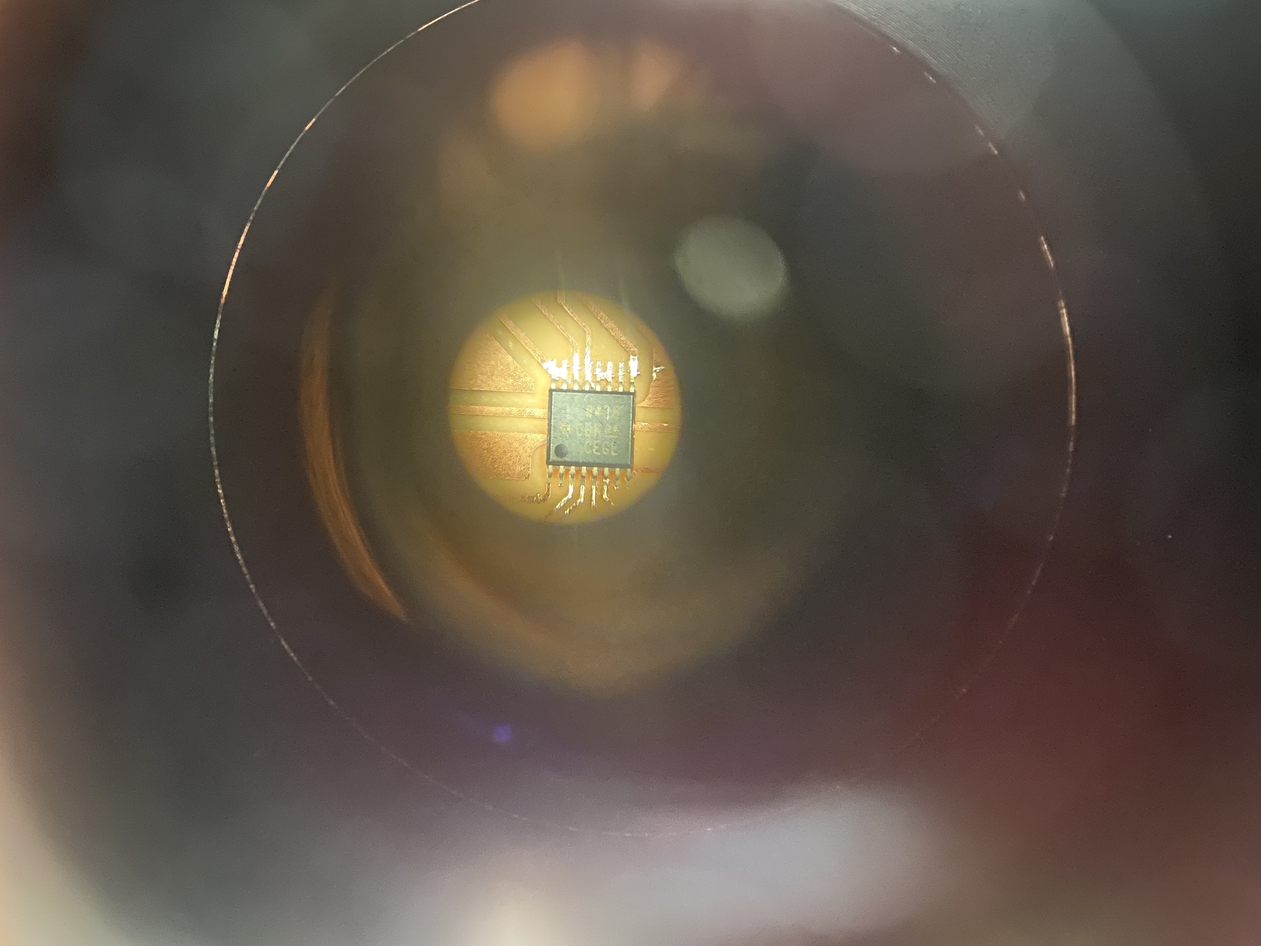
In my week3 project I worked an a4988 stepper motor driver but I am supposed to be using a DRV8428PWPR motor driver so
I hope some of the pins are the same I was able to find the TI datasheet that told me what all the pins were and I
am going to go to OH later and see if they can verify my schematic. I made all three of them and hopefully everything comes out good yay!
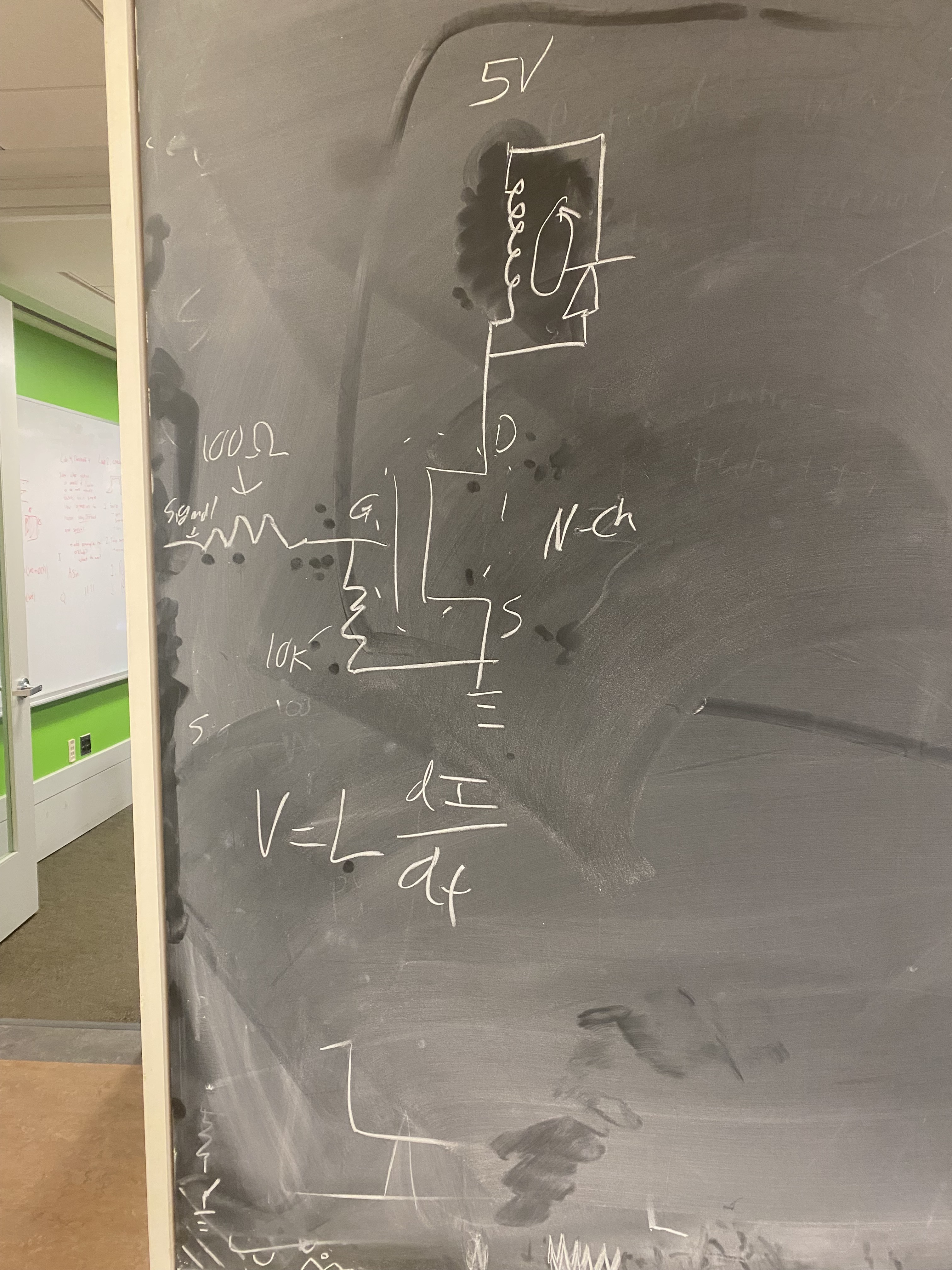
Okay so I went to speak to Anthony and woah buddy was I wrong. Just for starters the breaboarding I was doing for
my electromagnet... never going to work. There isn't enough current I have to design a PCB that uses a MOSFET in order
for it to work. Apart from all that I have to somehow figure out how to wire three stepper motors and the electromagnet
into a cable that will then be plugged in somewhere. I am more than a little bit overwhelmed and I haven't even
gotten to the coding part yet so I guess I'll keep you updated.
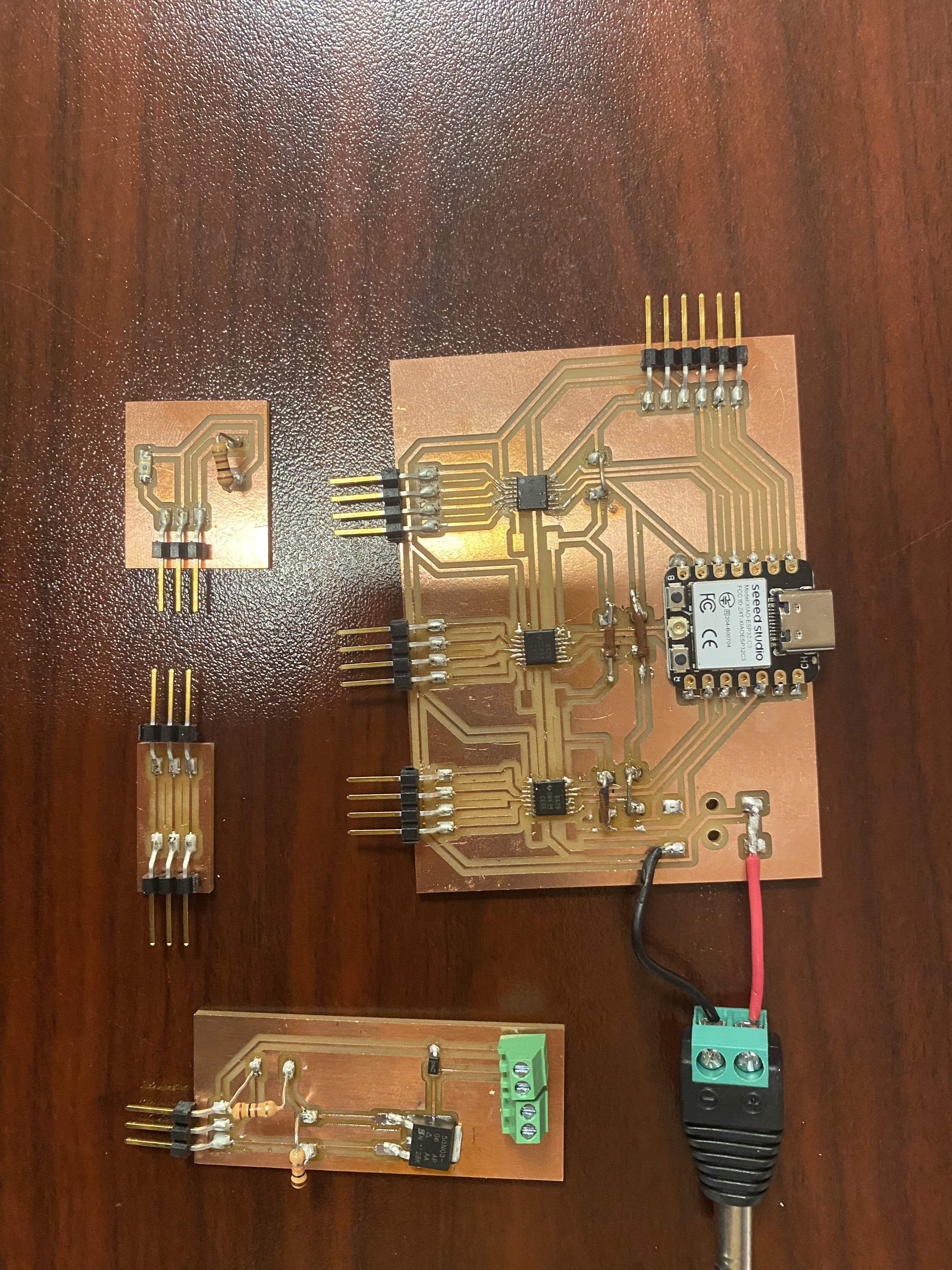
Okay so the general idea I have so far is creating three board that all connect to the same esp32c3 and control the three
motors and the electromagnet. I am not sure but then I may as well connect the limit switch and phototransistor as well
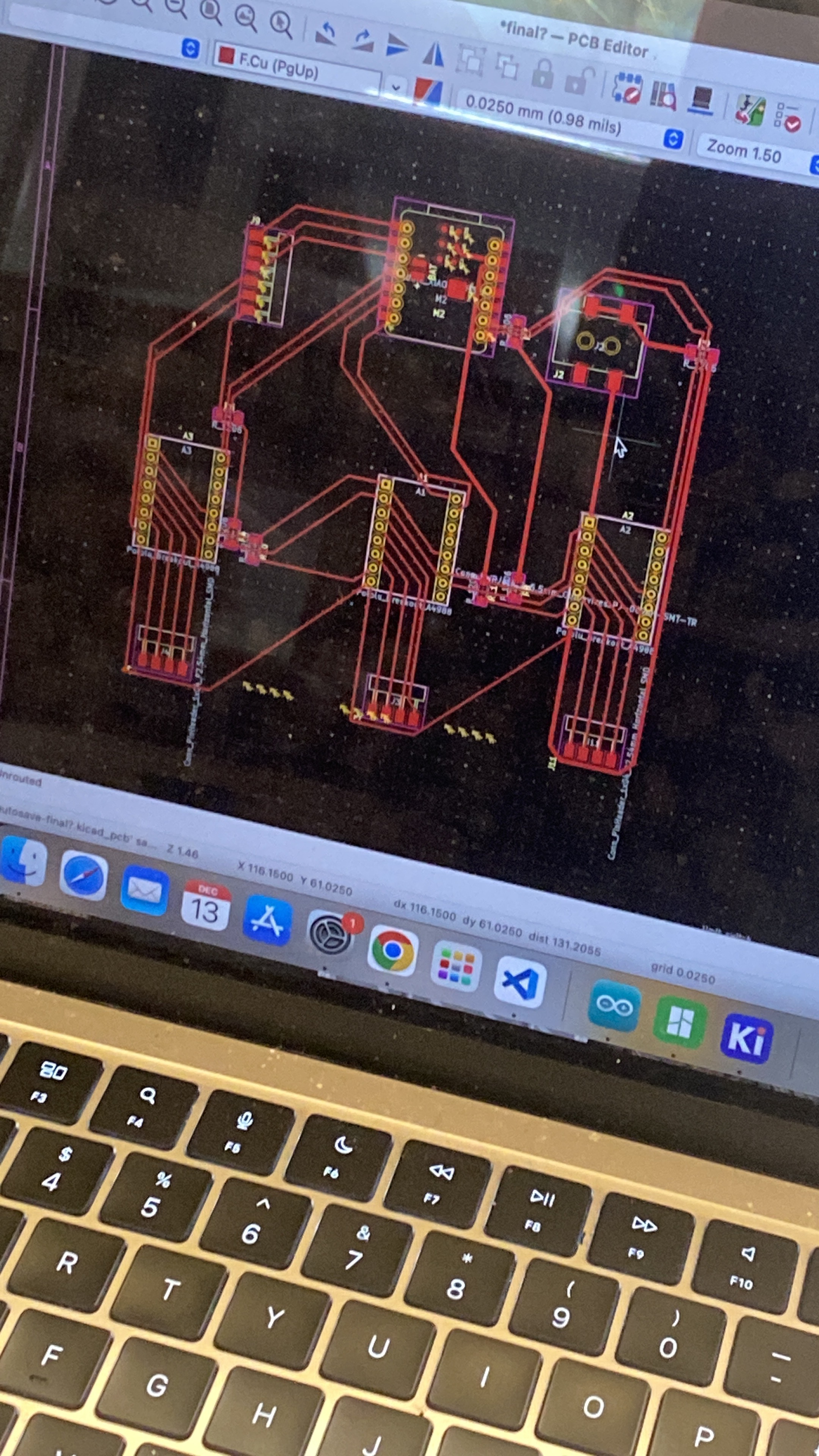
I think. I made a schematic wooooo let's see if it works.
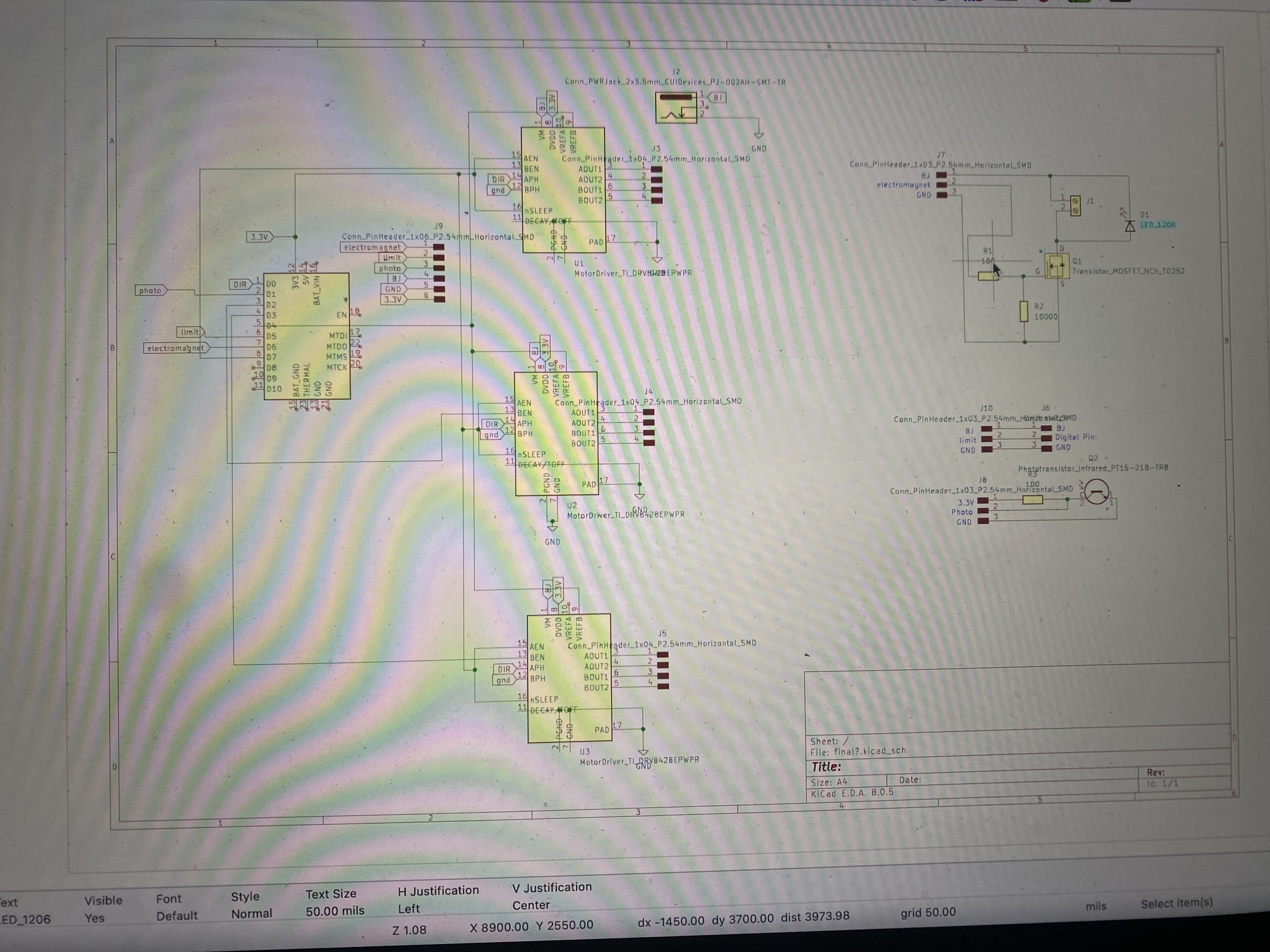
I realized that even though it is one schematic it needs to be
about four different physical board which means that I need headers to be able to connect everything together. I am a bit confused
as to how to power everything but I figured out I can just make headers that connect to each other. I checked it with anthony and
the only thing he said was to flip the A po and A neg pin to make it easier to make the schematic but apart from that it was good
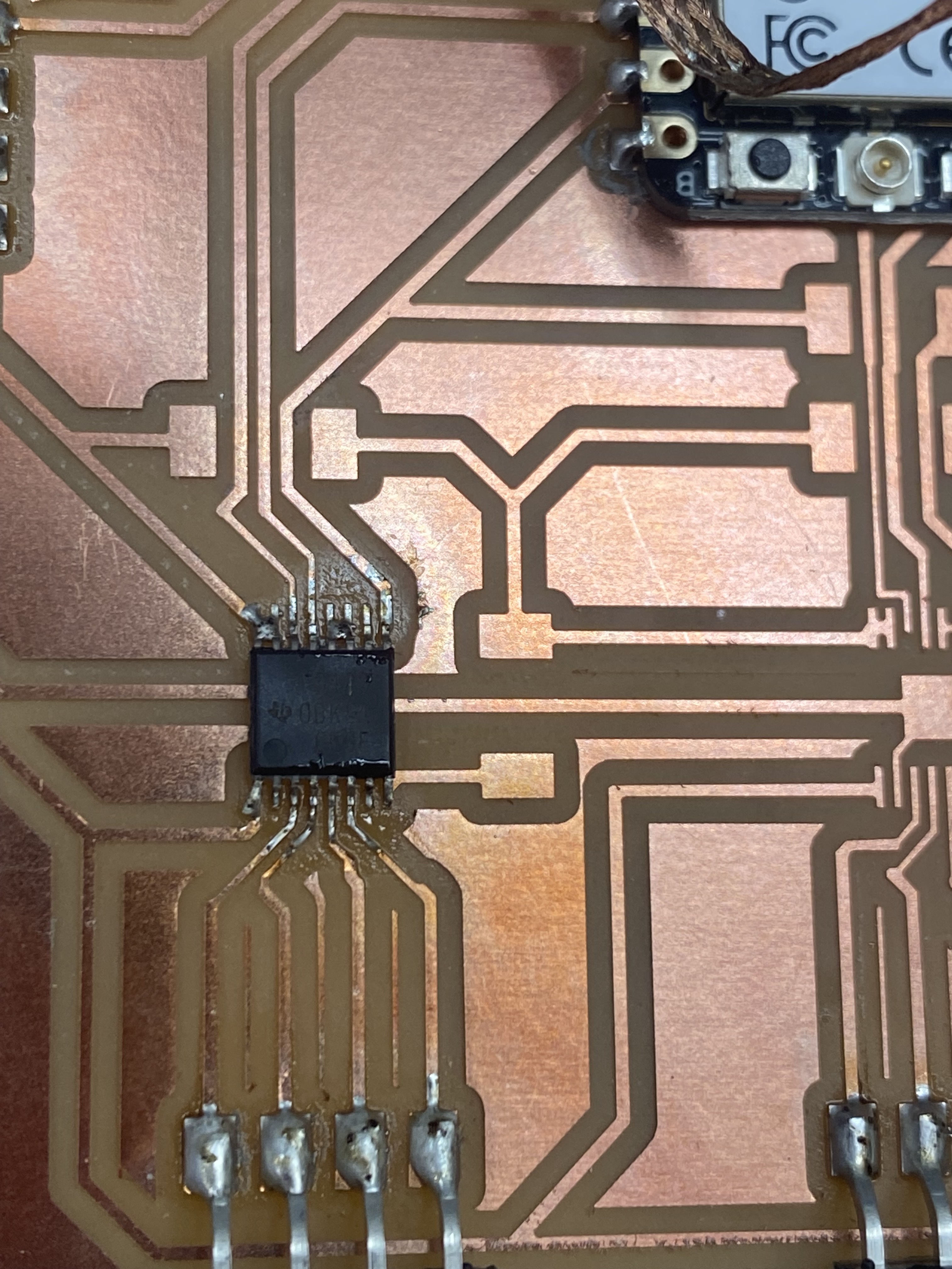
so I am excited to bring it all together. Apart from that he showed me how to change the footprints of the drivers because they are
too close together and the tool would ruin the traces of the driver so instead of having pads of 0.4 they now have pads of 0.25 you have to
go update in footprint editor -> properties -> and then change one pad and set that as defualt and update the rest of them. I was able to do
that and now I am adding in other traces but it seems really difficult Anthony had previously mentioned that I can jump traces uses a 0 Ohm
resistor soooo i think I am going to try that in with 3.3V tags so I can just add them in wherever I need them to be. I need to be
a bit more tactial with my connections to pins making sure that I can avoid as much crossing over as possible so I can make sure
everything gets to each other
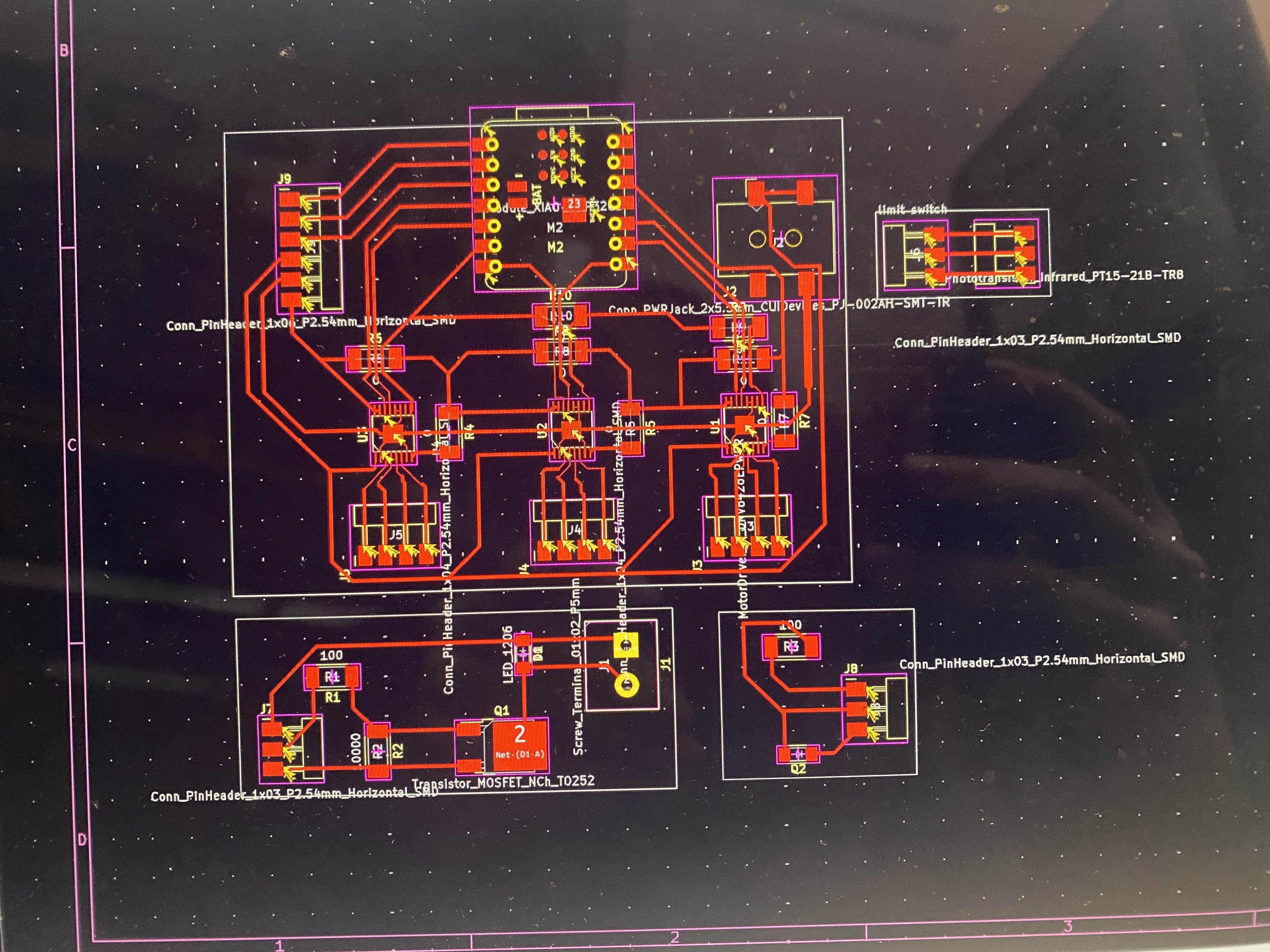
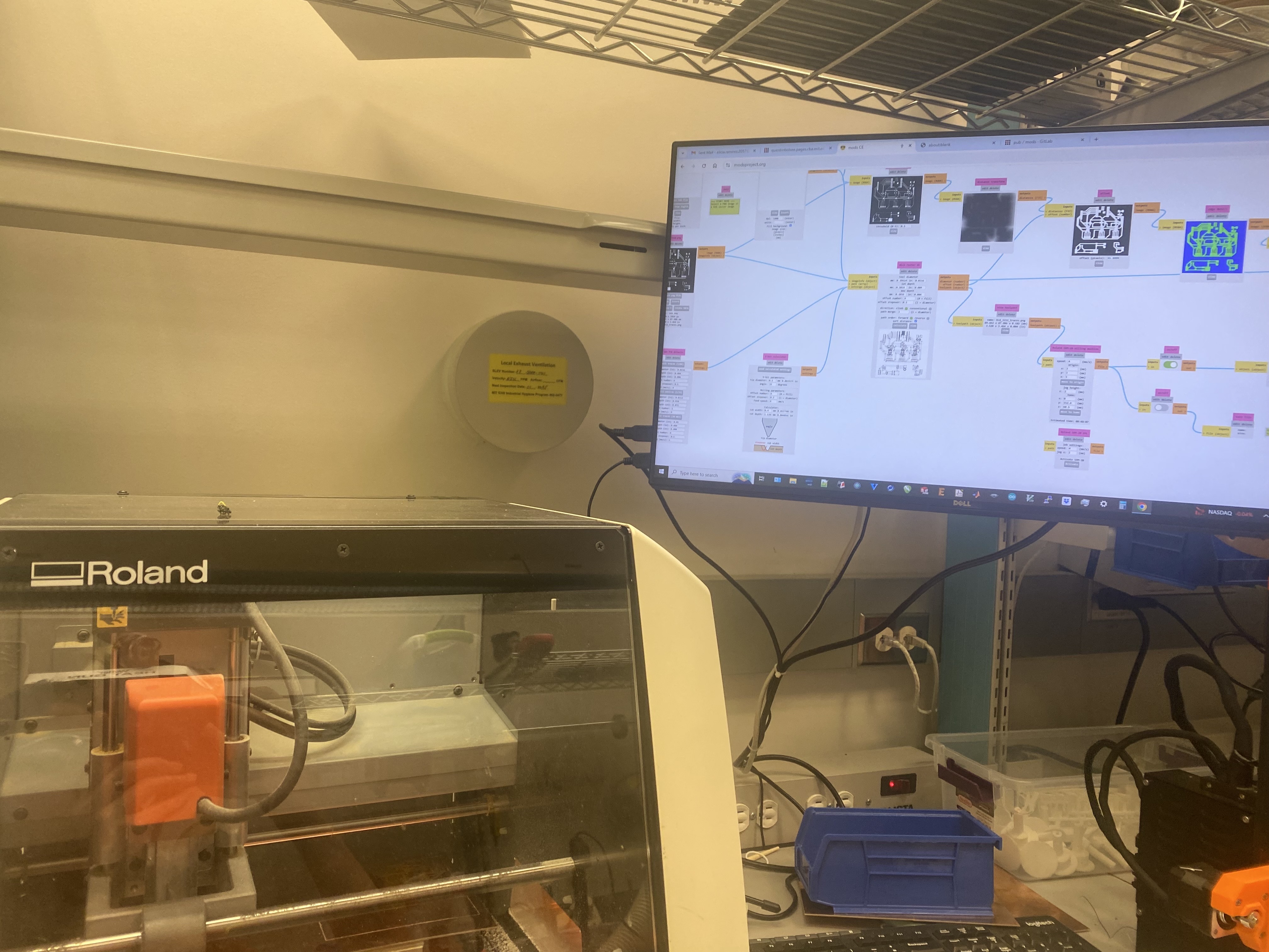
The PCB is gorgeous and I am attempting to mill it right now but already a number of things have gone wrong: theres no more double
sided tape, my copper plate is bent, and I am tired.
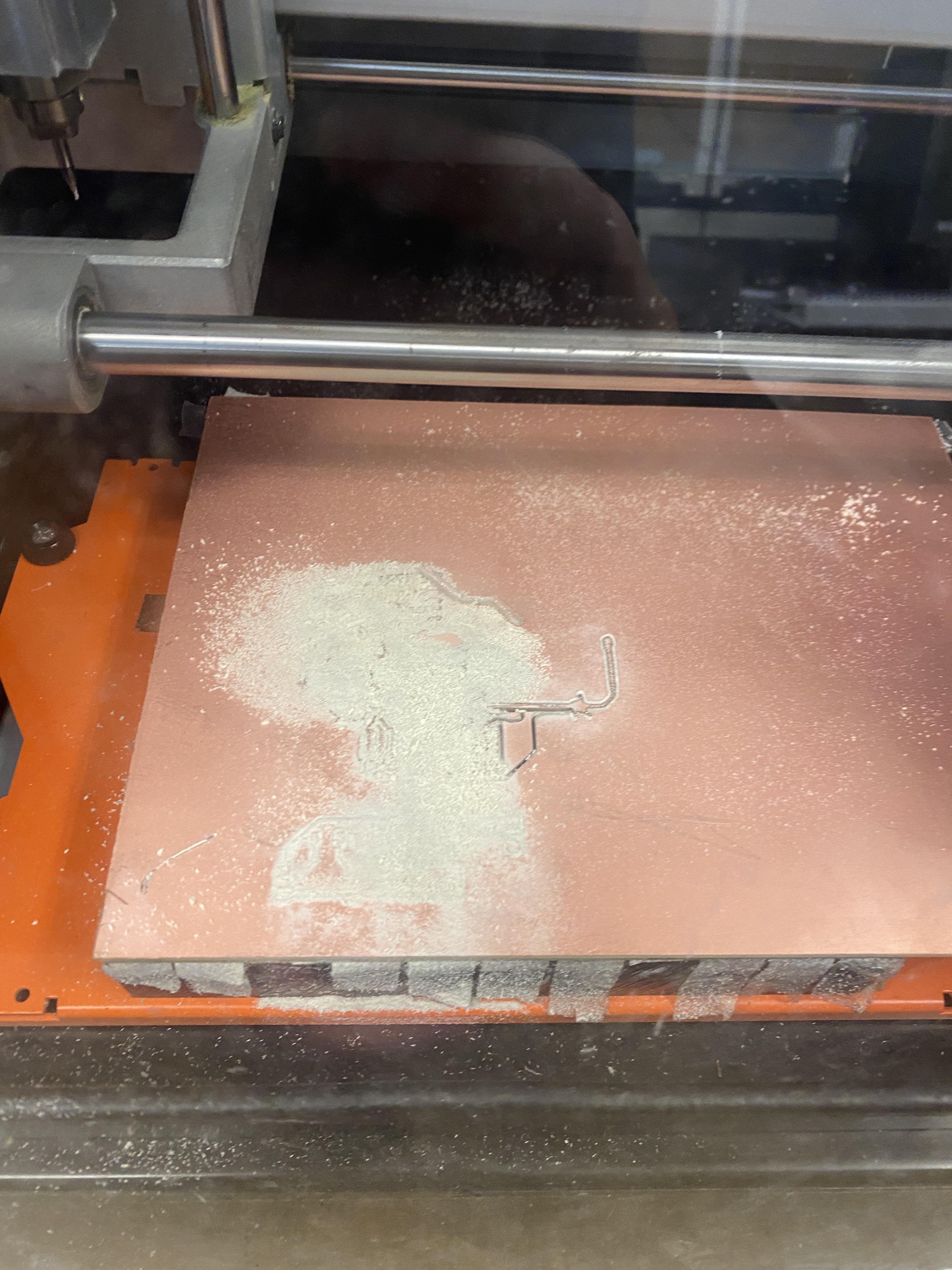
Let's see if this works. It did not work it cut all the way thorugh the traces and
it just was not clean so I decided to head over to EDS. It was a bit scary at first because they use different mods and I was really worried
I was going to mess it up but I think I was able to get it and it is currently cutting so hopefully everything will be okay. yay!
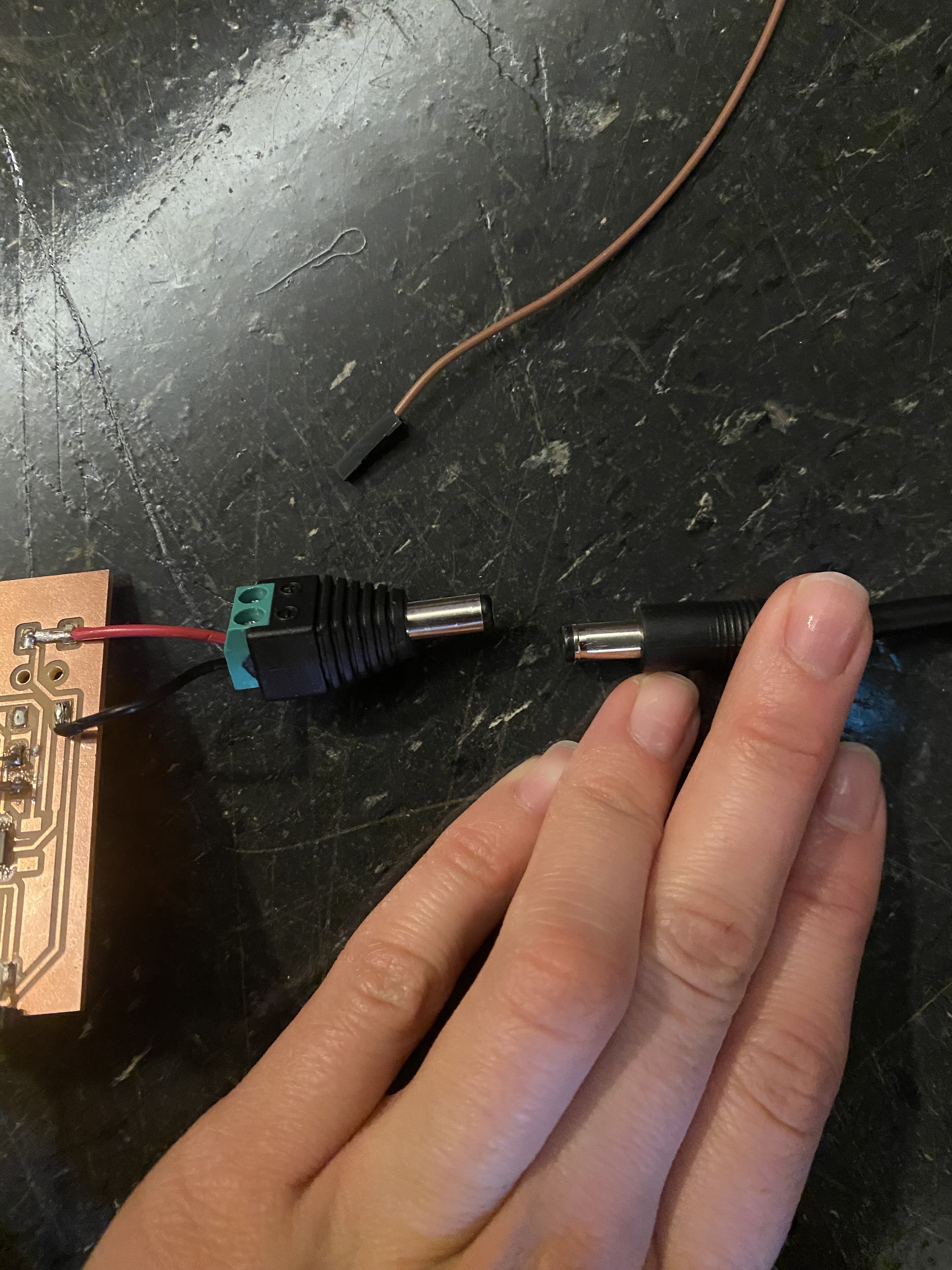
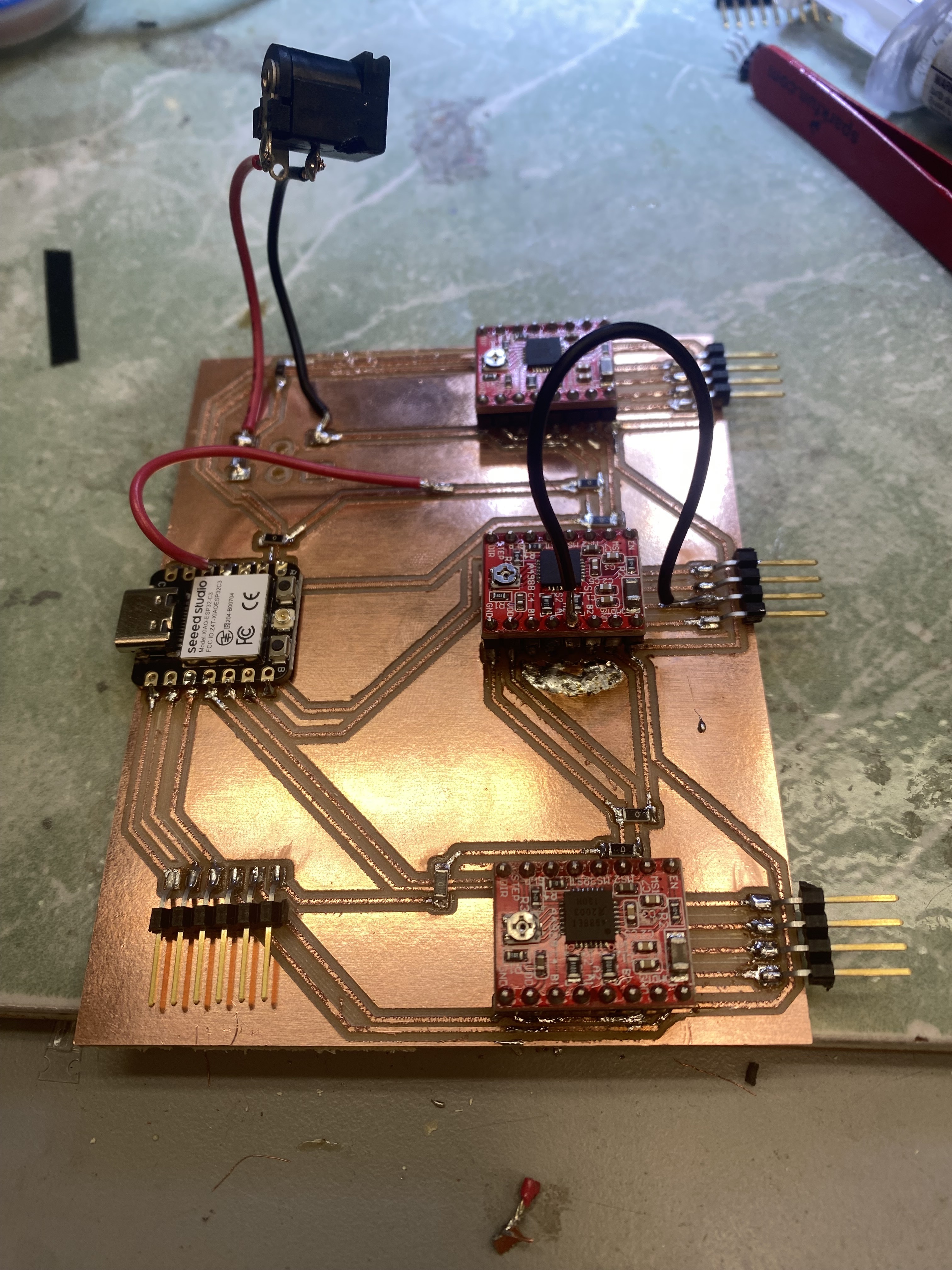
I ended up cutting all the PCB boards and soldering them yesterday. It was a very gruelling eight hours. Thankfully everything seemed
to come out okay apart from the fact that I soldered on another male instead of a female for my power adapter.
The mini soldering was SO
cool because it was very intense and precise and I didn't know I had that steady of a hand.
Overall all it was a super fun process.
One of the main things that went wrong is that I got the wrong footprint for all my resistors so instead of a 1206 I got a 1210 which
is significantly bigger and not something we have so I had to solder on not surface mount wires and resistors to do the same thing.
Today I am going back in to test it yayy. Woo so I broke the copper trace for my power isn't that exciting meaning I need to remill
the entireity of my board and pray that the only thing wrong is that the trace broke. But I am not sure that is the only problem because I
did some jank connecting and connected it to power and the seeed xiao didn't have it's little red light turn on so I am concerned and a half.
I may as well remill my other boards becauseeee the resistor stuff is wrong anyway. But technicaly since they all end at three terminals
I have a board from a past week that I can start coding with to make sure everything technically works. Okay so I spoke to Sam and apparently
I'm kinda dumb (he didn't say that) I was all worried that the xiao wasn't turning on but apparently I was supposed to be powering that on
with a usb C cable anyway apart from the barell jack so we did a small test to find which pin was ground and which was power and I fixed it.
I also updated the PCB to have the right footprints for the resistors andddd I think that was most of it. I am currently milling and let's
see if all the traces come out nicely. Hopefully they will. Okay I finished milling and soldering there was one small accident with the
power trace again buttt I think I was able to pull it off because only half of it snapped. Let's try something super simple making the motor move
so unfortunate update I took a break because something went terribly wrong. I think I shorted something because something sparked and smoked
and I had to do a bunch of wires that jump the issues with my traces and I forgot to actually connect the grounds to each other.
Hey hey I am back and we are creating a new PCB wooo isn't that sooo much fun. Yes yes it is. I am switching the driver from a DRV8428
to an A4988 so that means I have to redo my schematic and then also redo the actual wiring, milling, and soldering. Hopefully however
I will be able to get some type of moving prototype by the end of tonight.
THE ELECTROMAGNET ALMOST WORKS. It turns on and off
like it is supposed to the only thing is that it doesnt necessarily fall however after two layers of acrylic it does work well so
I am going to add it in and I think it should overall work through one pulley and a layer of acrylic but I guess we will just have
to find out.
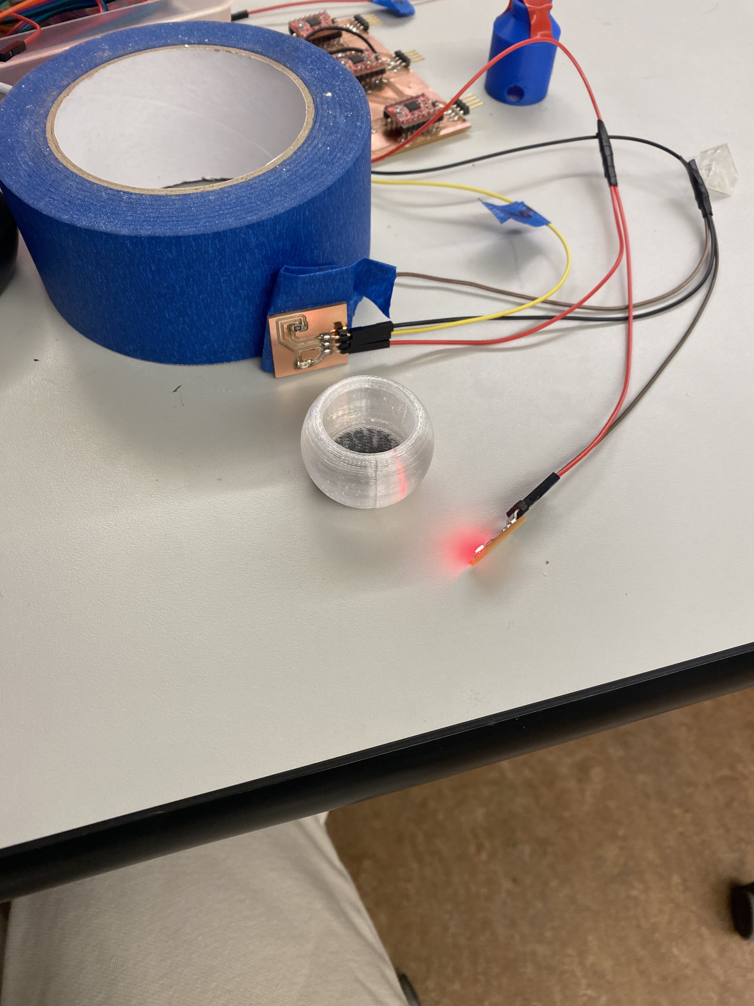
Now I am going to move on to the phototransistor and see if that is going to work. I am having a few small issues the values
that I am reading off the phototransistor seem to be basically random and don't go to 0 or the max when you block it. I fixed it! I had the
pin and the power switched the pin needs to go straight into the phototransistor and then merge into the power.
Okay today a lot went wrong which I should have anticipated. The first issue was with my board the holes were too small for the
driver so I had to drill them out by hand and then pray that the traces stayed in tact. After that it was super difficult to solder on
the driver itself because all the points were so close to each other and at first the tip of my iron was wayyy too fat. There were
some points that I could not get because I simply don't have that experience yet so I had to ask anthony for help unbridging some of
my shorts (I only had three and its because of how the PCB was cut so it came out kind burry and the solder kept sticking to that).
After that stuff still didn't turn on so I freaked out but apparently I just messed up and forgot to actually connect 3.3V to the esp32c3
So I cut a wire across and then I also had a trace that broke with the motor driver that I also jumped in the second motor. After those
fixes I had to give it a different power supply that was higher than 5V to actually be able to power the motors. But now at least one turns on!!
That means that my next step is to see if I can get it to stop when either the limit switch is pressed or when the phototransistor senses
something in front of it. This is so exciting!! I also have to great a BJ and GND wire that splits into three for my three subsystems.
I split the wires and am testing everything plugged in running at different times. I am a little bit confused because the electromagnet
was not working and I didn't change anything and suddenly it was working. I am having some issues with the limit switch as well. For some reason
it is fluctuating between on and off without me pressing anything. Okay so the issue is that I was missing a pullup resistor so I needed to add that
to the definition of the pinMode input so now that that is there it works yayyy. I am going to do some basic integration which is if the
limit switch is not pressed move the motor, and then if the phototransistor is blocked turn on the electromagnet. I was having a lot of
issues with the phototransistor so I remade the board and I made an extra board with an LED to create a constant light source.
Code
My first step on the code is to create a webserver that allows me to click on different colors and takes me to a different page. This should be fairly simple with the previous background I have from a past week. So let's get right into it. I started by making a few different pages based on different colors and I am going to have an intermediate page for when the container needs to be moved. Okay so far so good I have the general site set up it is a bit ugly but hey the buttons work and they take you to the right page so far.
Integration
I am currently putting together the physical and the electrical. So far it has been a bit bumpy. I had to add
hot glue to the bottom of the belts so that they would grip the rollers and turn when the motor turns. I had
an issue when I tried to make all the motors move at the same time (they didn't) but I got one working by itself
I am still currently having issues with the phototransistor and even with the LED shining. However I was able to
attach (the wrong limit switch on) so I have to go solder that. After so so so much time I was able to
make the phototransistor work with help from anthony we changed it to a cool white LED to make it brighter
and now it can actually sense when it is blocked versus when it is not meaning that the next step
is to connect the motor. IT finally finally connected and was able to stop when it ran into the container with the
phototransistor. Okay so it is tuesday morning I gave up last night because I had reached a different level of
frustration but today we are all fresh. Last night I was having a lot of issues with actually uploading
my code to the xiao which was not something I could really control but today I am able to handle those problems
with a more level head. The webserver is working so far we have the limit switch and the phototransistor working
I just need to make sure to callibrate the phototransistor to wherever I am by printing the values checking to see
what the values are when its blocked and then adjusting the while loop in the code. I am currently working on
making the motor for the heart move only a certain amount of degrees which is something I had previously
programmed but for some reason the way I am calling the variables is raising an error. Tangent I started
getting a new error with the "watchdog" which basically said I was running the while loop for too long without
it actually leading to anything so I had to google a lot and find the correct library and then
reset the watchdog for every iteration of the while loop so that it would not time out before.