Documentation
Group Assignment
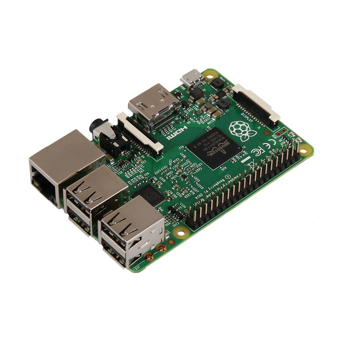
We all gathered after recitation to talk about the difference between microcontroller and microprocessors and
everything we had been learning. The difference between a microcontroller and microprocessor is that microcontrollers
are "small computers that on a single chip" and are often used in objects that have low power consumption while
microprocessors are more complex and are used in computers and other hightech things. For example seeed xiaos and arduino
are microprocessors while the Raspberry Pi is a microcontroller.
I think for all the applications of this class I will
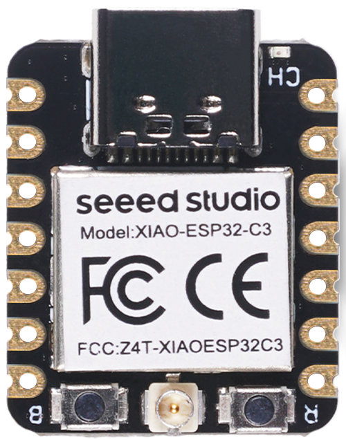
only be using microcontrollers. One thing I am confused by is that the ESP32 seems to be a chip and a board at the same
time so I don't know if it is a microchip or a microcontroller or if there is another name for it. I have personally been
exposed to arduinos and raspberry pis and over the summer I attempted to work with a Seeed Xiao ESP32s3 but I was not
able to make it work. This time it WILL be different. The main highlights of the ESP32 Seeed Xiao c3 and s3 is that you
can make wifi on them and they also have bluetooth. I am looking forward to getting to use these features later on in the
course.
The Plan
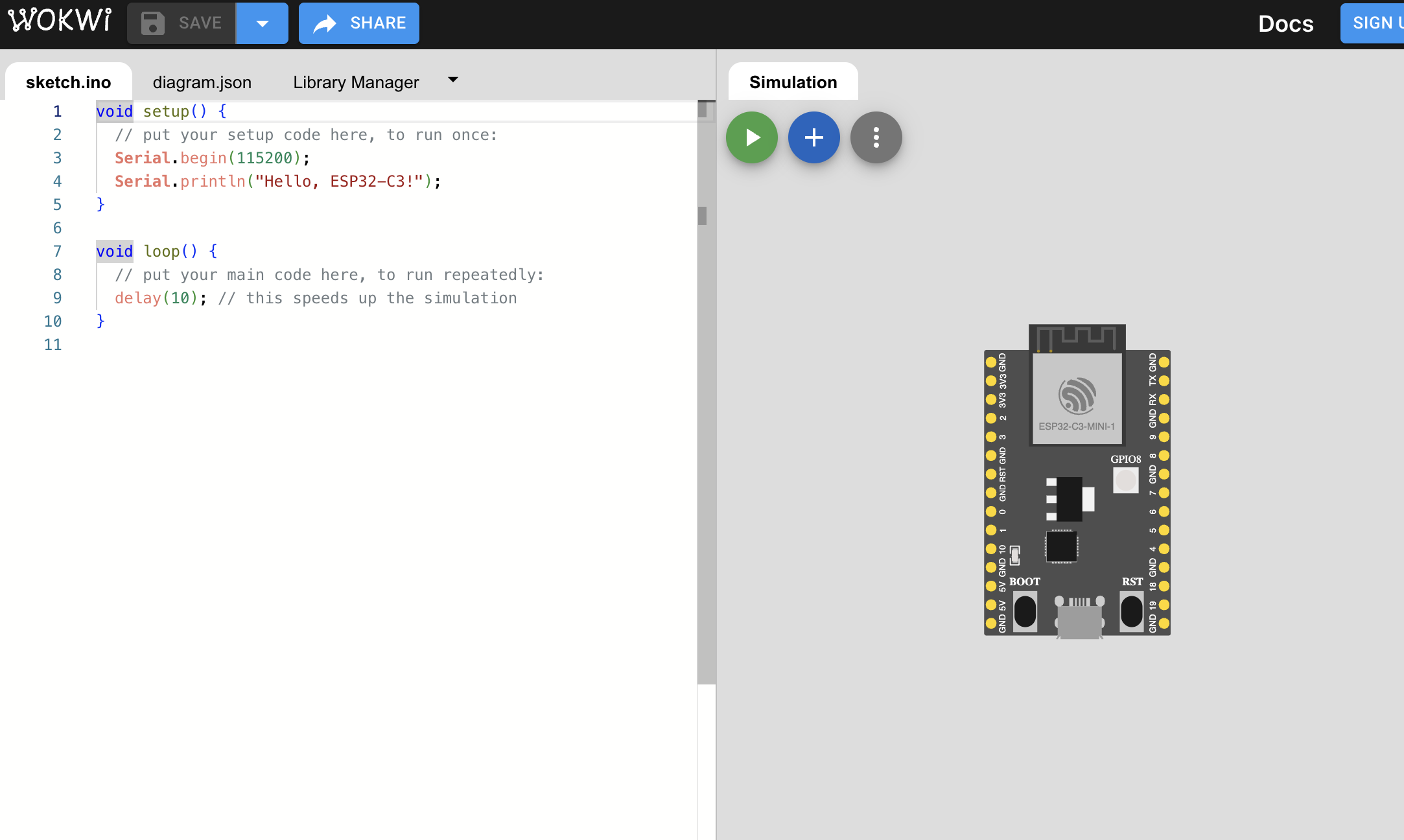
We were given two different ways to simulate and code one is WOKWI and the other is AVR8js. I like how simple the WOKWI
looks so I am going to work with that.
I really want to realte this to my final project so I am going to be working on the ESP32C3
which has all the capabilities I need including wifi. In part of my project I have one of my containers hit the limit switch and
I want to work on making a limit switch signal something else which maybe in this case will be either an LED or a servo
depending on what WOKWI has available. So it seems that neither of the two have a limit switch available which means
I need to change my plans a little bit. Instead I am going to have a button that should turn the stepper motor on.
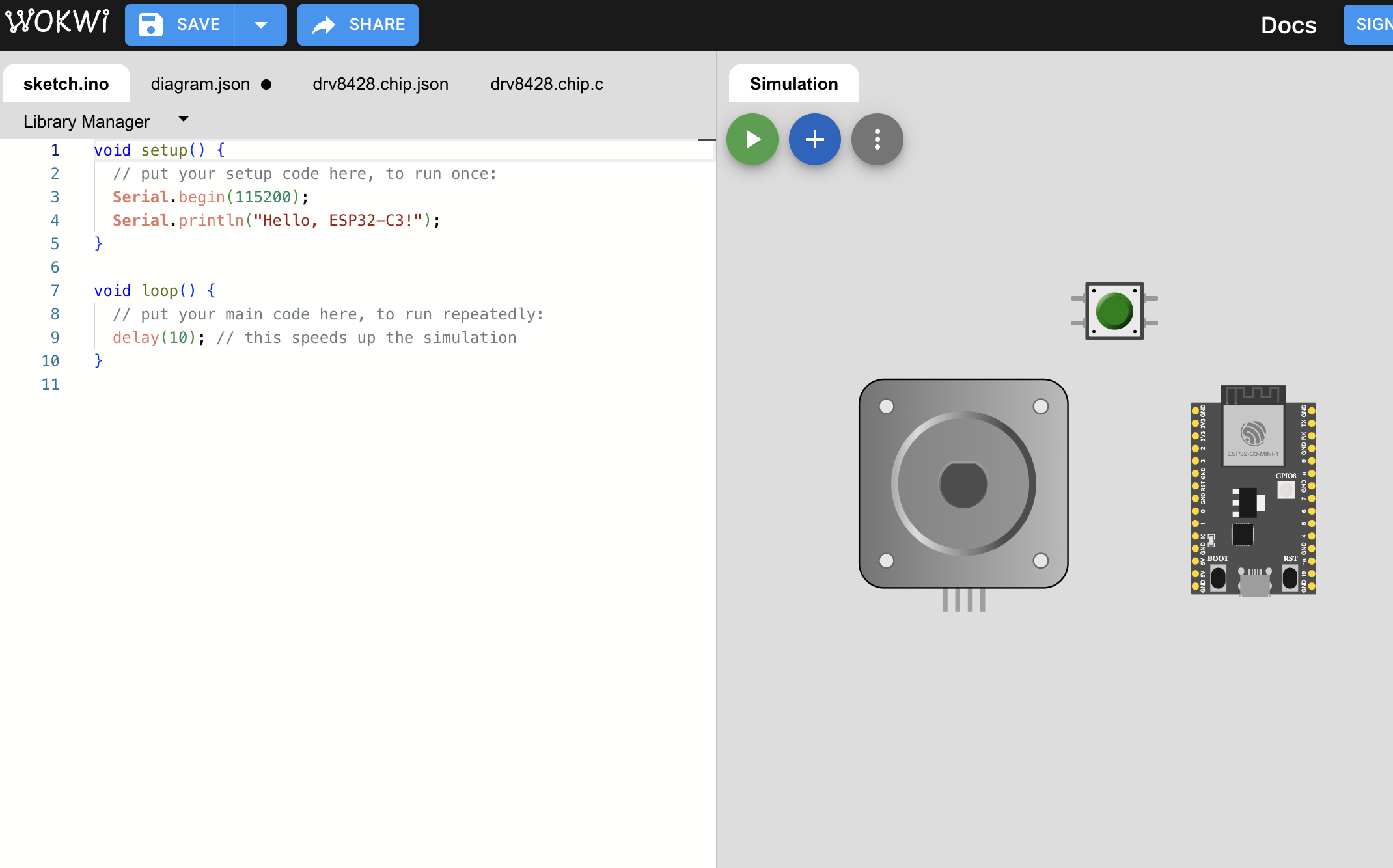
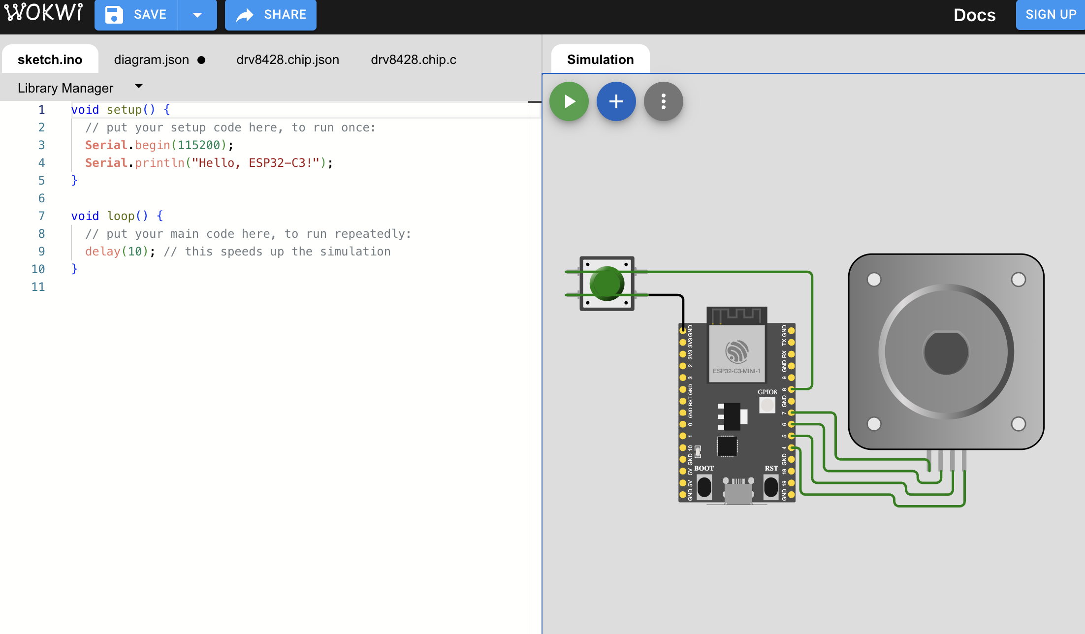
Wiring a Stepper motor
For the final project I intend on using brushless stepper motor what this means is that the motors is controlled by
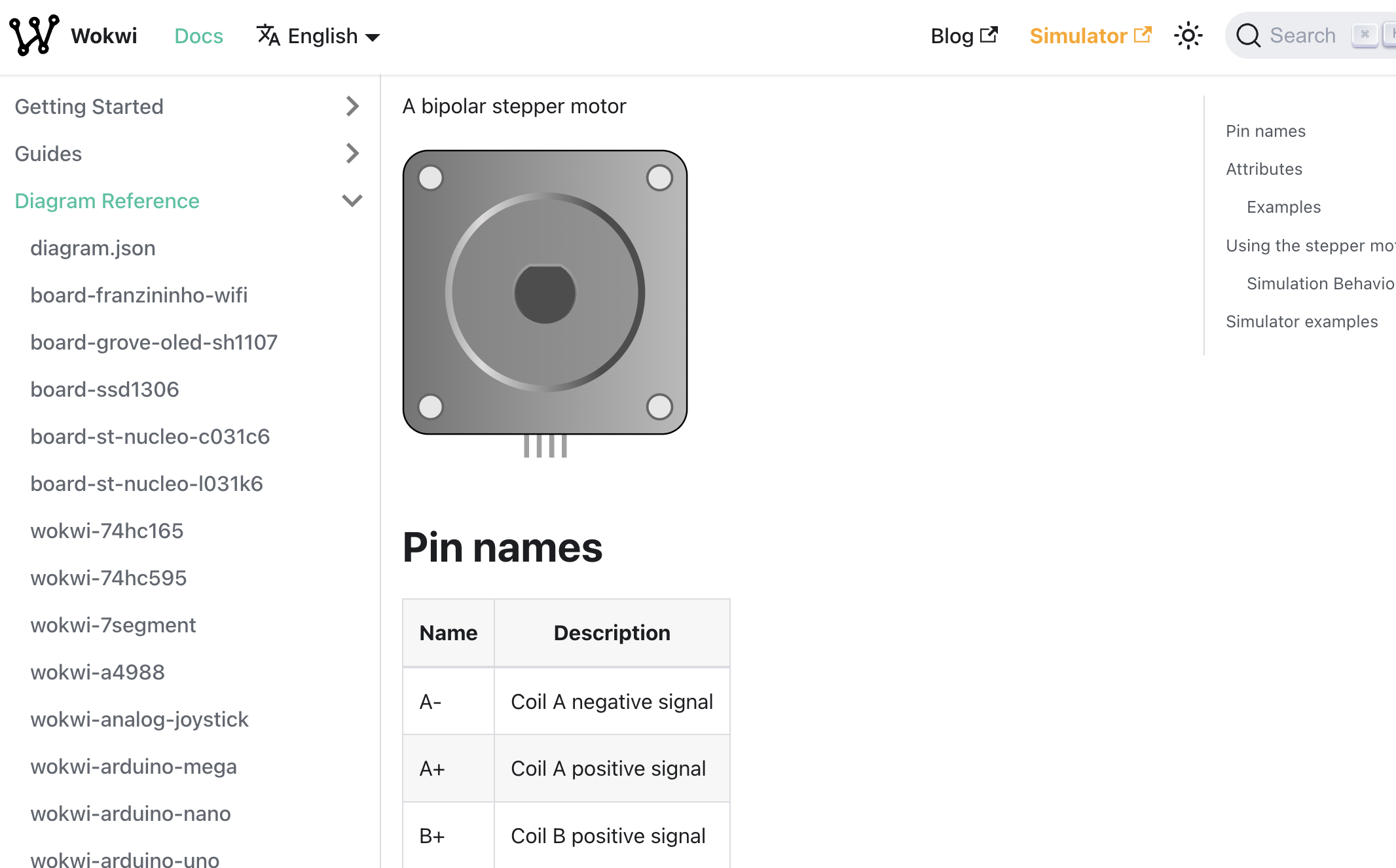
magnetic coils and changing the inputs changes the movement. Stepper motors have steps, wow I know. There are 200
steps in a revolution meaning it moves about 1.8 degrees per step. You can also half step if you want to be more
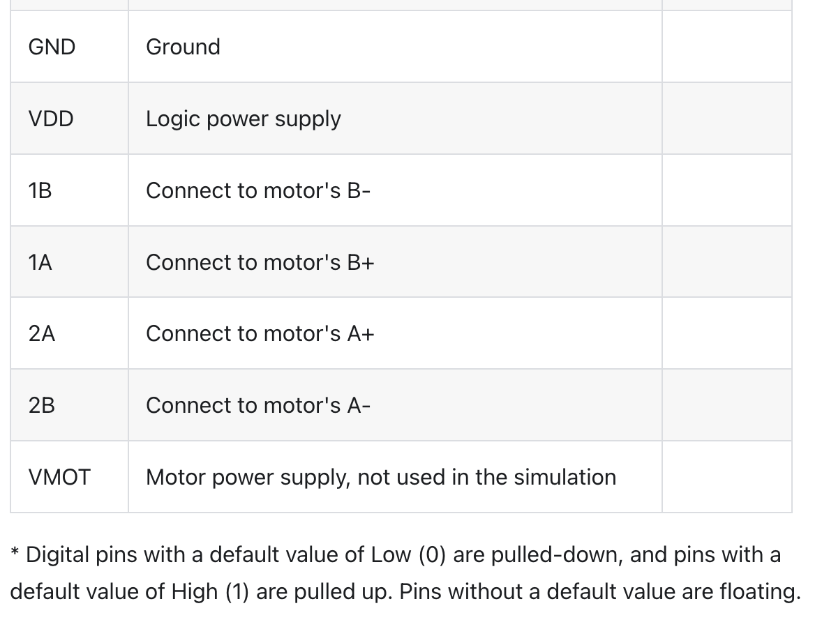
precise which is 0.9 degrees per step and 400 steps. The pinout for a bipolar stepper motor is: Coil A negative signal,
Coil A positive Signal, Coil B positive Signal, and Coil B Negative Signal.
I assume this means that they will each be
connected to a negative pin since you cannot connect them to ground or power and be able to control them.
#image of pinout and wiring
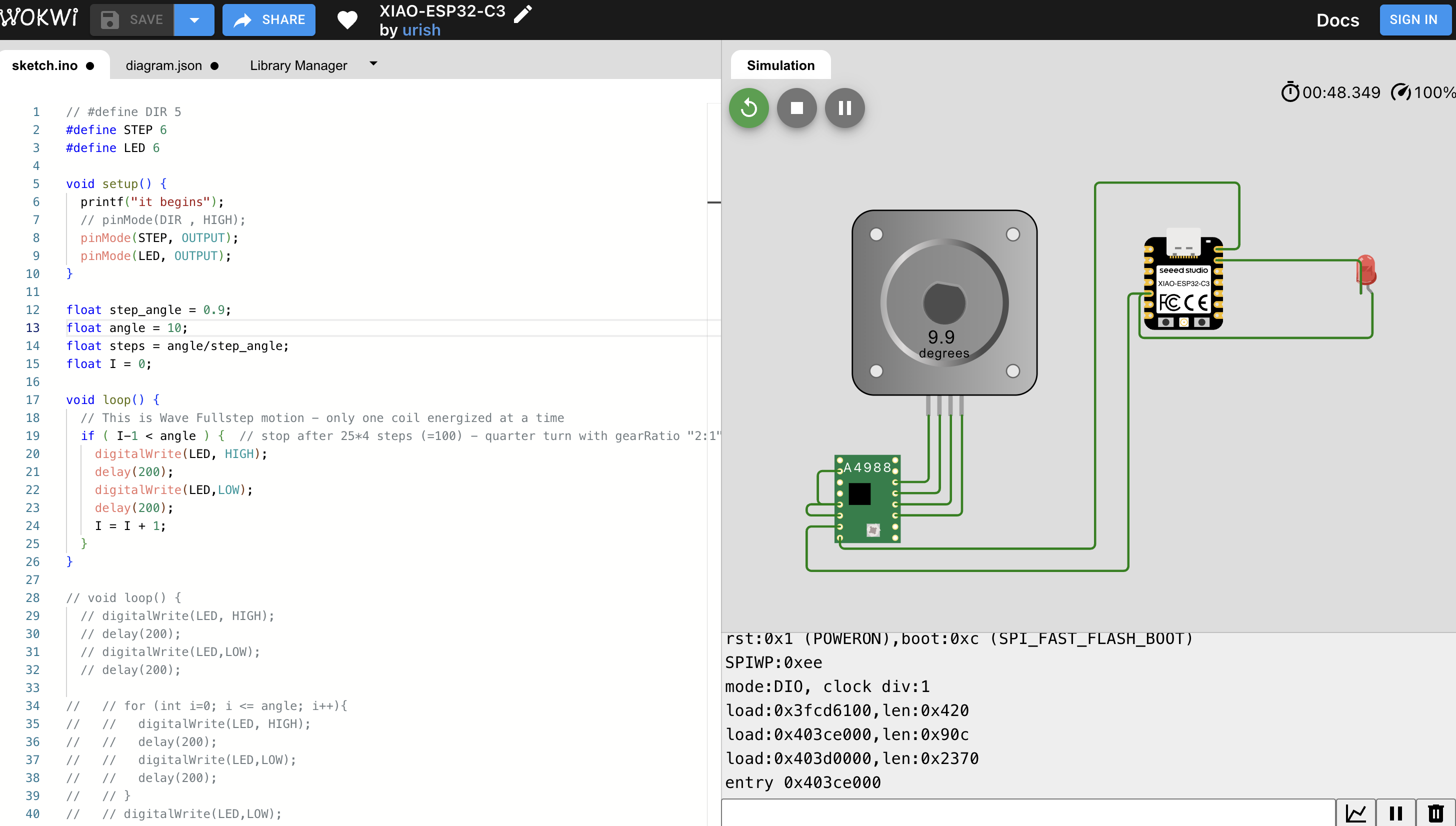
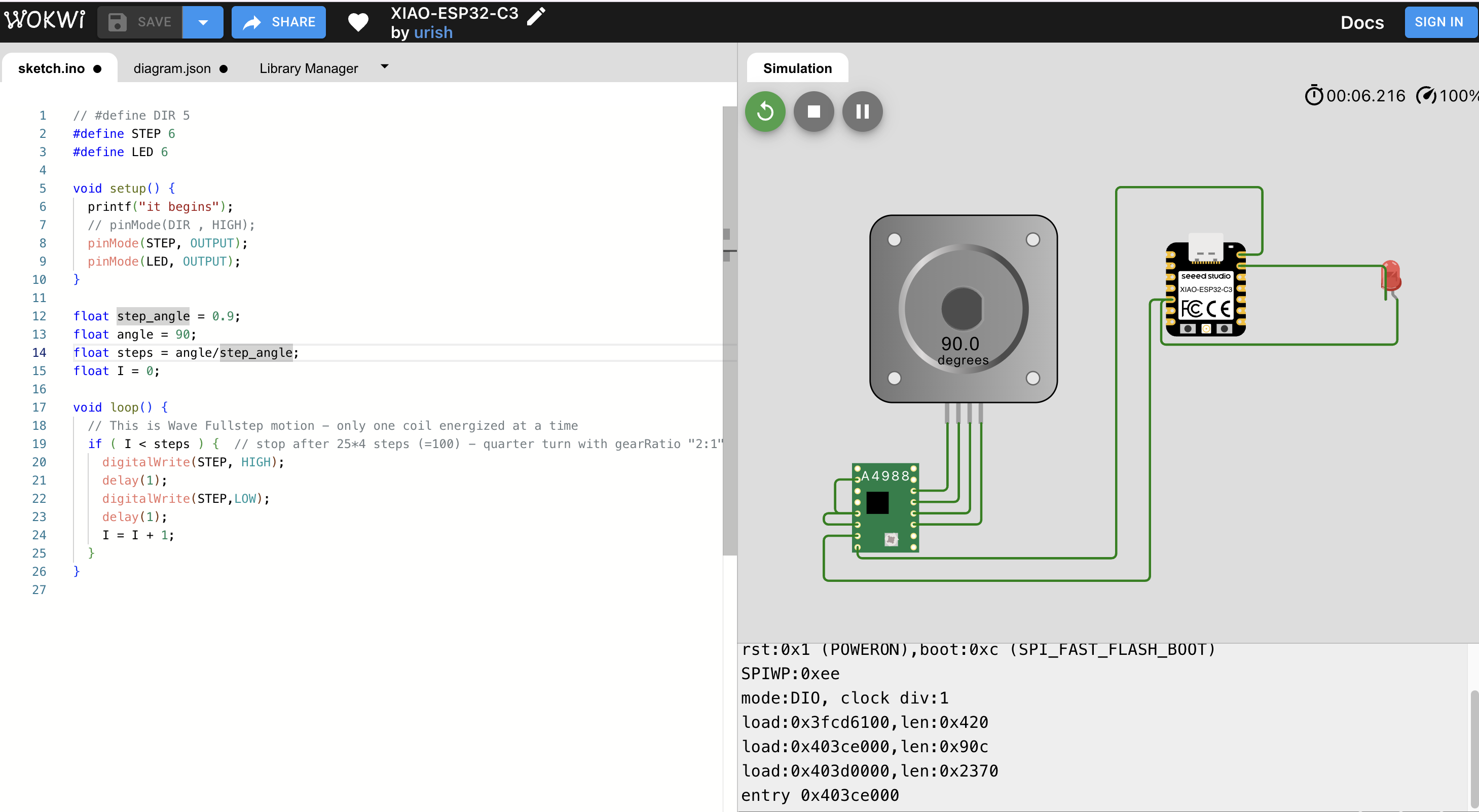
Coding the Motor
Now that the motor is succesfully wired (I hope) the next step is to figure out the coding aspect. I had previously
spoken to Anthony and he mentioned that I could use a DRV8428 to actually be able to control the stepper motor
but that I could also do something similar to servos where I feed it certain signals. I found a tutorial on WOKWI
that shows how to do the later and they also don't have the DRV8428 chip on here so I think I'm going to try the
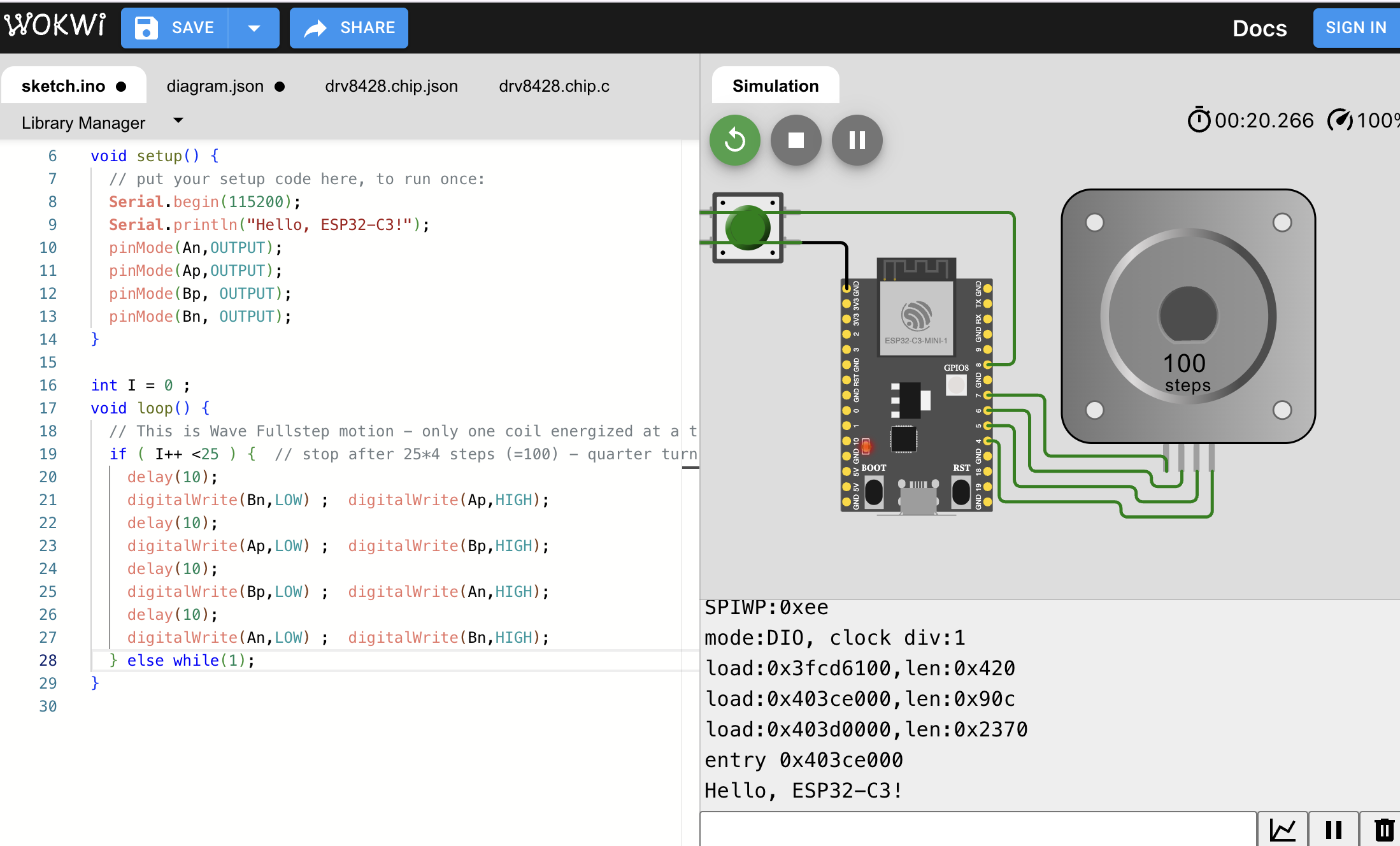
high and low approach. The first step is #define the motor pins and where they are connected to. The next step is to
set all the pins as outputs since they are motors. Then there is more code that to be honest I don't really understand.
It says that it is "Wave fullstep motion because only one coild is energized at a time". It was able to move 100 steps
but I am not sure I would be able to replicate it to move some other amount. Ok so apparently the amount of steps it
moves is the I limit*4 so to move 100 the I is 25 but to move 200 the I is 50. I am curious to see how I can do multiple rotations
would I be able to make I bigger? YESSS I CAN. I set I to 100 and was able to move 400 steps. Now I think I can change it a bit
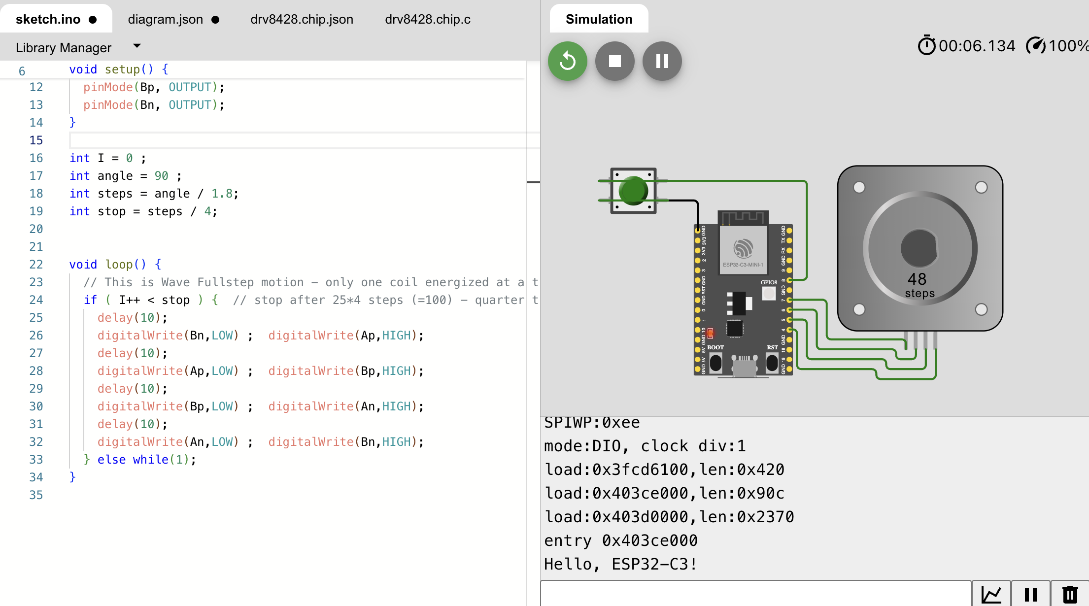
so that I can deal with angles instead of steps. I however was unable to figure out how to do microsteps instead to make it
more precise.
#pictures of the stepper moving 200 and 400
Intro to a Driver
I think I have peaked with this so I am going to move on to using a driver and learning how to control a motor with that.
I am going to use an a4988 stepper motor driver which I am not entirely sure we have access to in HTMAA but I am hoping
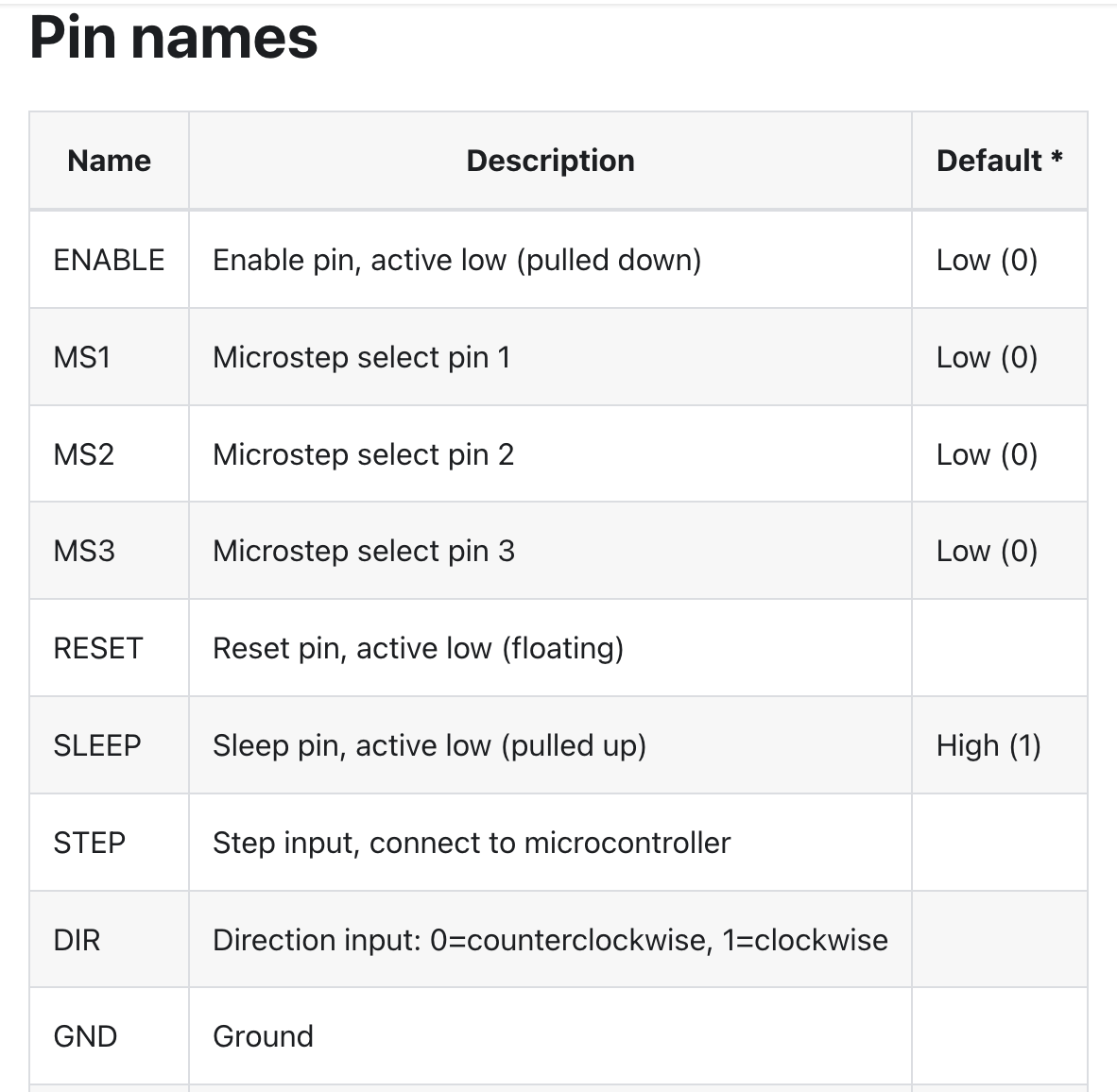
the general principal will apply to the driver that I do have. Okay moving on the pinout of the a4988. Okay it has a lot but
the highlights are the enable, Microsteps, reset, sleep, step, direction, ground, power sluppy, and the ones that connect the
the motors pins, and finally the motor power supply. This driver does alow for microstepping which is exciting and the Microstep
pins I mentioned before are what allows you to pick what type of step you want from regular steps all the way to 1/16 step.
I personally do not need it to be that precise so I'll probably just stick to a half step and see if that is enough.
Wiring a Driver
The way that it works for coding is that you set the DIR pin to 1 or 0 depending on direction
you set your MS pins for the steps that you want and then you pulse the STEP pun to move the motor.
Update I was able to actually find the XIAO esp32c3 so I can program it correctly correctly. I
think I have succesfully wired it so lets code this thing.

Okay so it took me a minute but I was like OMG I have no clue how to actually move it
but then I realized I only have to send HIGH to STEP so lets see if I got this right.
I want a half step so I am connecting MS1 to reset since it is HIGH. Okay so I though I succeeded but
I did not in fact. For some reason my stepper motor managed to move -1 steps. I decided an easier way
to troubleshoot is to attach an LED and see if I can make that work first. That way I can see if it is
my for loop or if it is how my pins are defined. I started off by connecting the LED to pin 10 so it is
both D10 and GPIO10 and now I am messing with the for loop. Even though it does do the for loop it never
actually stops. So if i take it out of the loop will it only do it once? It still isn't stopping I am so confused.
OKAY I GOT IT. Kind of. Apparently since i changed my for loop to an if loop it started working yay. Still doesn't
explain why it didn't work when it wasn't in a loop but oh well. Okay so once I start changing how I works
it stops working. Meaning instead of adding 1 i am adding 0.5 and it broke the whole thing. I FOUND THE ISSUE.
I had defined I as an integer instead of a float so it didn't know what to do with the number 1.5 so
I changed the definition to a float and it works now. Okay so the next step of trouble shooting is with the
GIPO pin definitions. I an going to connect it to D4 which is GPIO6 and see what if needs to be. Okay update it
does need to be 6 for it to work amazing. AHHH The motor is moving!!! Okay there is something slighlty off
because it is changing direction when I haven't changed that but not changing the amount
it should move. Okay so apparently I was doing full_steps when I was calulating for half steps. But
it is finally completed!!!