Documentation
Group Assignment
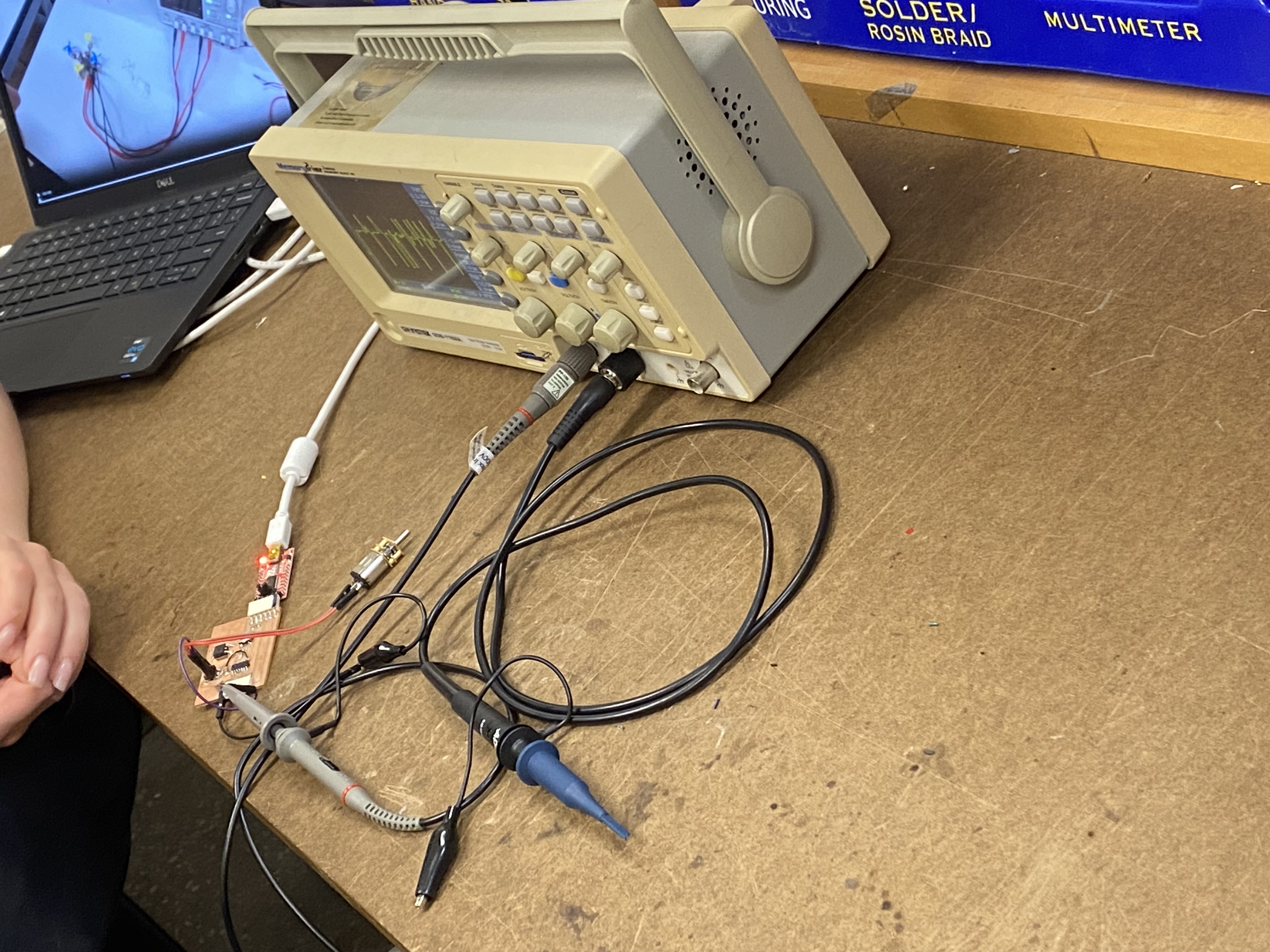
This week's group project we learned how to use a multimeter, oscilliscope, and a variable voltage supplier.
Multimeter: can be used to measure current,voltage, and resistance. It has two probes that you touch against
what you are trying to measure and you move the dial on the multimeter to what you are trying to measure.
The Variable voltage supplier is pretty intuitive its basically like a giant potentiometer where you move a dial
and the voltage being supplied increases or decreases
The schematic
I have previously used Fusion360 for 3D modelling but I did not know that there was a feature to layout electronics and create PCBs. I am hoping to be able to learn how to use both Fusion360 and KiCAD to comapre them and see which I feel more comfortable with.
Fusion360
Starting off with fusion 360 the amount of parts in the library that we have access to is incredibly overwhelming and I cannot tell the difference between some of the components. I decided that rather than just trying to brute force my way through this I am going to look up some online tutorials and try to make a basic circuit. After doing that my plan is to hopefully go to office hours and get some support on how to connect my lcd display and then figure it out from there.
Libraries :(
As I start to dive into I'm realizing that I know even less than I thought. For example, I am currently trying to add a resistor but the first hurdle is what is the difference between R and R-US and then there are different types of pitches for a resistor and also different types. The one I normally use I believe is the first one which is the axial pitch one but there are also chip reisstors and melf which seem to be cylindrical resistors. I will probably end up researching the differences and adding a blurb later. I finished the tutorial! It seems that the actual UIUX is not very intuitive especially when trying to rotate a part or even move it around. I am a bit concerned about how I completely forget everything about electronics apparently but hey might as well refresh in a fun way! My next step will be to learn how to validate it and then turn it into a PCB. hopefully somewhere during that time I will actually find out what this schematic does.
Switching to KiCAD
Taking a break from fusion360 electronics I am trying out KiCAD. From first glance it seems to have a more professional, clean, and easy to use look. The library also seems a lot easier to use and understand
Breadboarding
Going a little bit sideways I decided to start messing around with getting the LCD display to
work. My first task is to get it to work on a breadboard and then pass over that design to a
scehmatic. The main problem of the moment is well... im not sure how to get images on an lcd
display. In my arsenal at the moment I have two batteries, a batter holder, an lcd screen, and
an arduino nano v3. And basically zero wires lol. Time to get to googling stay tuned for the next
paragraph...
I am working with using the ST7735 1.8" color TFT display with arduino.
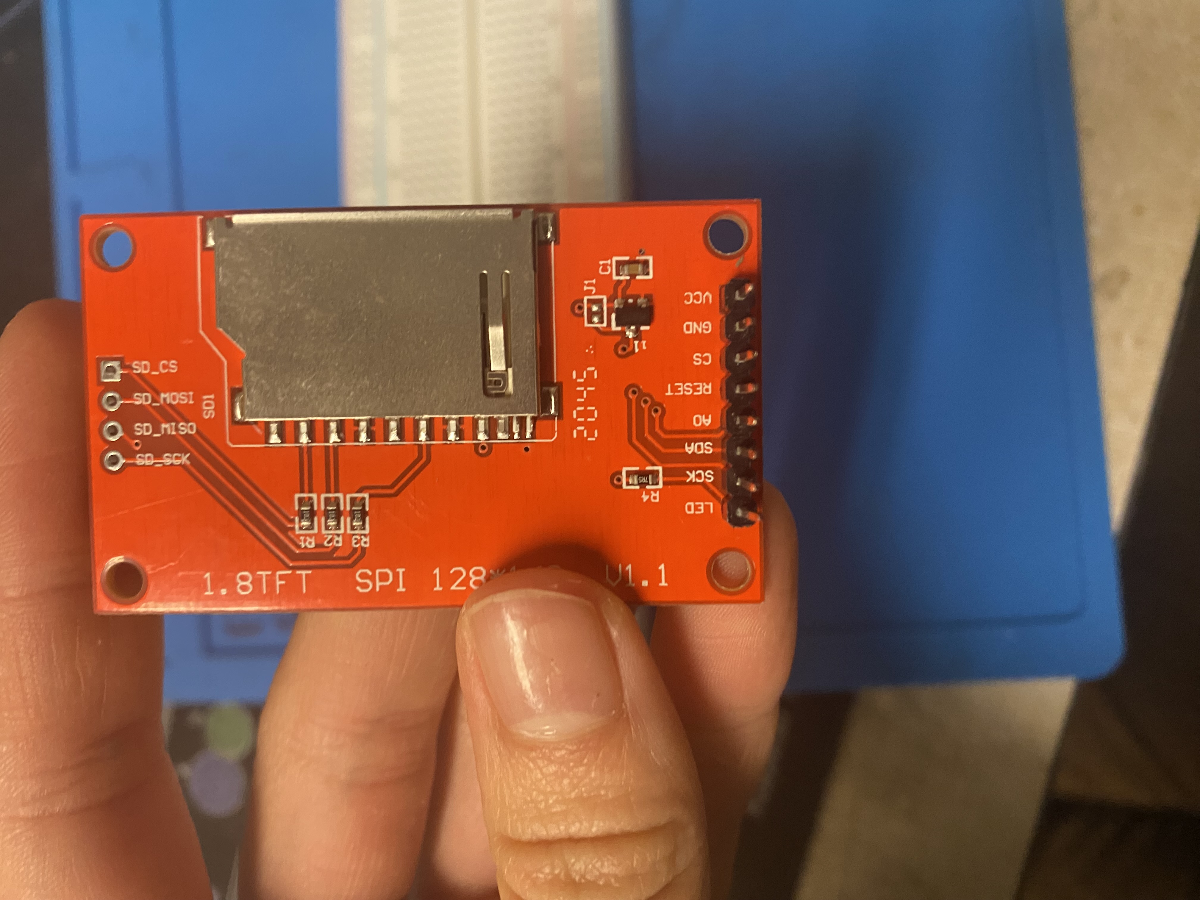
I am starting off using an
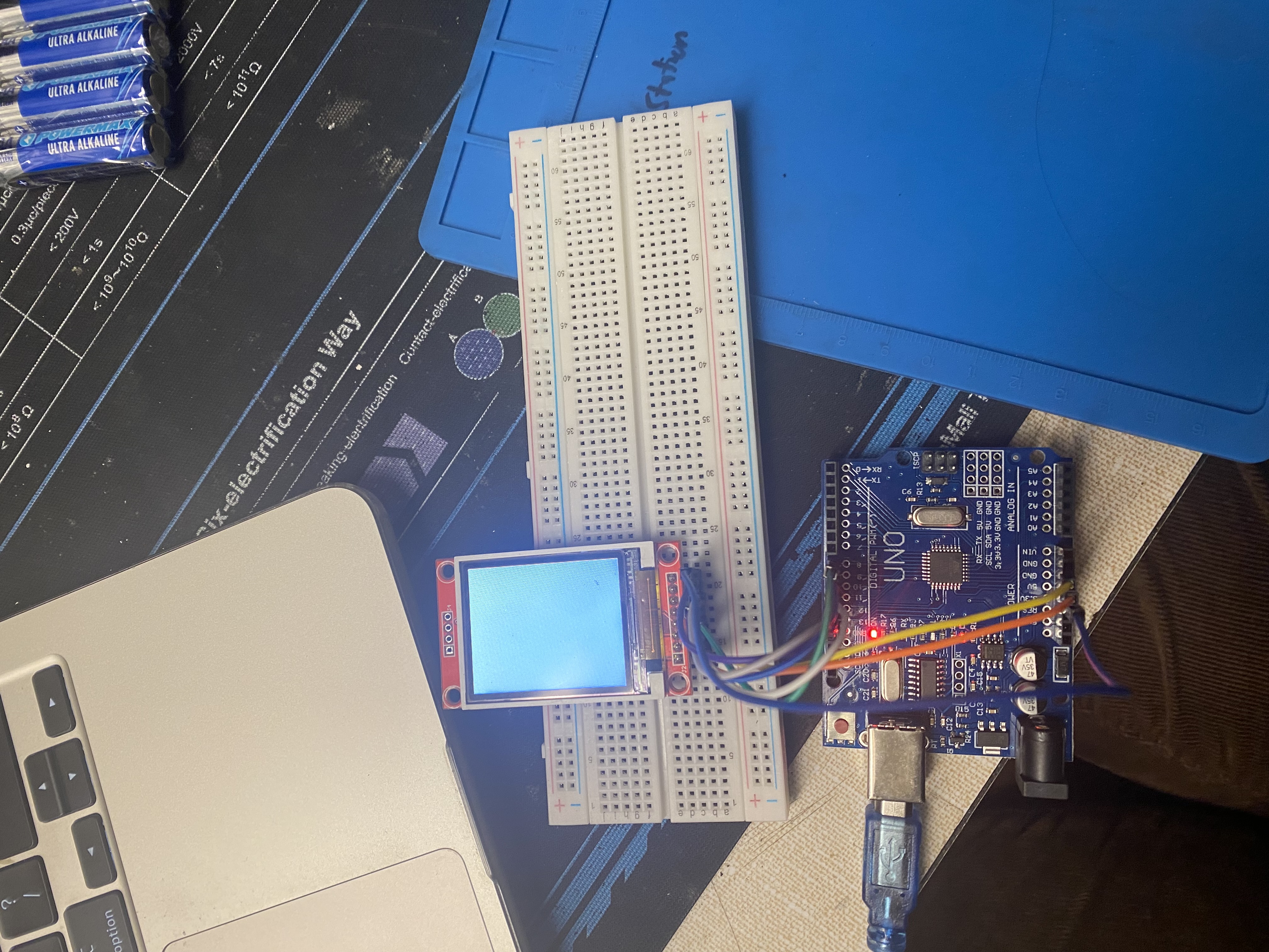
arduino uno because that is the tutorial i found but I plan to switch to a nano once I figure out
what all the different pins connect to. So far I was able to turn on the LCD display and it is a bright
white screen.
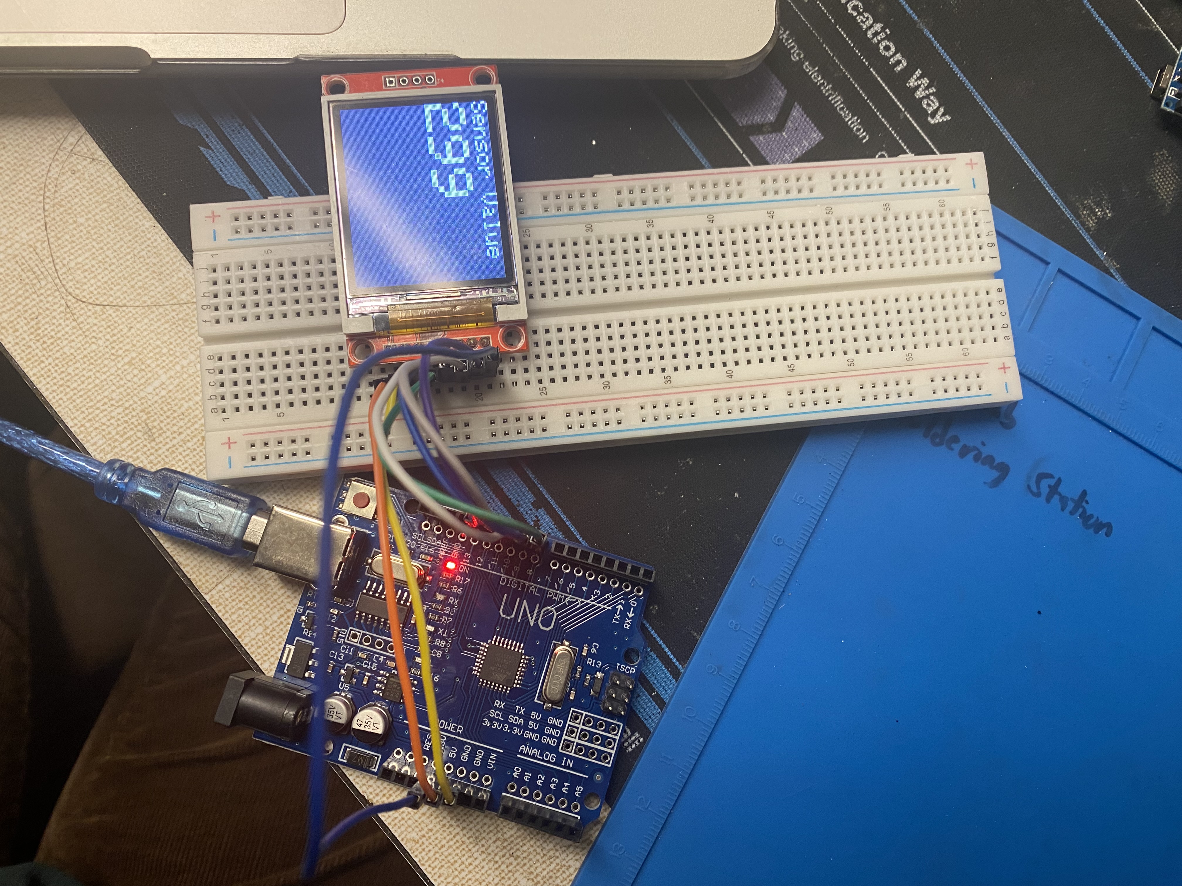
I was able to download some example code off of the arduino examples and get some text
output.
I want to try to switch to the nano next and then work on putting some of my own code on it.
IT WORKED!! the nano turned on the LCD screen. While it loads I realized that although I do have the code
for the actual game I am not entirely sure where the graphics of the game are located so I am beginning
to wonder if I should maybe create my own game using the code that I already have for the actual logic
but just make my own graphics. The problem is that I've never worked with graphics on code before.
It loaded. Unfortunately, I am unable to make it actually display the text like it was doing before it
is giving me a series of error that say there is an uploading error.
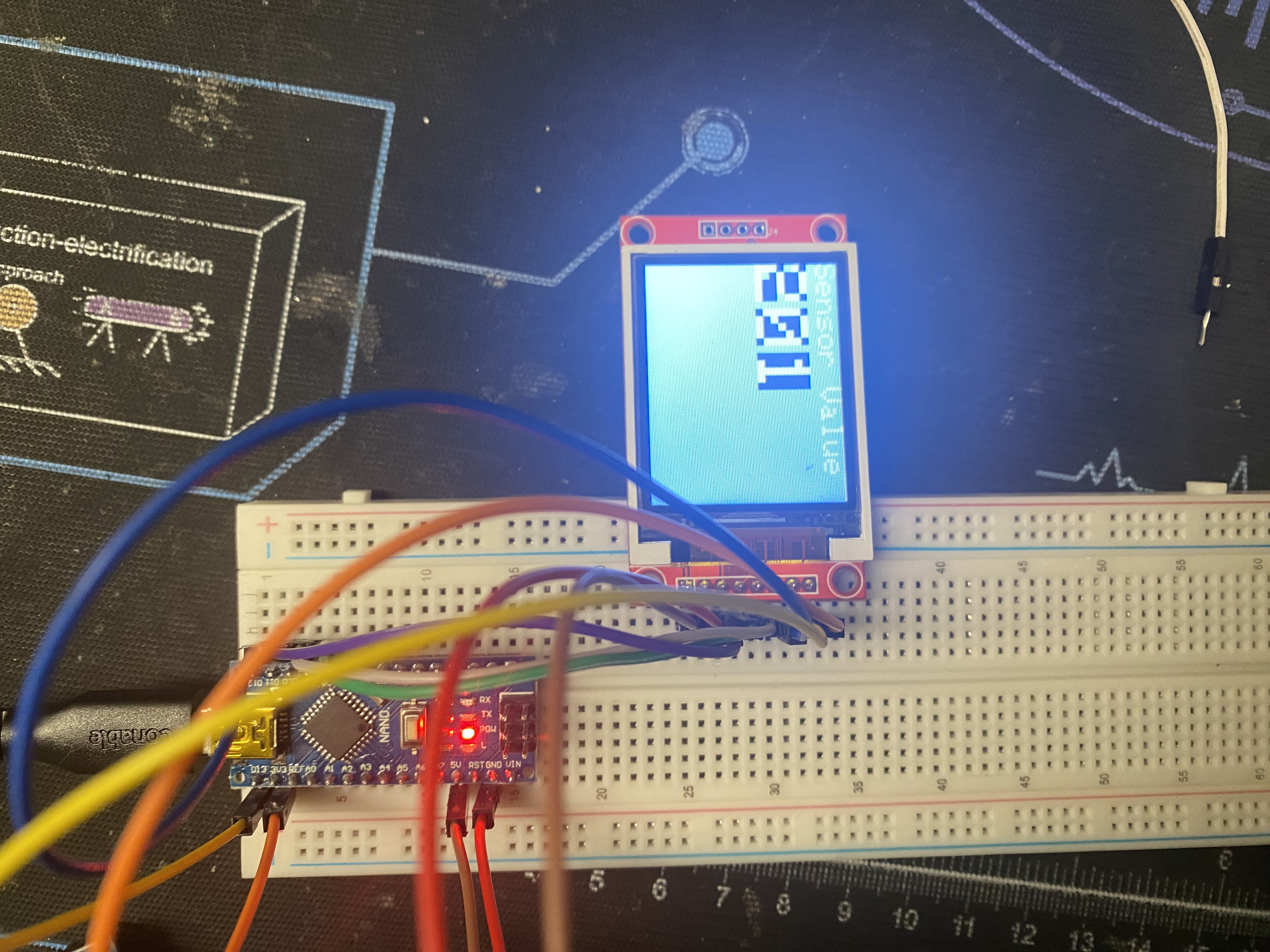
I am not entirely sure what the problem
is. The solution was to go to tools and change the processor to Old Bootloader. I started playing around with
what else I can show on the LCD screen by uploading a program I found that draws rectangles.
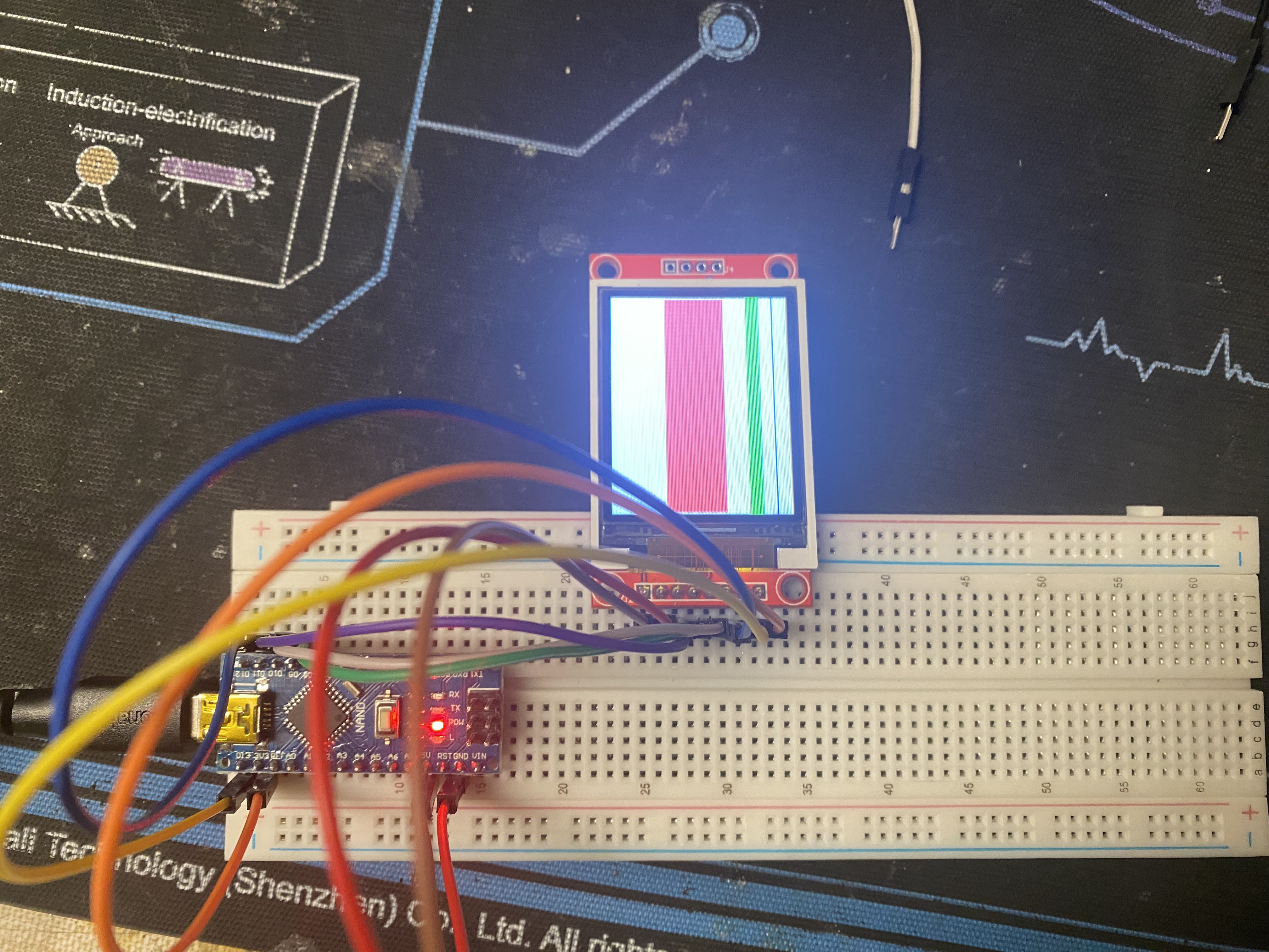
I started messing around with the graphics and was able to draw out the maze for snekoban and the next step
will be attempting to use implement the buttons. I used the example code from arduino for button to write
code that when the button is pressed it draws a blue rectangle and when you let it go it goes back to grey.
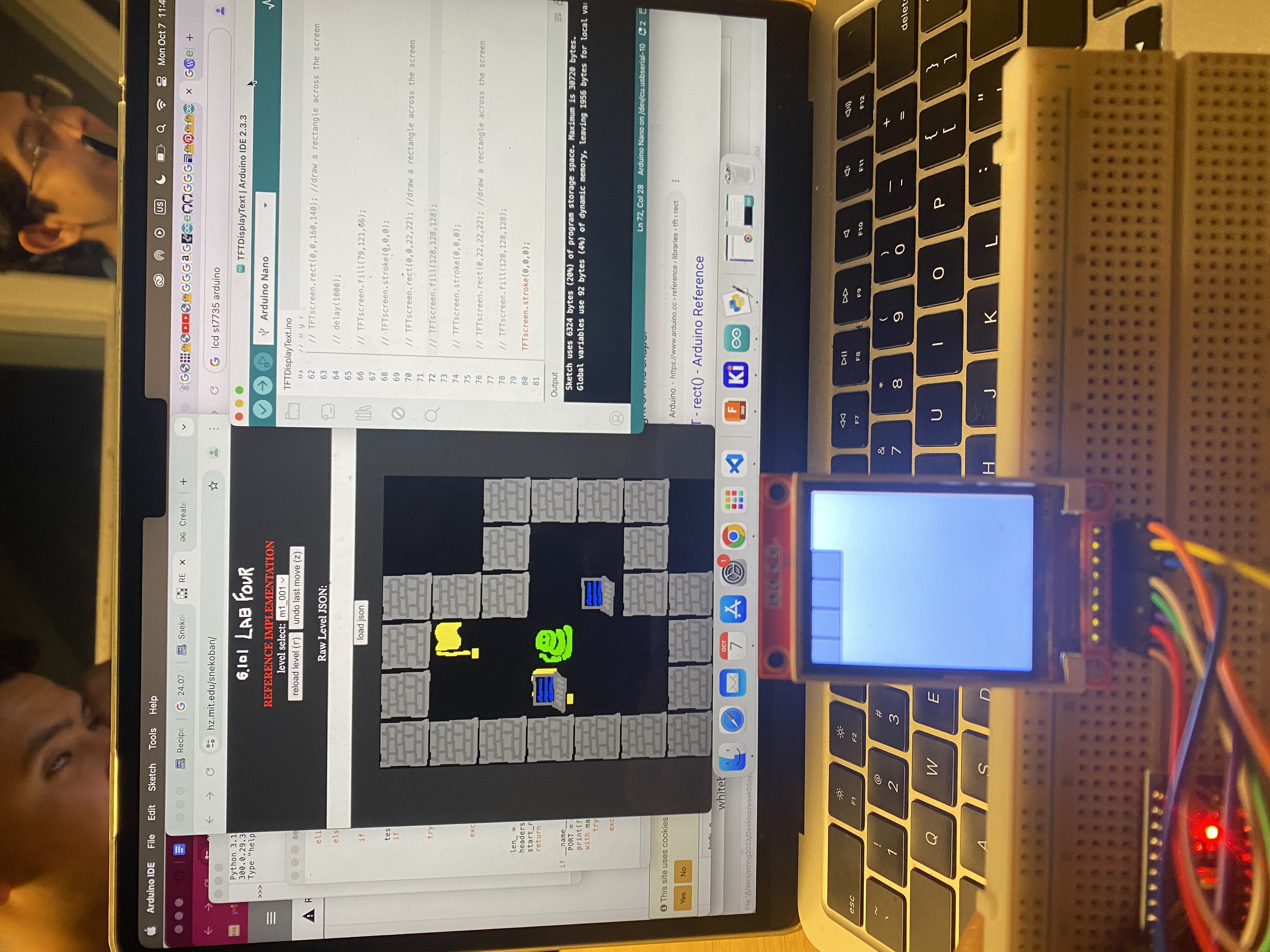
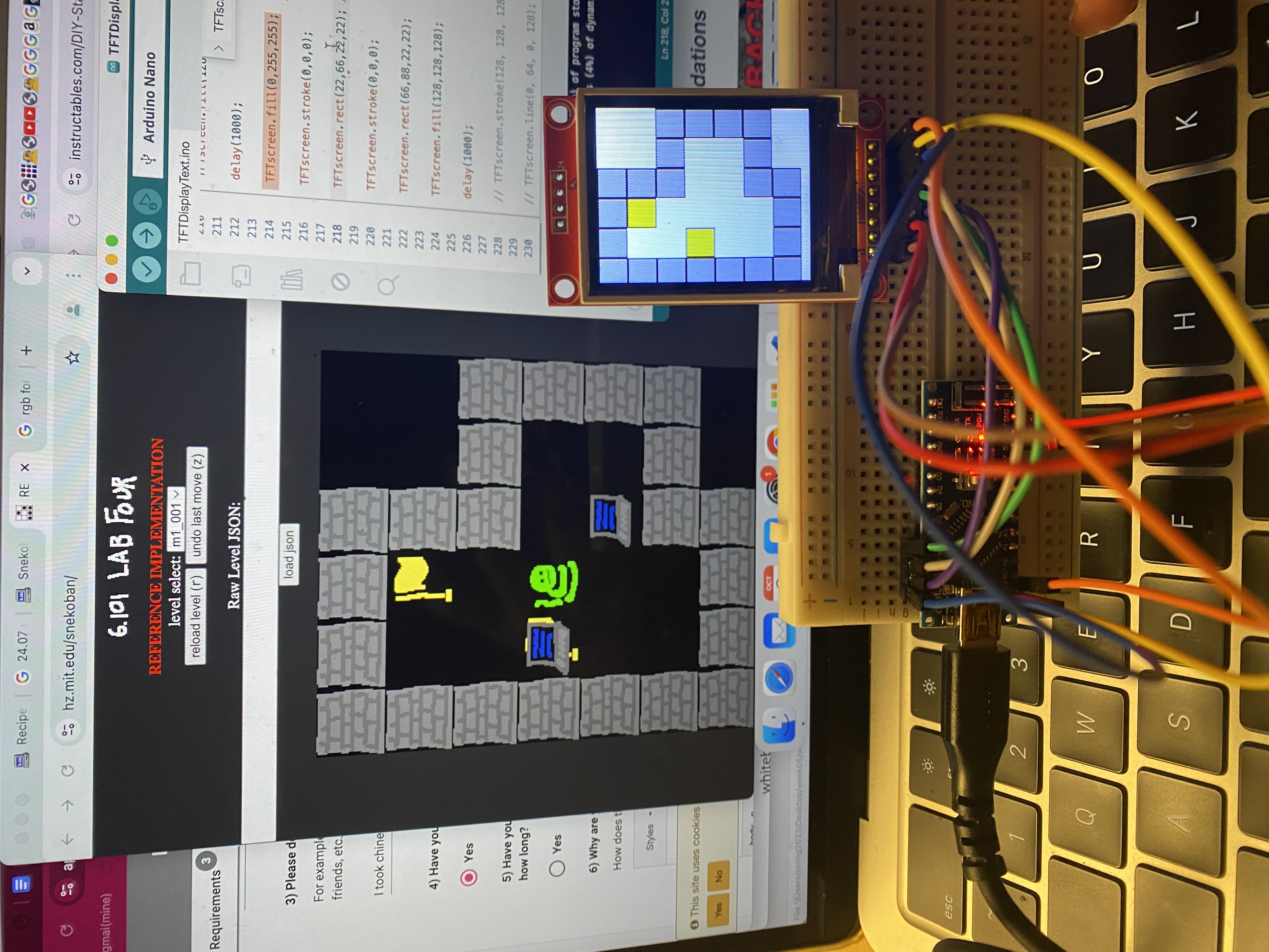
To transfer this over I will have to create a player which is a green square that responds to certain button pushes.
The ideal code for my first button is that when it is pressed the "snake" moves down one block. Right now what
is happening is that although it is doing that it is not deleting the snake position before so it is leaving
a green trail of past snakes. I fixed that issue by updating the square to be white once it passes it which will
lead to be an issue because it will delete the target when it passes over it.
My next steps are:
- finish the breadboard with all four buttons
- draw up the schematic for the pcb and then convert to pcb
- create an array to represent the setup for the game levels
- program the interface with walls ie cannot pass through them
- program so that it will not cover the target if the snake passes over it
- add in the computers
- code so that the computers will function as wanted
- maybe create my own version of an arduino pcb
Coding the Breadboard
I was able to finish the breadboard with all four buttons so I am now currently working on
each button making the snake move in a different direction.
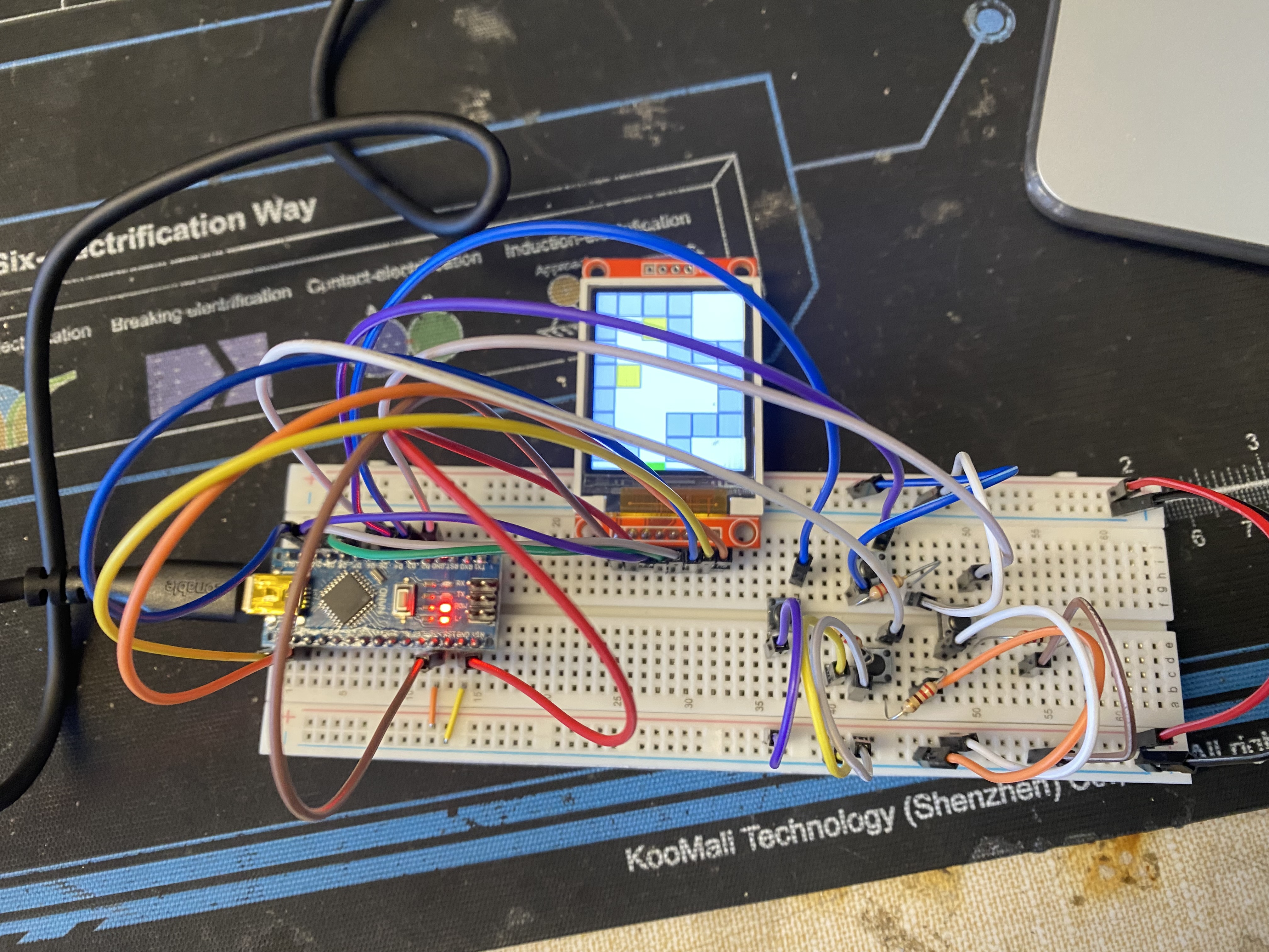
It took a few tries but you apparently
cannot initialize variables in the void loop you need to initialize them outside or else you may
get an error at least for the digitalread. To simply things I simply made it print the direction
it is supposed to move the snake in but now I will add in the actual code to make it move the correct direction.
Now that that works I am going to try to convert the breadboard into a pcb. Wish me luck! As I am
finishing up the schematic for the PCB I am a little concerned because the arduino nano v3 schematic that I found
does not look to be the same as the one I am currently using. Apart from that I want to switch buttons
to a 3 pin button that gives me more height so that it can come out of the gameboard but the ones that
I am currently putting in the PCB have four pins. When I found the schematic I didn't realize they
had only two outputs so I have to read the data sheet to find out where to connect the digital wire
that can actually read the button's signal. After I finished my schematic I attempted to switch it over
to a 3d pcb design on Kikad but I ran into some trouble with the libraries and it saying that it did
not have access to the components I added on the schematic.

Creating the schematic
i was able to fix the libraries issue and import in all the parts. I think Kicad has a more refined
cool look to it so im taking preference to that. It is also a lot more intuitive to get the layers
and the different paths. I am a little bit worried that I did not end up doing it right. It was a bit
confusing toggling between the back and front layer I think you need to hide the front to make the paths
in the back. In the end though it looks really nice and it felt like solving a puzzle! I am a little bit
confused about the paths. The 8 pins that represent the LCD seem to be all connected together which
I guess makes sense but also how am I supposed to know everything is being connected to the right pin.
Apart from that KiCAD has a 3d viewer!! It is so cool to be able to see what the actual PCB would look like.
I forgot that I needed to make an edge cut which basically determines the edges of the PCB. I think I have
to cut off one end to make sure the usb port can connect but I'm not really sure. Apart from that
I'm using small buttons that I wanted to change to make it taller for the gamebox but it seems it might
not happen and I'm worried the look won't be as clean and refined as I wanted it to be.
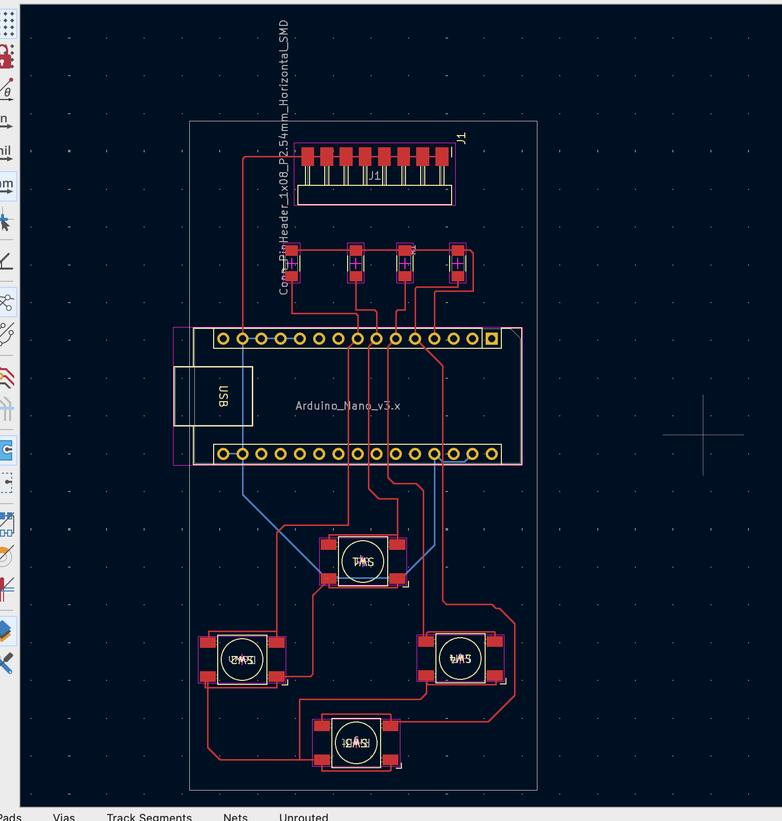
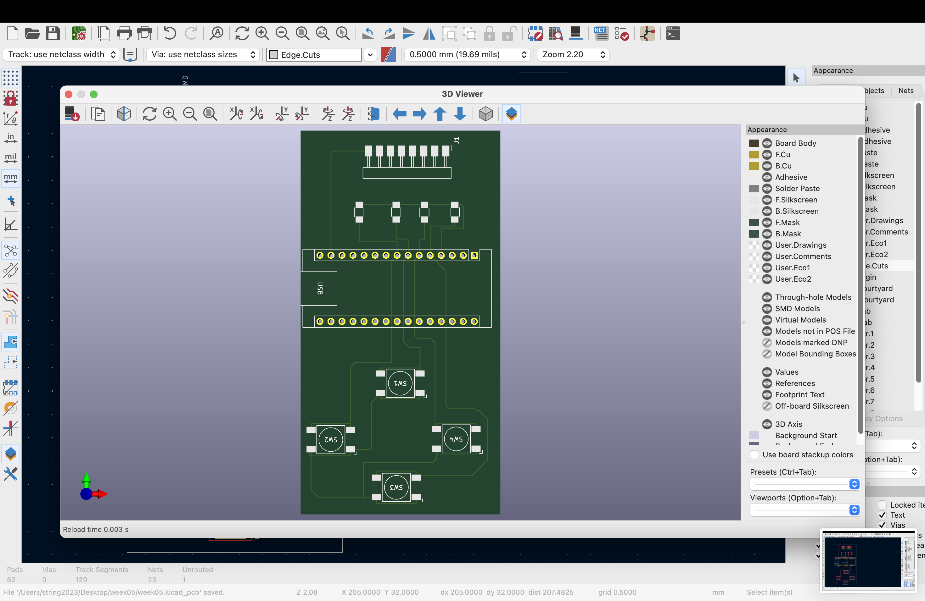
BUT I JUST DESIGNED MY FIRST PCB THIS IS SOOOO COOL.