Documentation
PCB Design
Last week I had already made the PCB and put it into the 3D modelling. However when I went to office hours
I learned that there were a few steps I had to make sure happened. I had to make sure that the minimum trace
and minimum trace width was 0.4mm. I then had to run a DRC to see if I had any issues. Apart from it having multiple
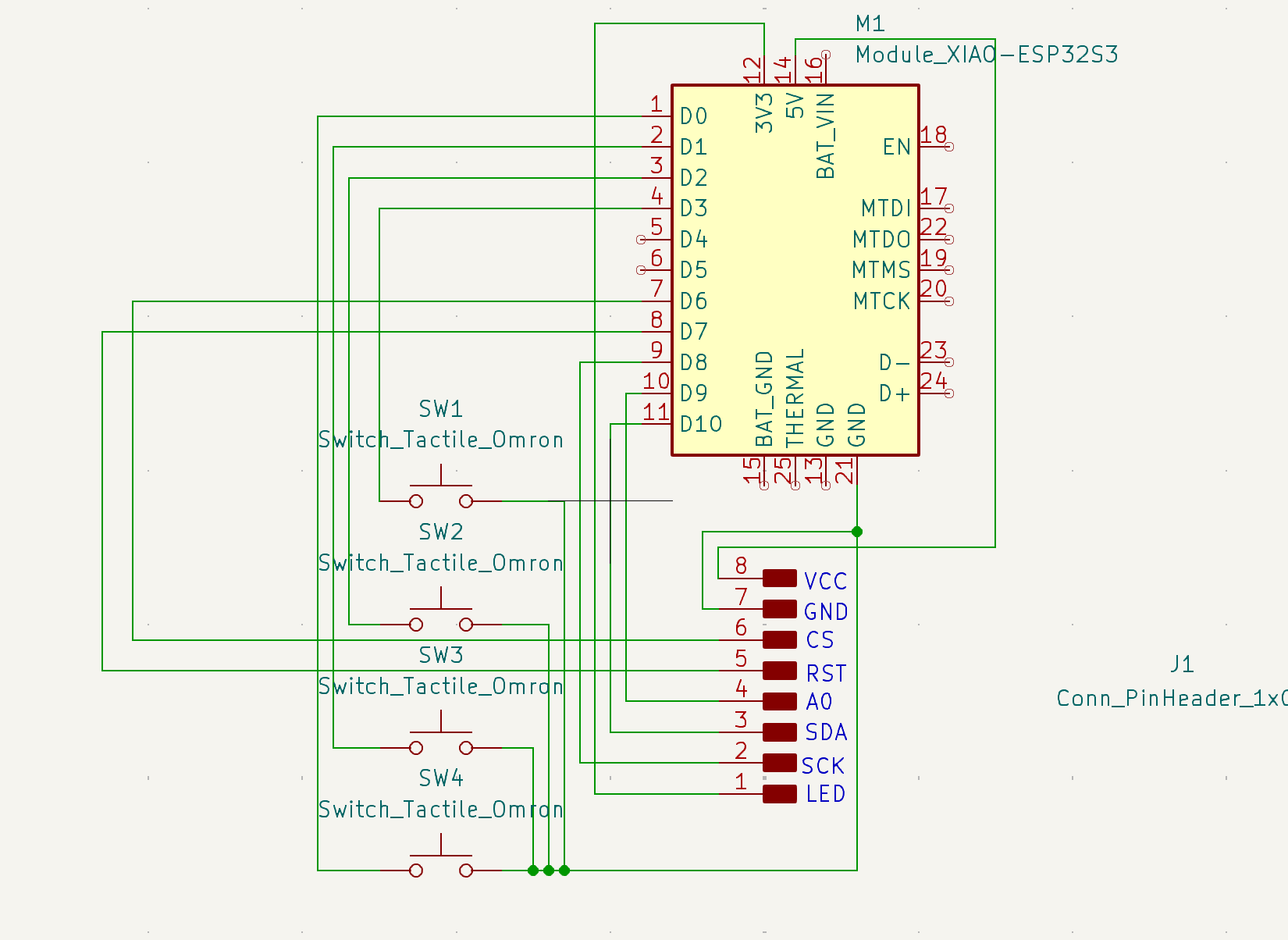
issues I had to redo it all over again so that it was not with nano but instead with a seeed xiao esp32s3.

EECS Try 1
This is going a little bit into the past but before I switched everything over to a seeed xiao i went to the EECS
lab to mill it with the Othermill but then I ran into an error where it said I didn't have anything on my gerber files.


The Cutting
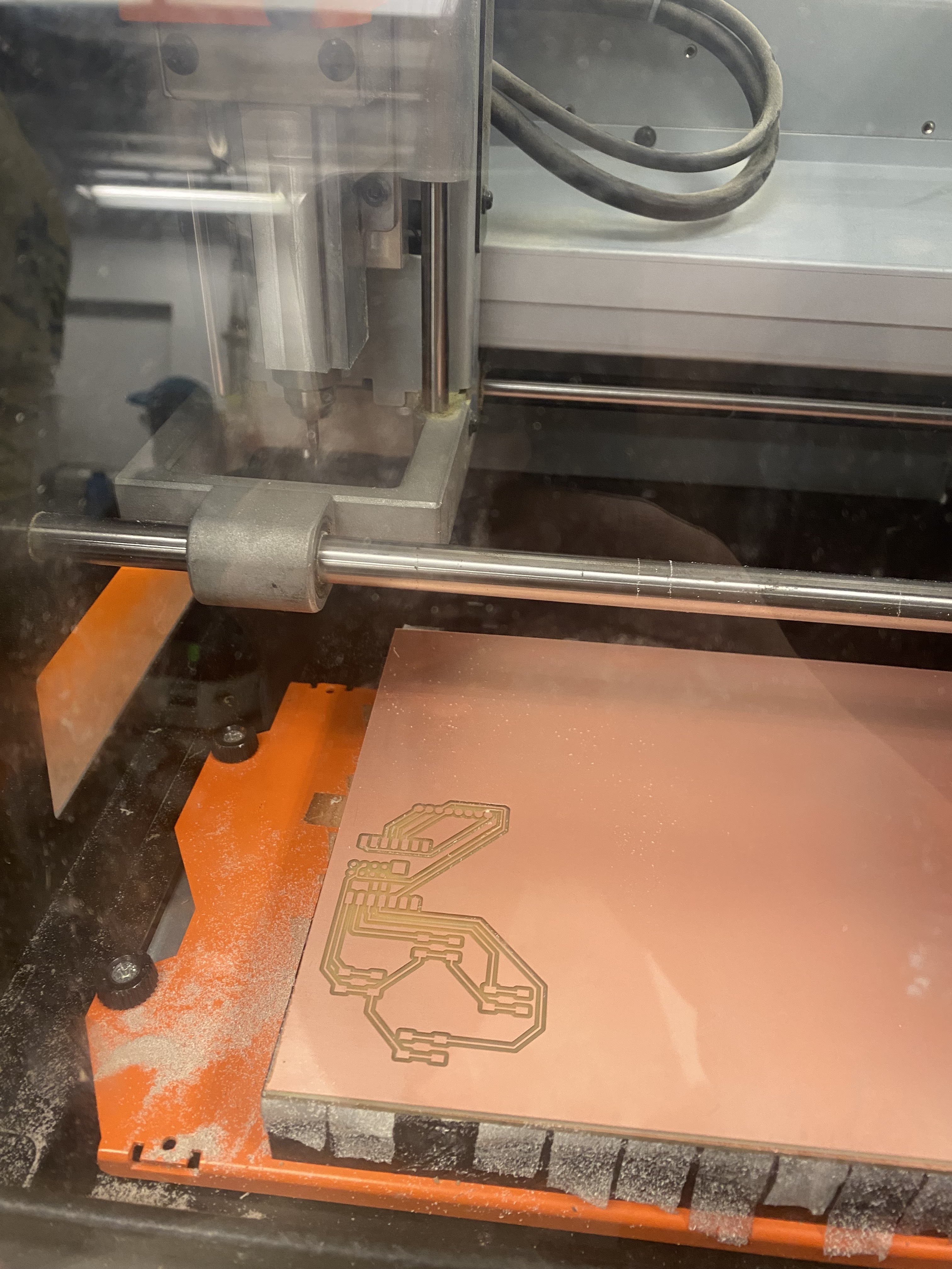
I am currently in the archsops trying to cut a PCB for the first time by myself. I have the
mods open,downloaded the gerbers,switched them over to pngs and I am ready to cut.


I already zeroed
the origin and to zero the z you unscrew and drop the endmill by hand. Unfortunately my first try the PCB didn't
fit into the copper board that I had. In the second try for some reason the traces were being cut wayyy too much
and they almost all broke and then the board itself got untaped from the overlay so I had to stop the entire process.


This is now my third try and I am hoping that it will go well this time. I made sure that all my traces are a minimum of 0.4mm
and the distance is also a minimum of 0.4mm. I also moved the copper over to the other less used of the overlay
and made sure to use a lot more strips of tape. andddd it didn't work. The bit is cutting in some places
but not necessarily all the places.

I think it might have something to do with the overlay not being flat
or maybe i got bubbles and my piece just isn't flat? I think I am going to go EECS tomorrow and try to make it there.
To try to fox it I stopped it and didn't move the origin but made the z a little bit deeper and maybe hopefully that
will work and resent the file and I am currently cutting it right now. It WORKED. Now for some reason it decided to start drilling
the holes in the wrong location?? It seems that when I rendered the cuts it was on the wrong size board.
Thank God that the holes did not cut through the traces. I was able to fix it and now I have the PCB! I have to go solder it tomorrow.


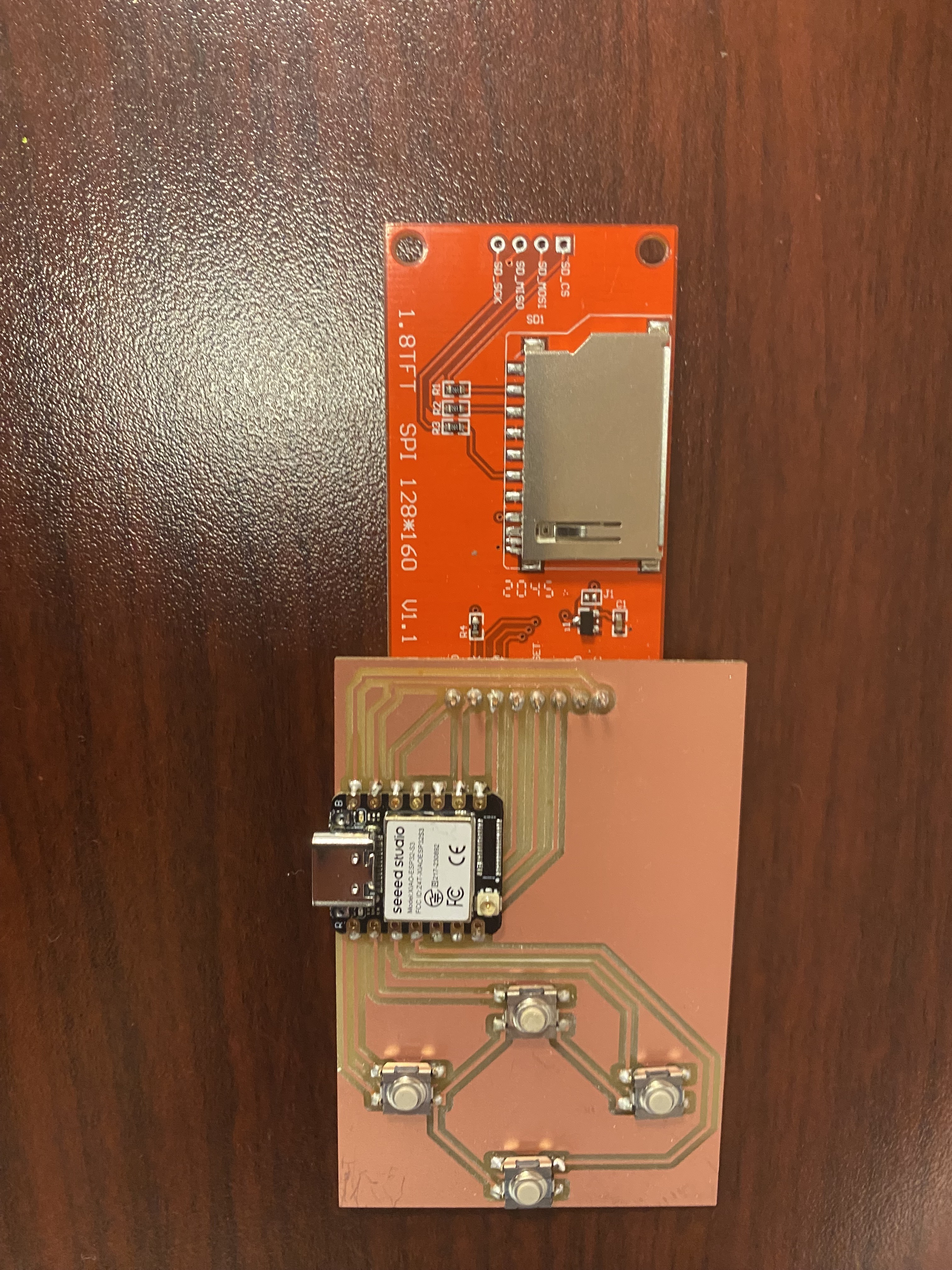
Soldering
So I went in to the EECS lab today because I could not find solder paste in the architecture shop. I started to
use the heat gun but I think I ended up slightly burning the solder. It is apparently supposed to be ~300F. Apart from
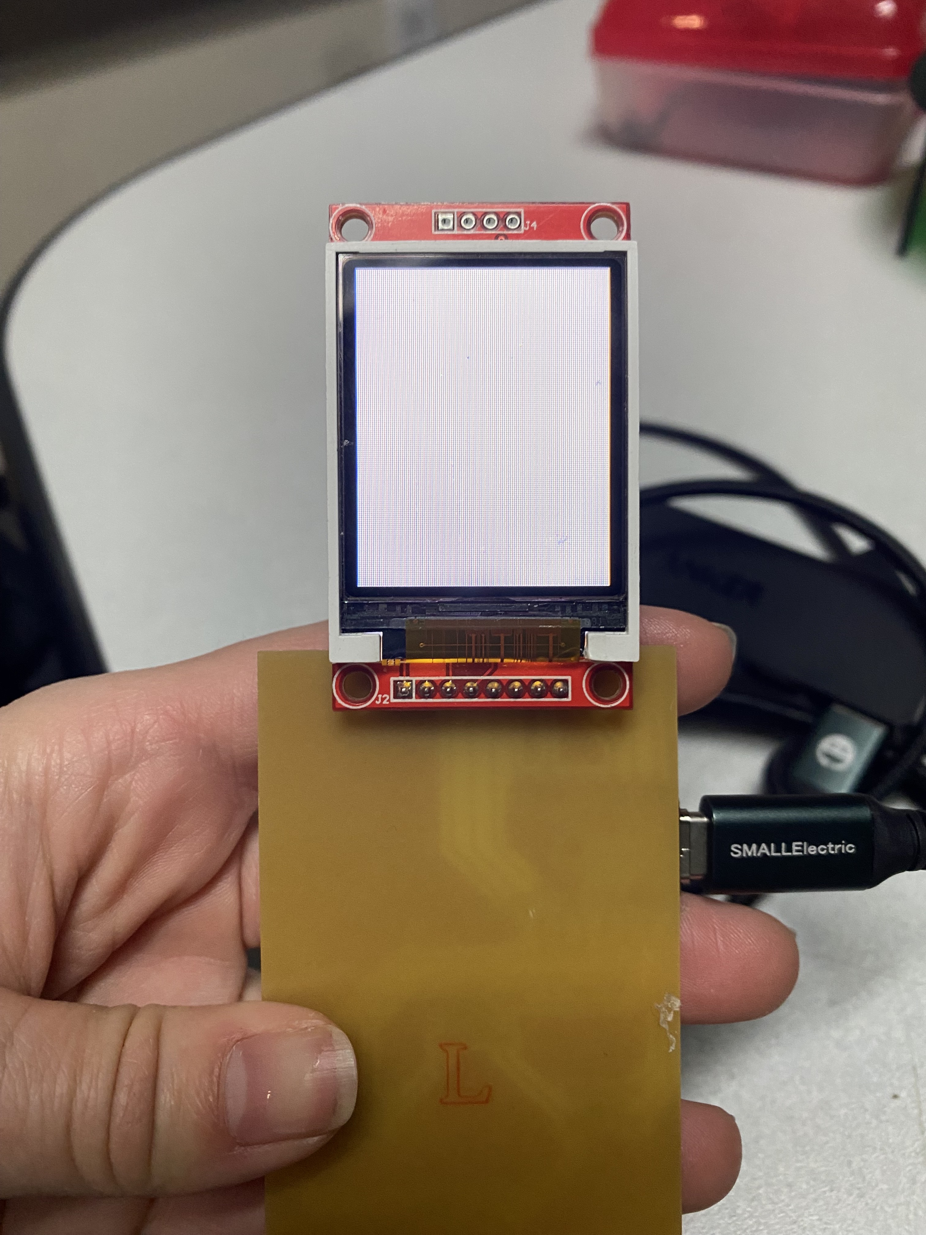
that I ran into an issue with my LCD screen. Since the LCD is through-hole I was not able to solder it in normally and i had
to offset it a bit to be able to solder it to the PCB but then I tried to turn it on but apparently I forgot to draw a trace
to the LED meaning I gave it no power so now it won't turn on.


Updated PCB
So I decided that while I was at it I might as well check to make sure all the LCD connections are working so I
updated my breadboard and verything worked as long as the LCD LED pin was powered by 5V so I was so ready to
put it into the schematic but then one of my traces is stuck no matter how much I try I can't get it to
it's right pin. OH MY GOD. It took me at least half an hour of staring at the PCB but I was finally able to
figure out a way for all the pins to connect and I can finally mill it again!!

It was actually able to turn on this time but when I tried to push the code from arduino I ran into an error
with the libraries and it wasn't able to push the code and I have honestly no idea how to fix that issue.
SOOOOO apparently some of my wiring is wrong and I have to remake the PCB again. Apart from that we downloaded
a different TFT library with Adafruit and I have to switch over all my code and hope that it works apart from redesigning
the PCB.
After redoing the PCB I noticed that I had still done something wrong I flipped the entire header so where 1 is supposed to
be 8 is there instead so I kind of gave up and soldered it upside down. It should hopefully work now and I will
just remake the PCB after my finals. I tried to push code but for some reason the sketch doesn't even compile and the
esp32s3 is blinking orange?? The push will continue after finals to hopefully make it work work.