Documentation
Chose Your Sensor
I am going to break this project down into quite a few steps to make it feasible as I am going out of town for the entire weekend.
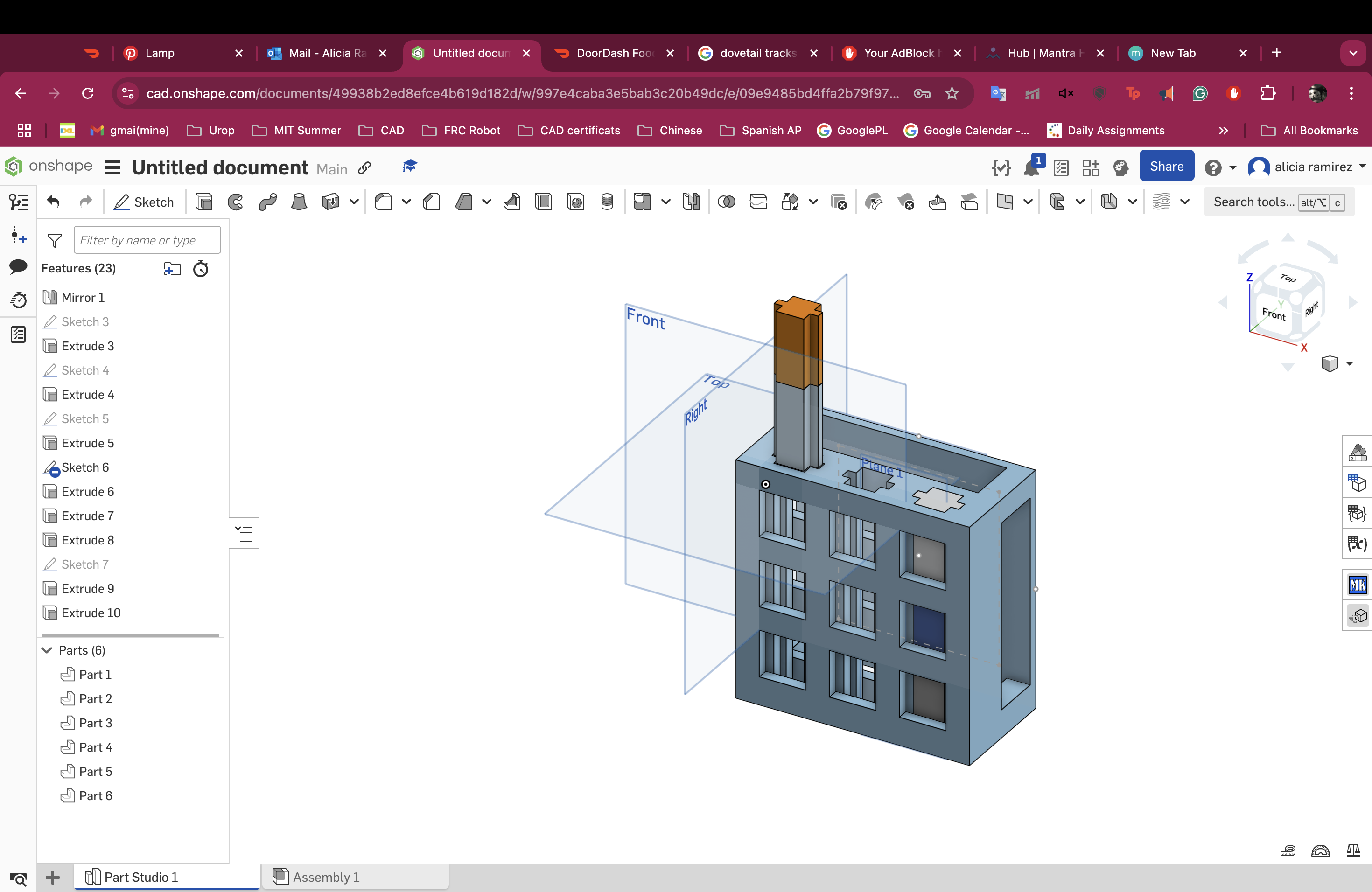
Designing the grid
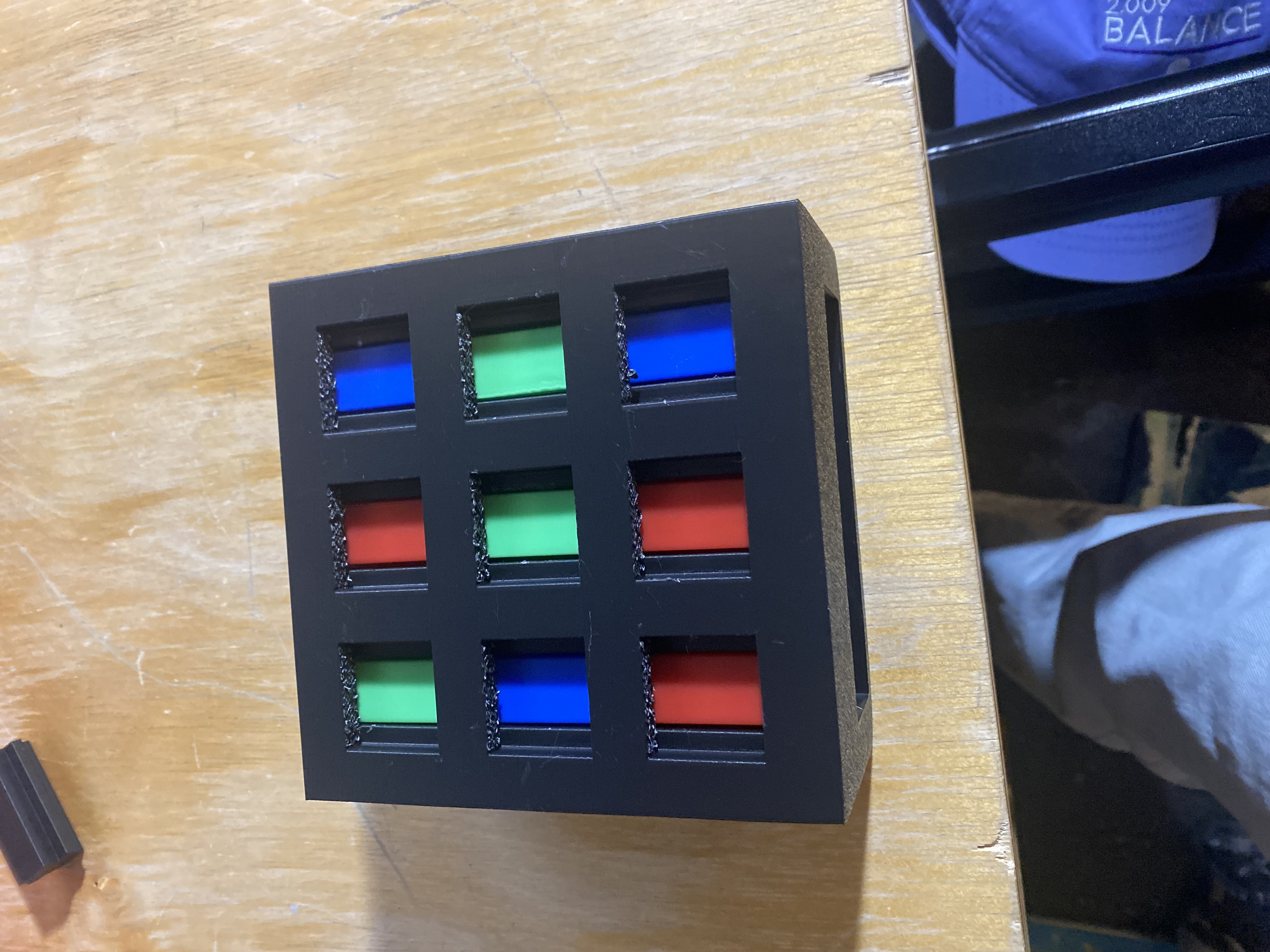
I started designing the grid wanting it to be 3x3 with blocks of different colors inside.
I want the blocks to slide in cleanly so I am hoping to use dovetail tracks and then have nine color
sensors on the bottom that are each in charge of one block.
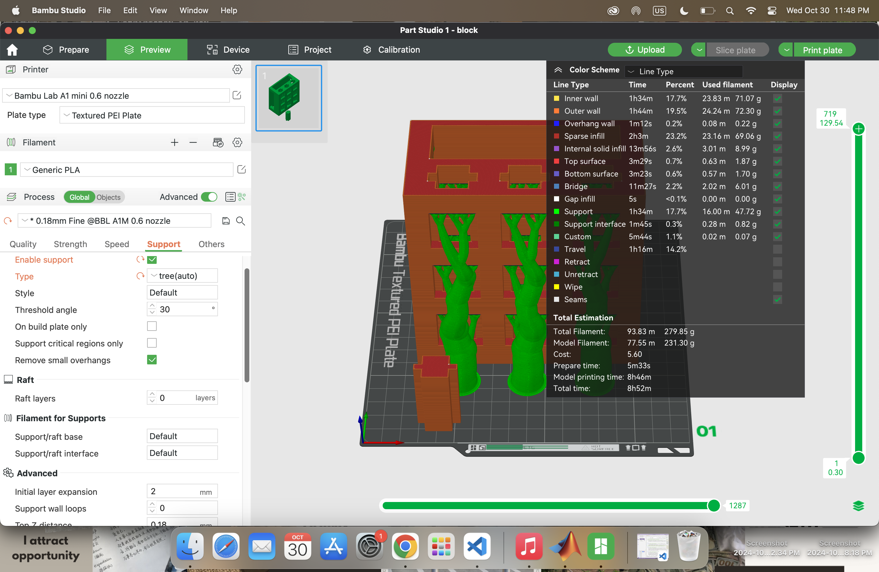
I was able to print it almost without flaw
the only problem was that I ran out of filament and did not notice the print had not finished when I grabbed it.
In conclusion I had to reprint it. It is pretty clean but I could've made it a lot smaller and a lot less clunky.
Hour 0 - CADing the mechanical arm
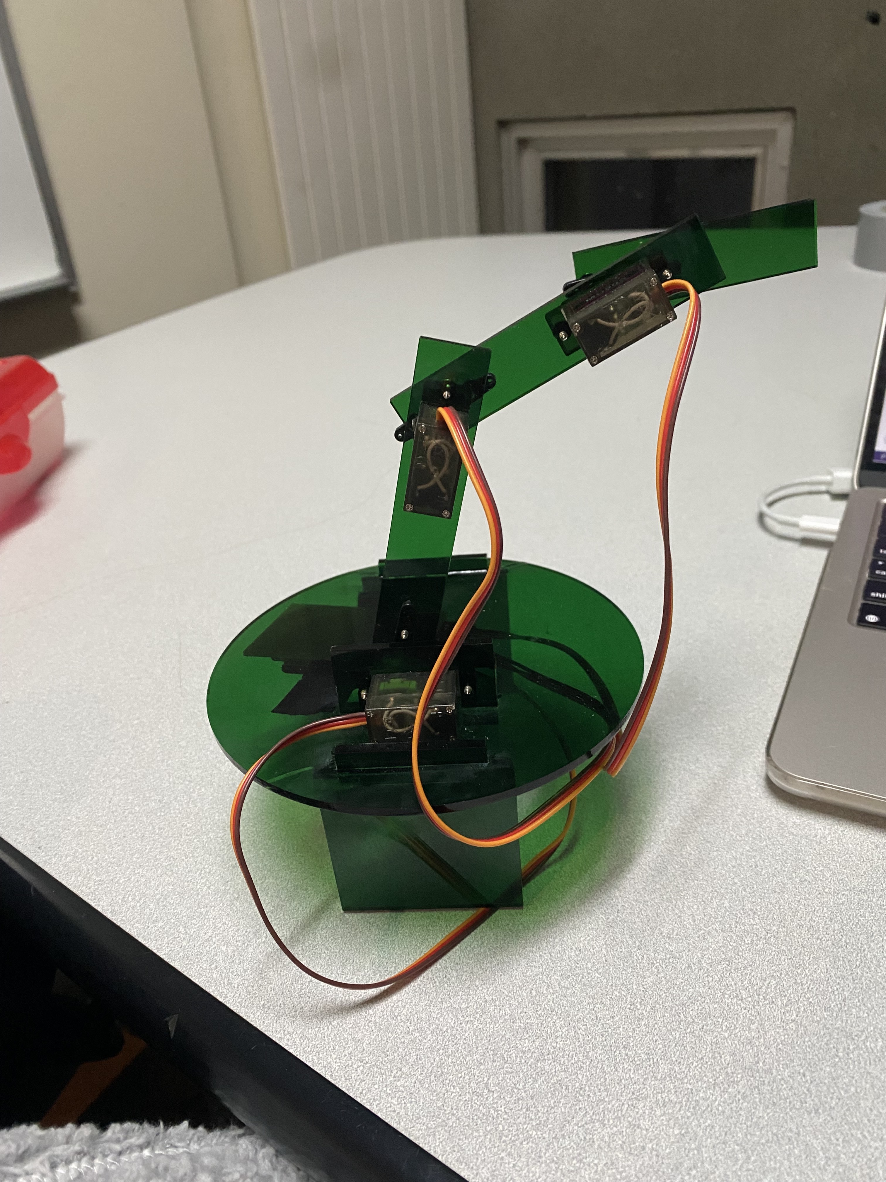
I started off with a rough sketch knowing I wanted to put in three motors.
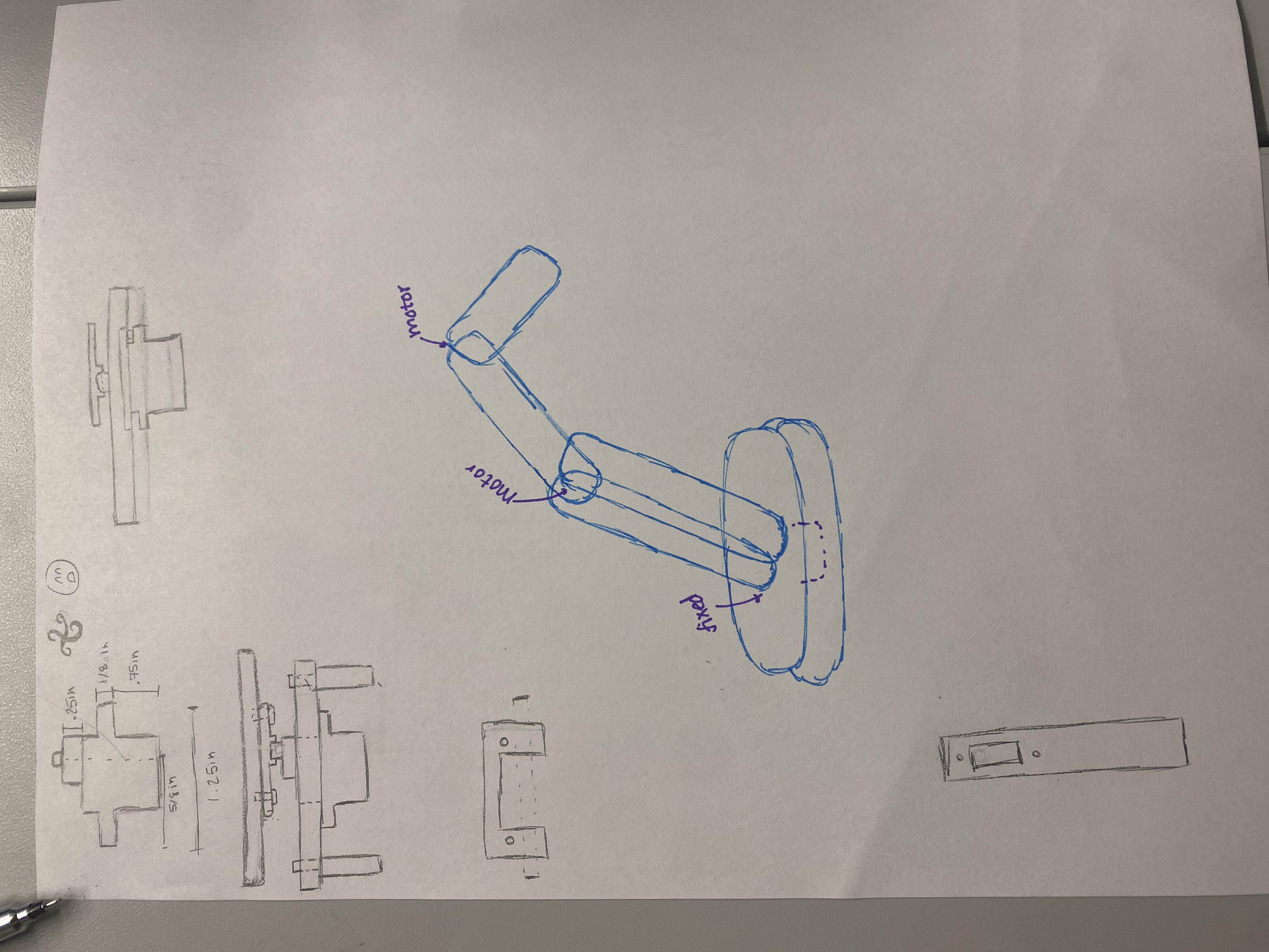
I initally wanted to make it
rotate as well but that ended up being too much with my time constraints. I was able to download a 3D
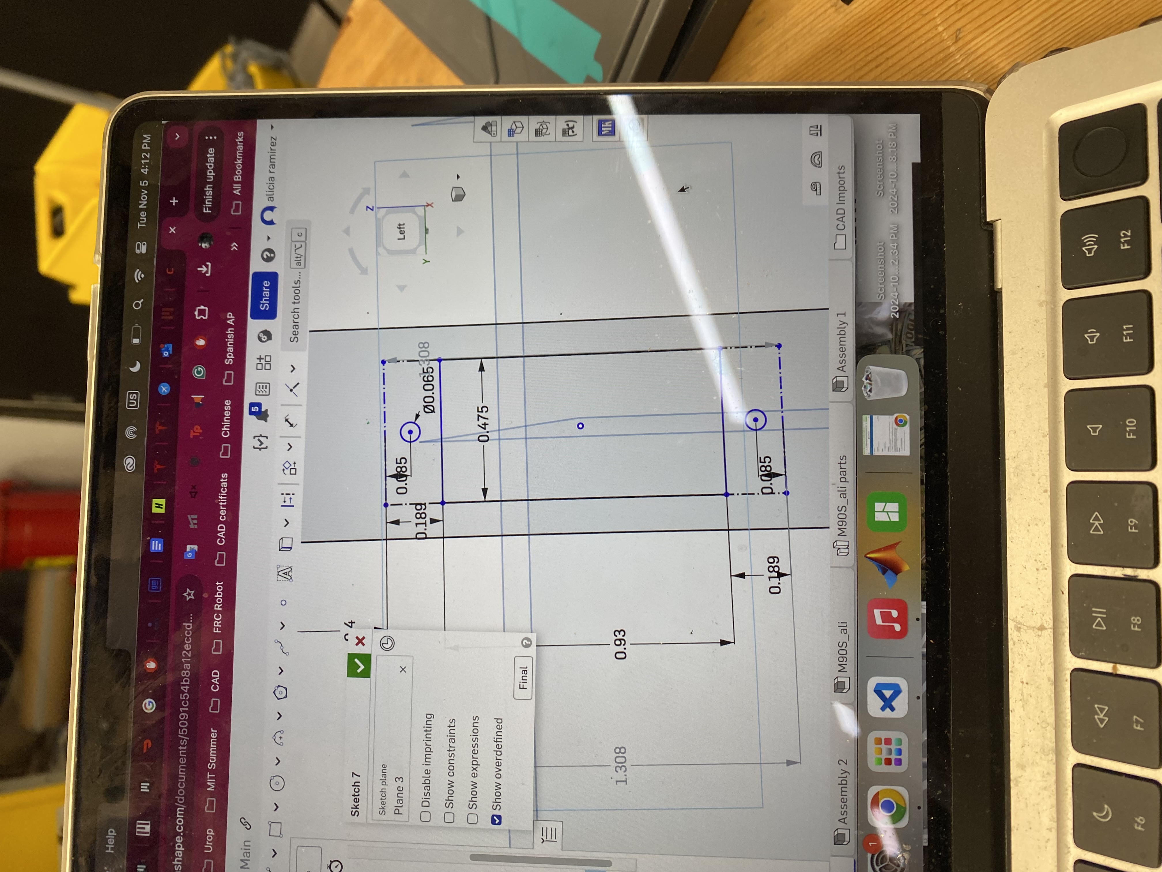
file of the motor which made the CAD a lot easier but I am not sure it is going to come out exactly the
size that I want it to be. I guess we are going to cut it out and see what happens.
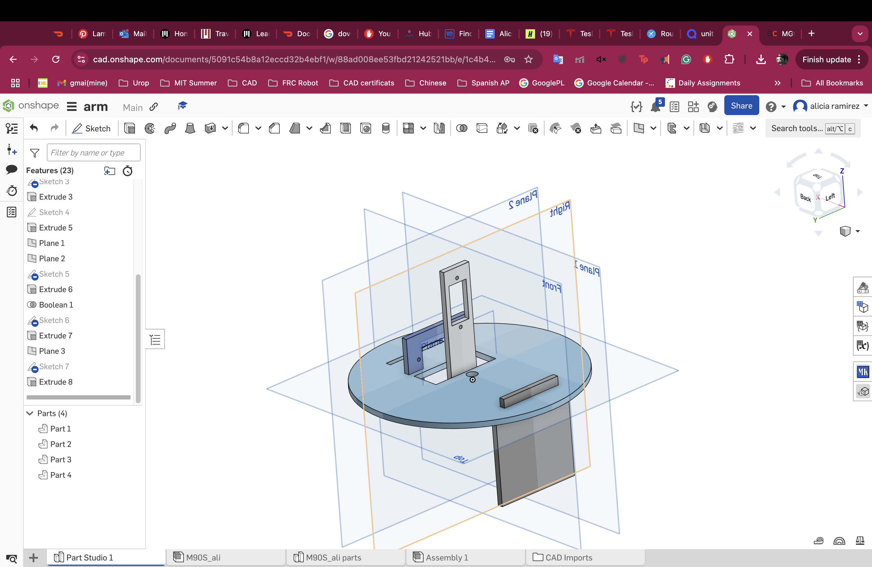
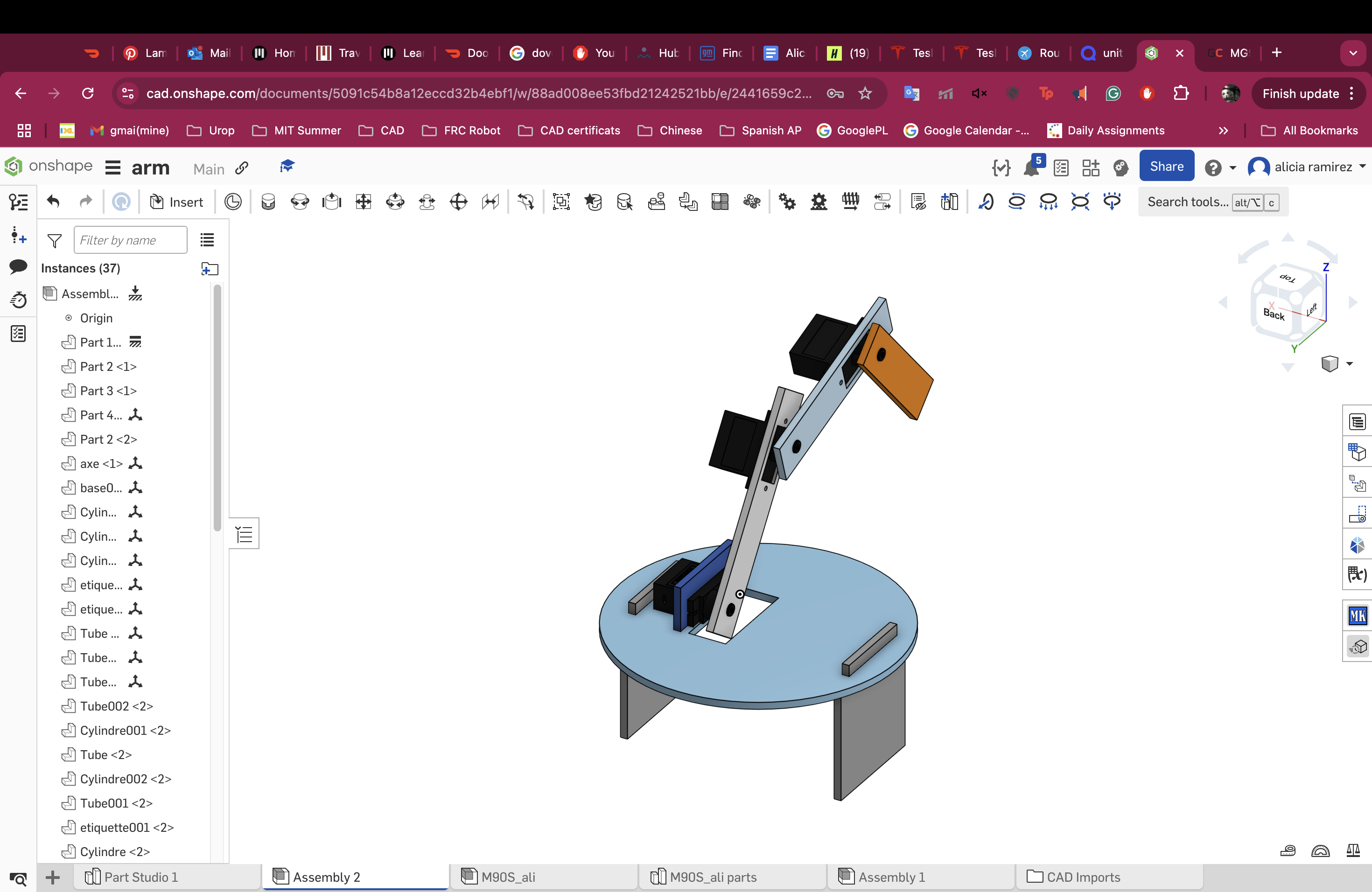
I don't really love
how the servos come with little things that can attach to the top because they seem kind of weak and i am
not sure it will be able to hold with just the screws under the torque I am going to put it in.
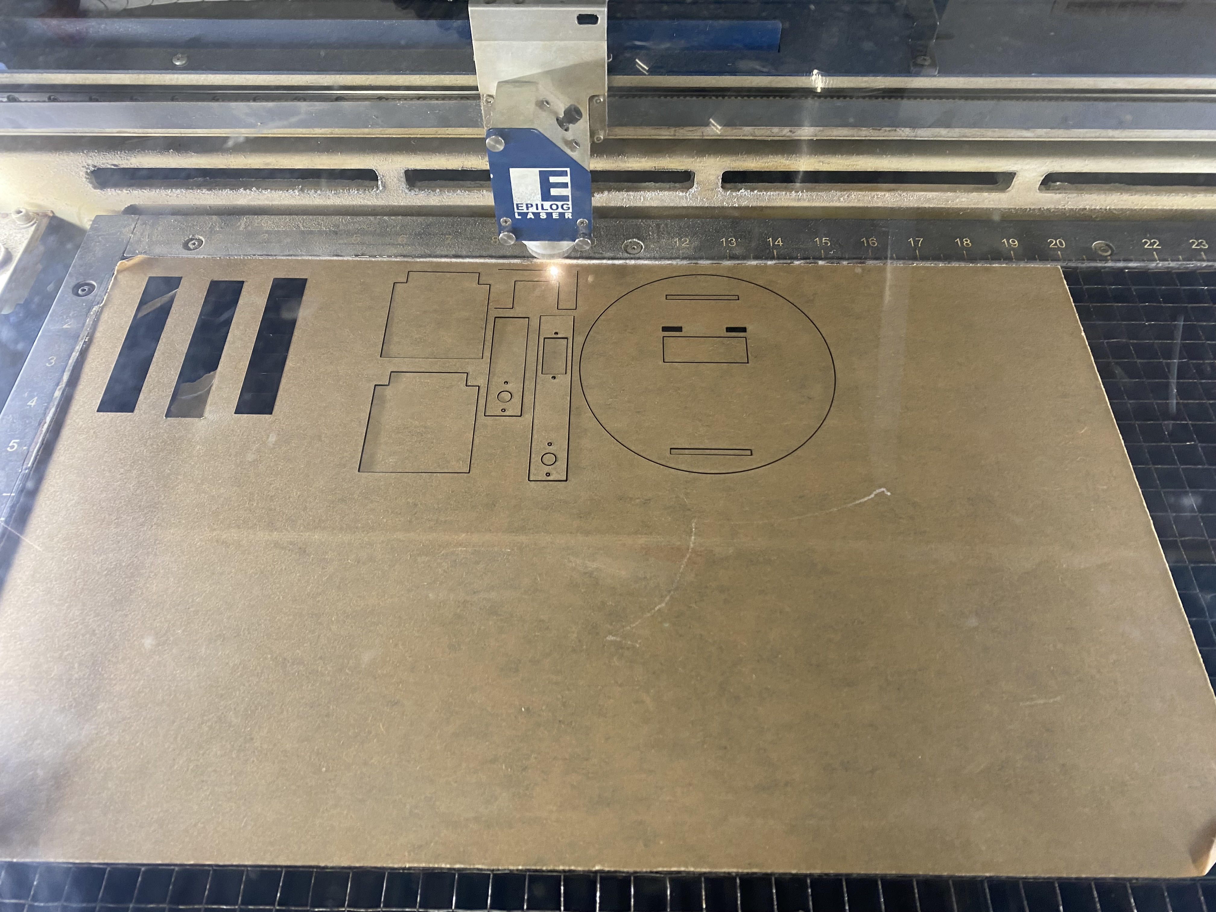
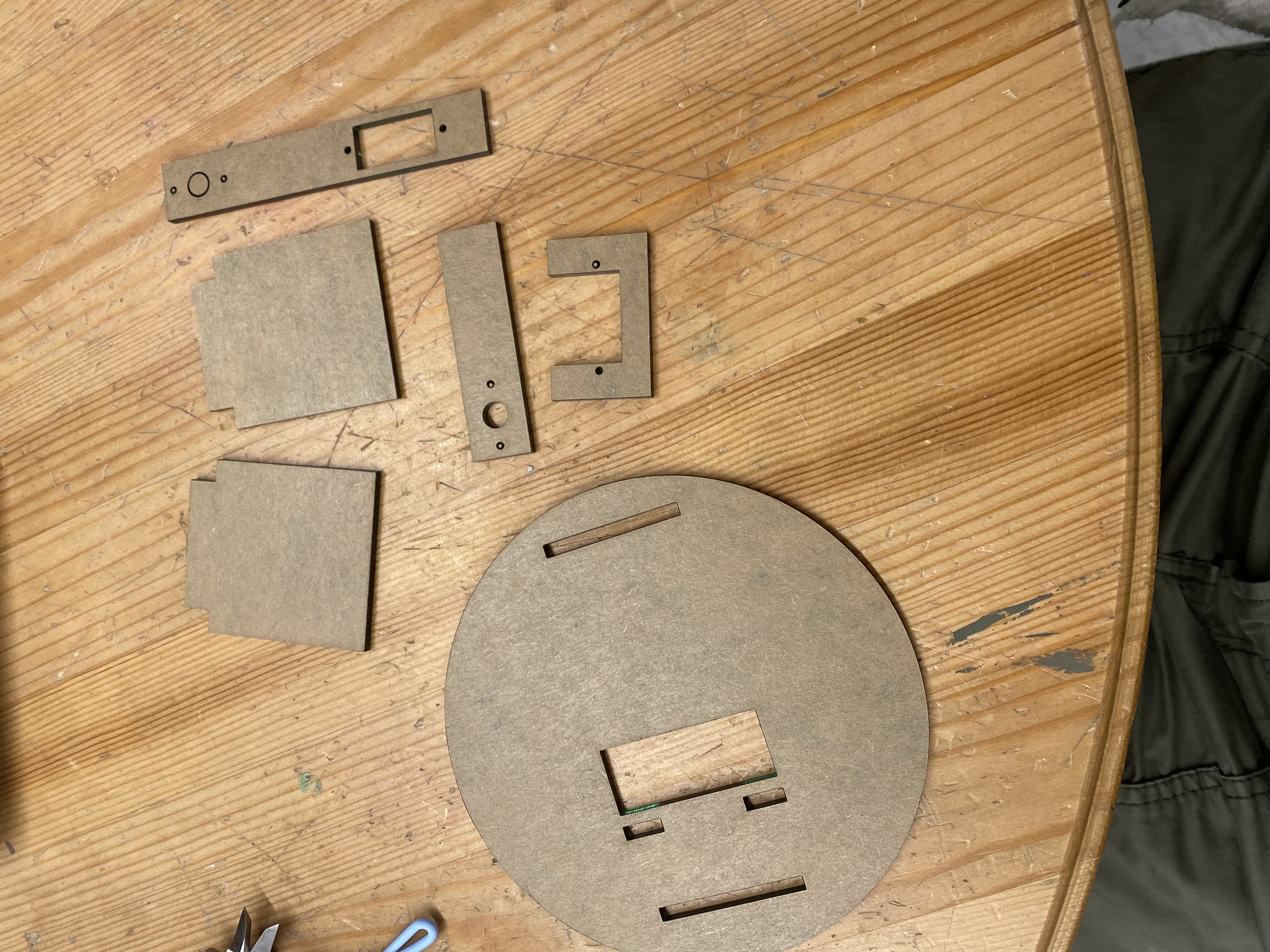
Hour 0.5 - Laser Cutting Time
My first cut was a small fail.
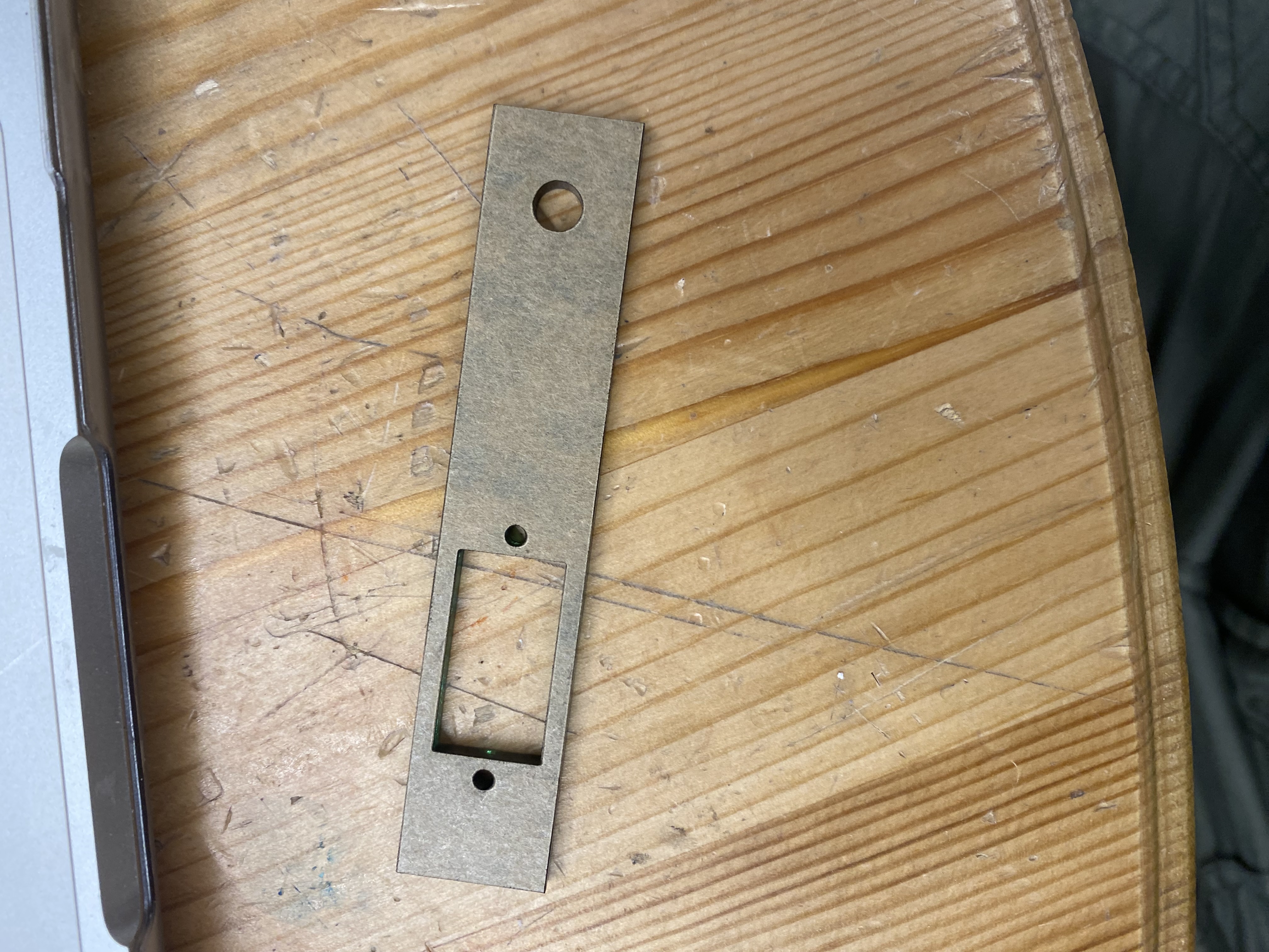
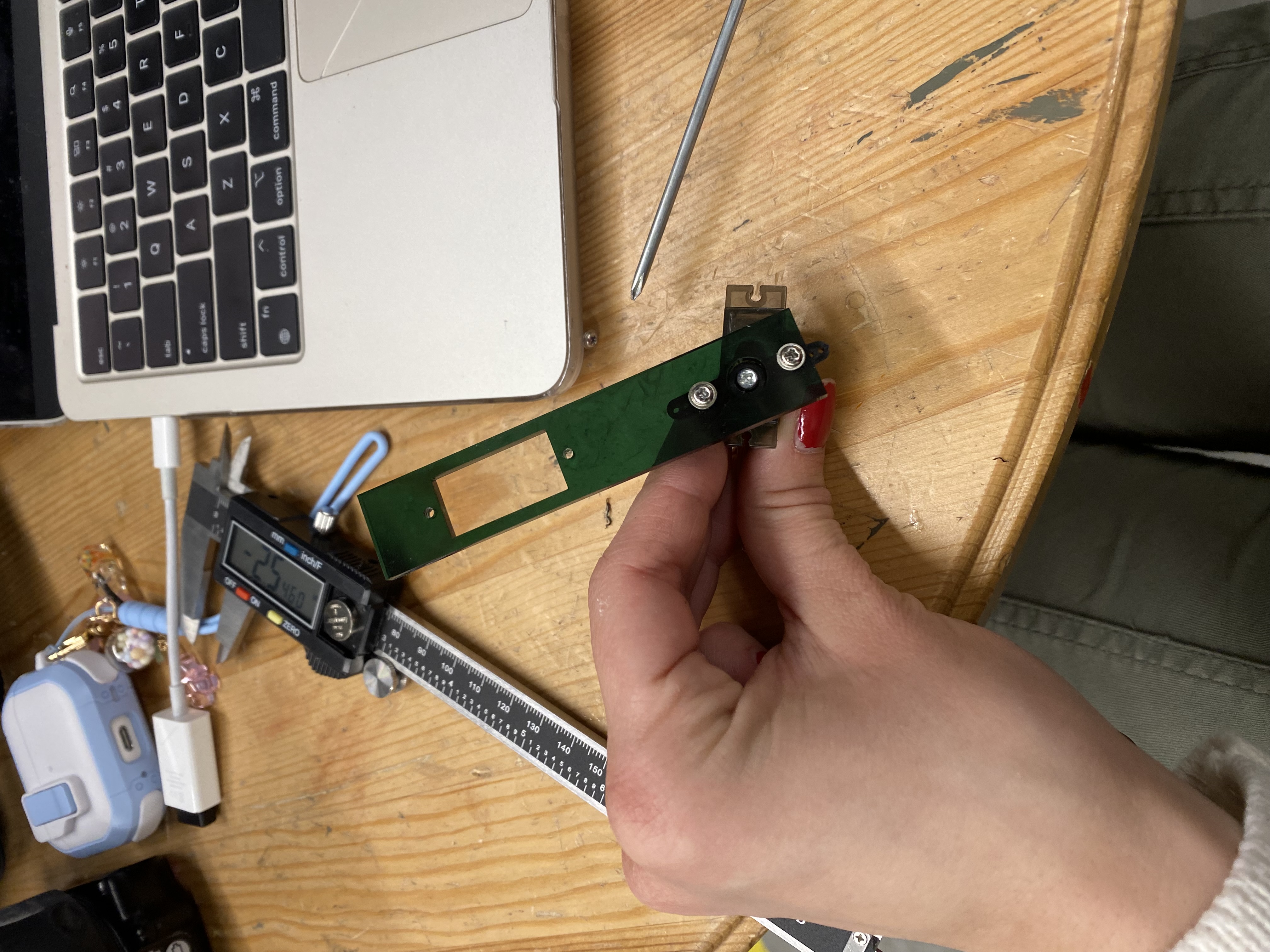
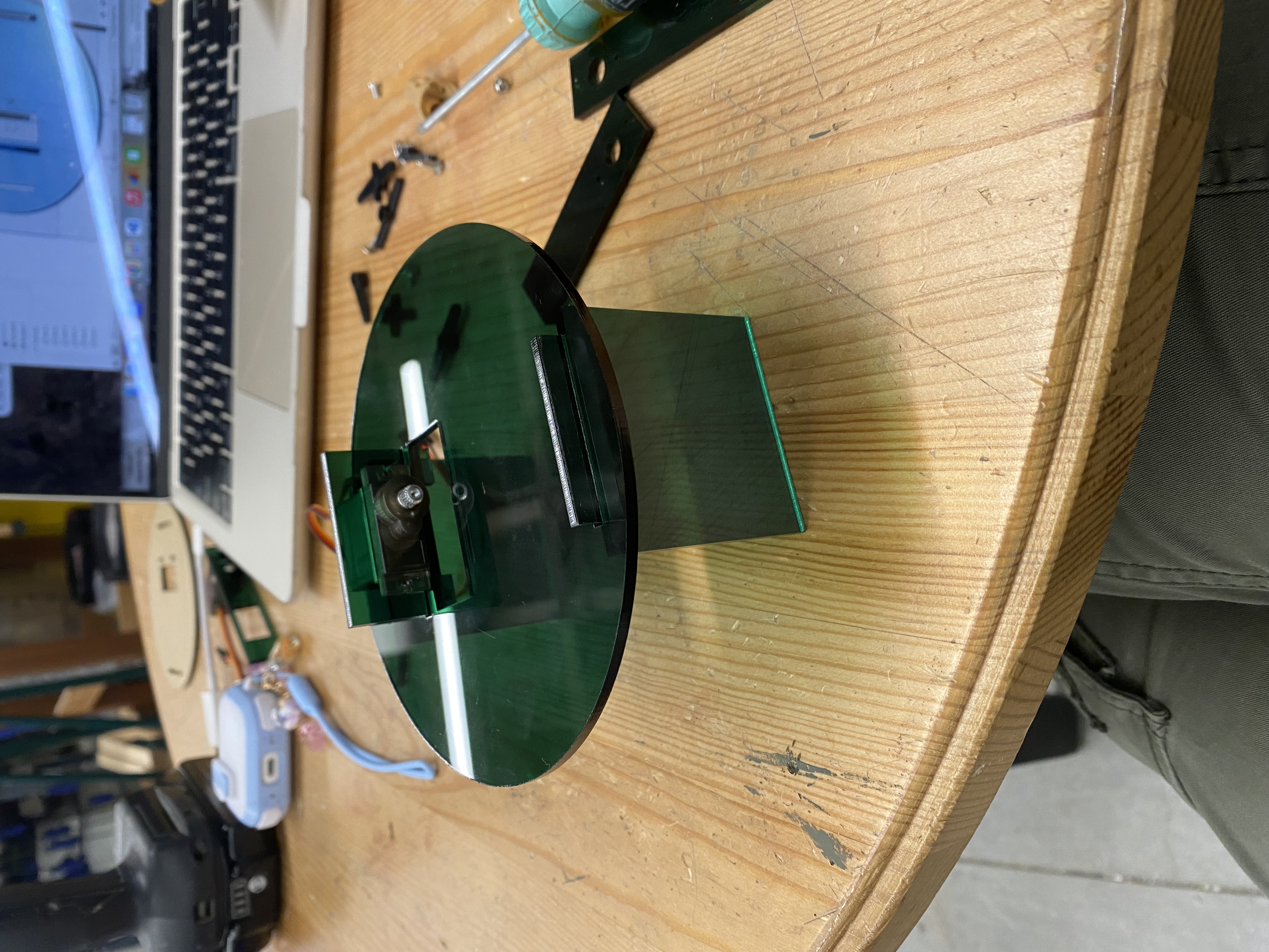
The motor slid in very nice but the screw stripped as I tried to
put it into the acrylic and now I cannot get it out... Change of plans apparently I was usin the wrong screws
so I updated the holes to actually be smaller. Now I have to figure out how to mount the acrylic
to the servo part that actually moves. That will be the next step. I ended up cracking the acrylic because I tried
to put in the motor but there was not enough space for it to pass through with the wire.
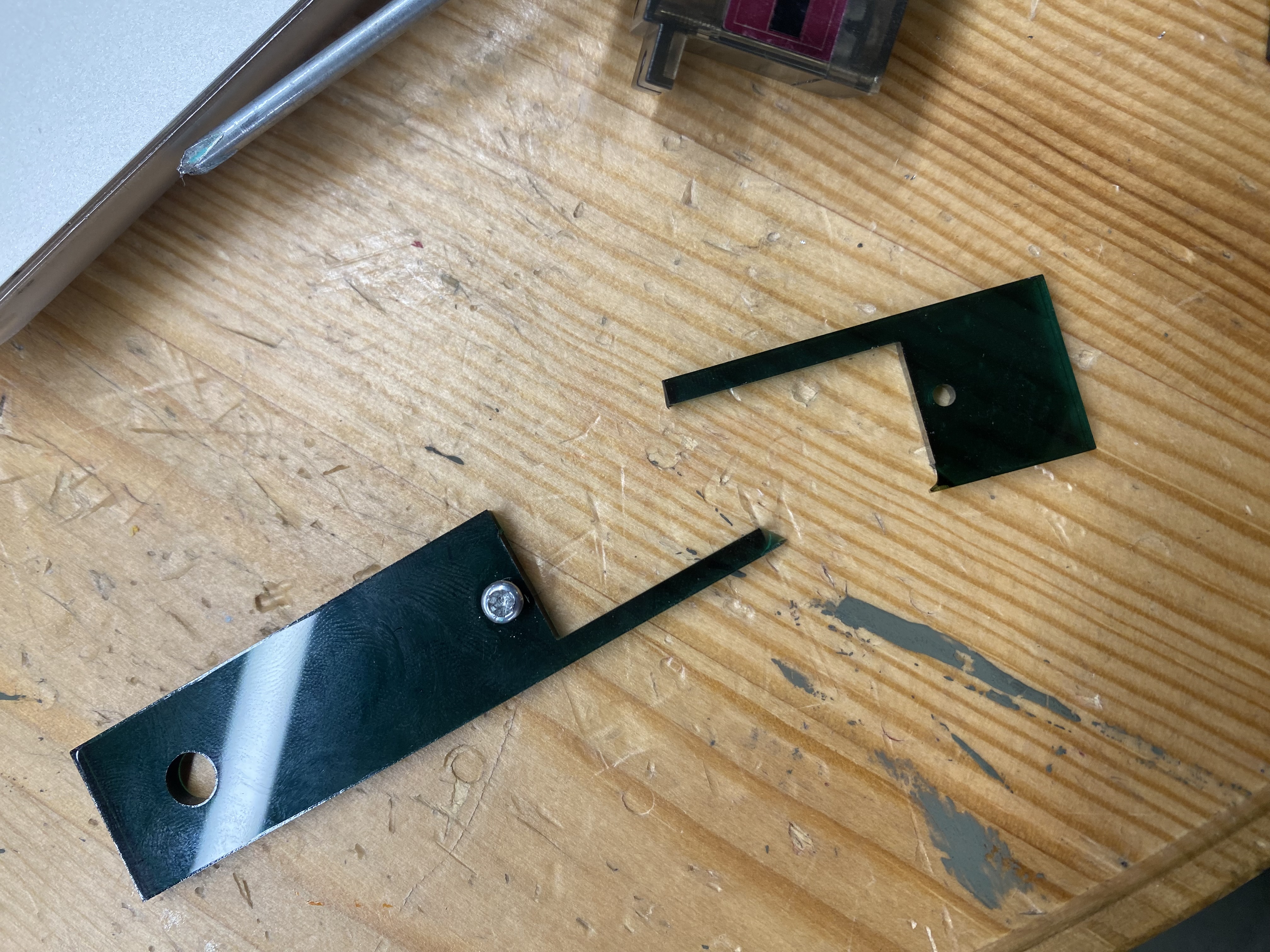
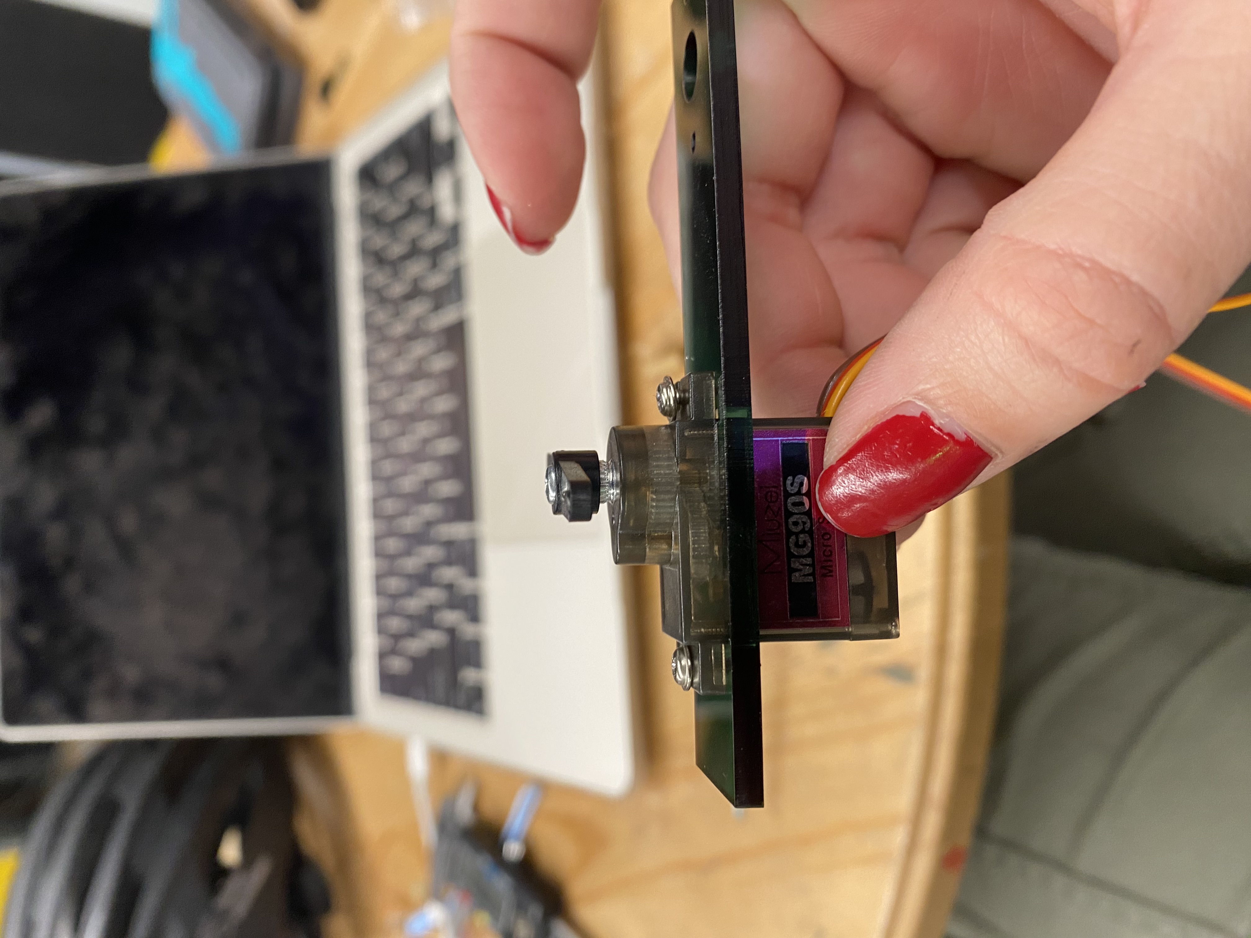
I also found
that I have to put the motor in front of the acrylic otherwise the screw won't hold it to the acrlic because it
passes straight through the motor mounting holes. This time it did work I had to drill out the holes to be bigger
on the actual mount on the servo but it worked pretty well so I am going to go ahead and cut out everything else.
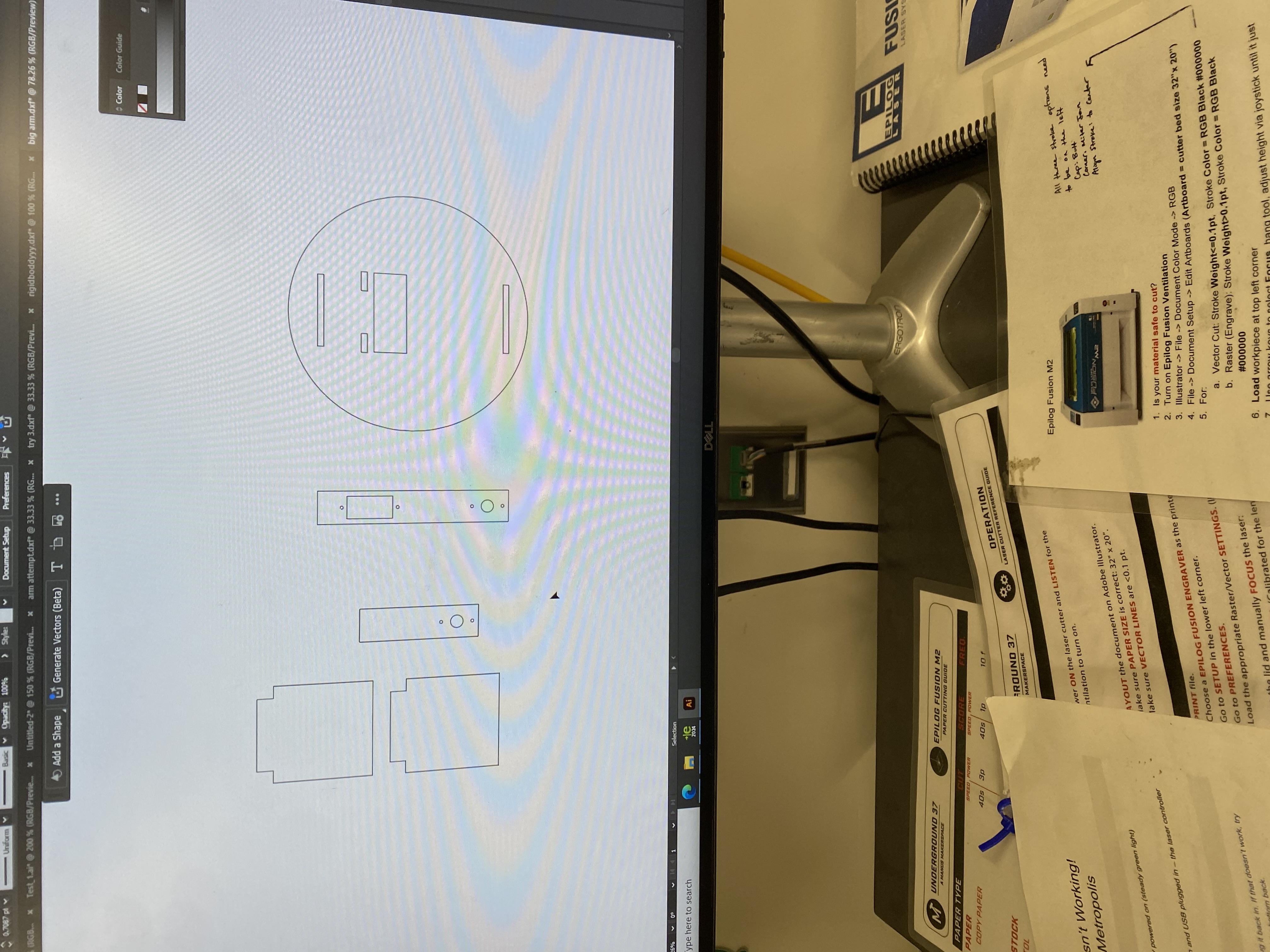
I forgot
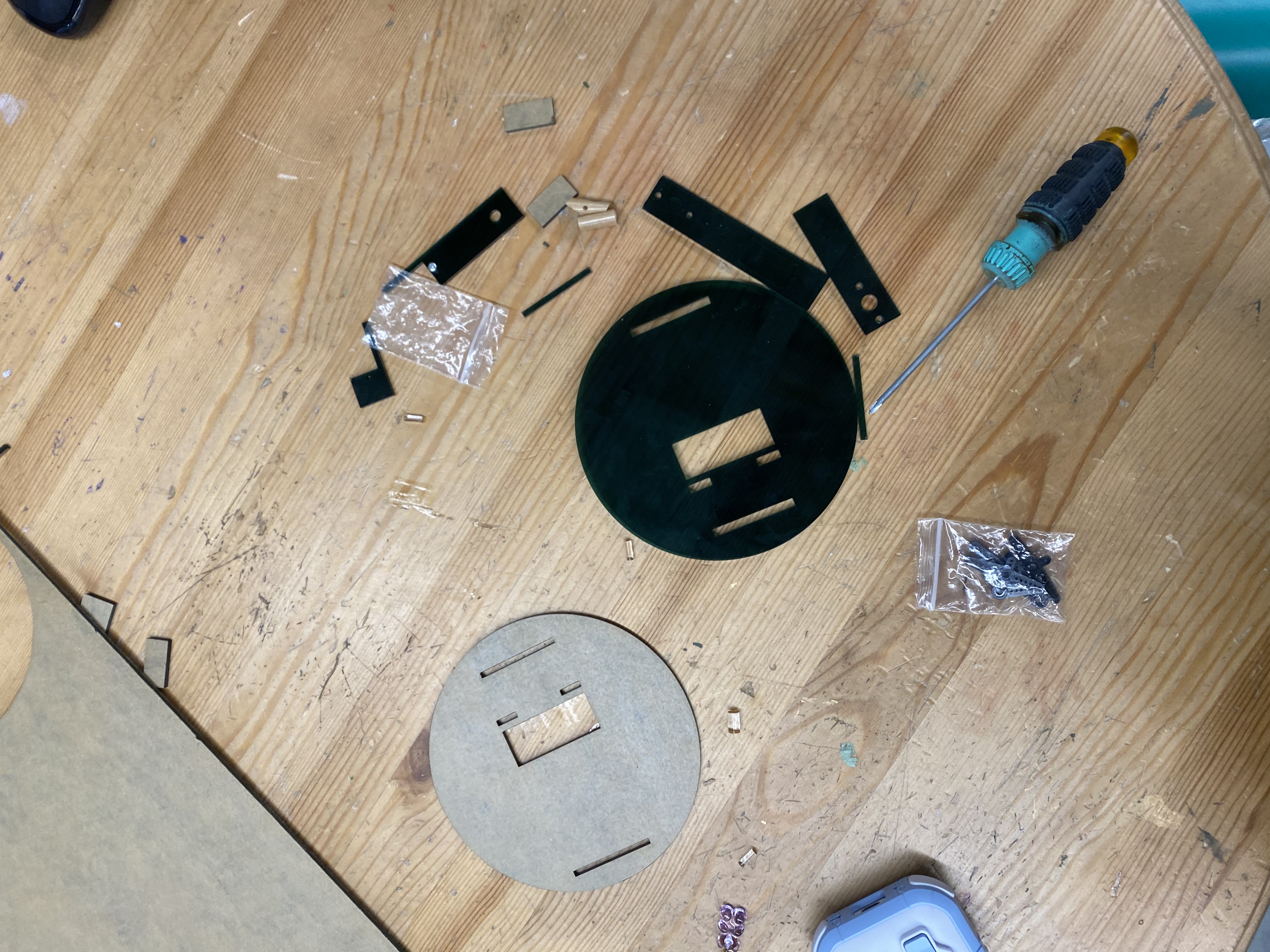
to account for the laser and my pieces are more than a bit wobbly but I think I will just glue
it together. I ended up recutting the circle to account for the kerf and then it was too tight so I cut it again
and this time it did end up working.
I had a small issue where I ran out of screws so I had to run up to edgerton
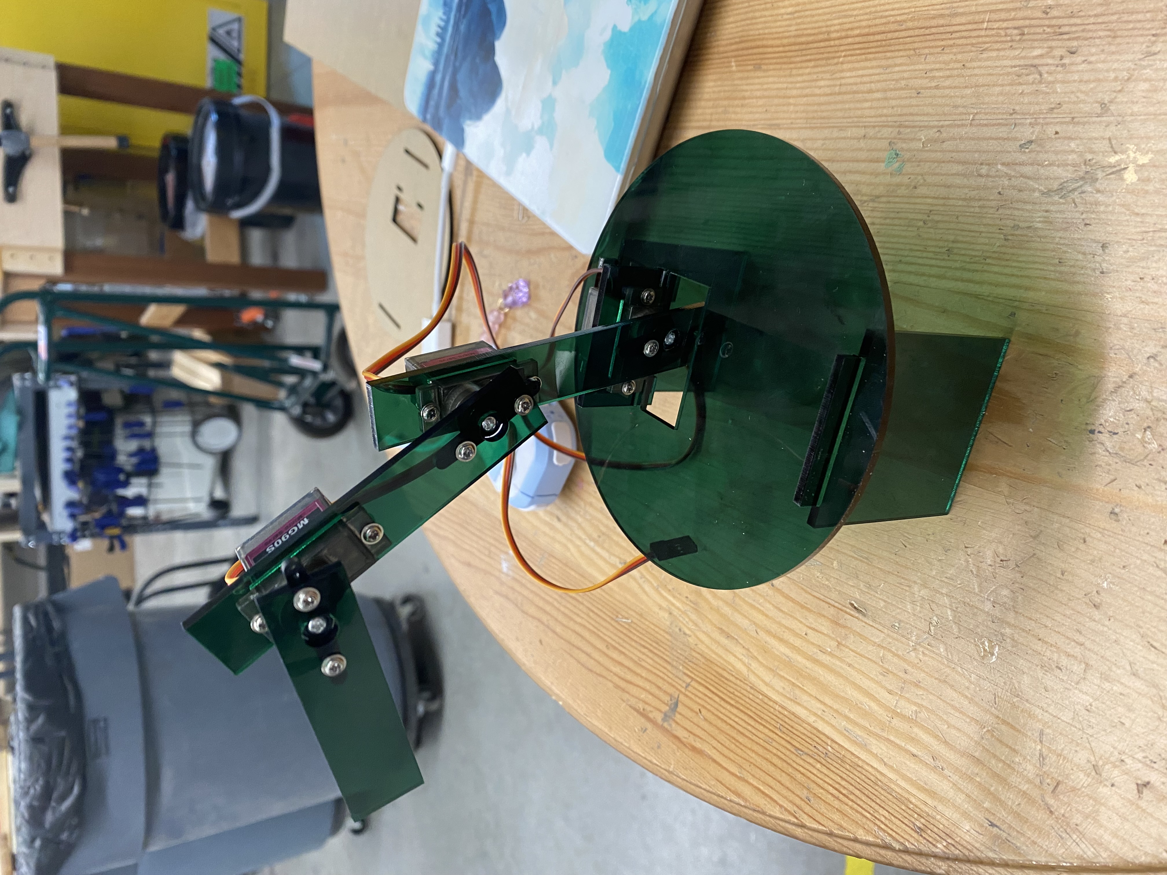
in the end everything ended up working. I wish I had made it a bit bigger to make it look more impressive
but I would have had to run calculations on the torque and overall weight and it seems i reached the limit anyway because
things are starting to bend a bit
Hour 3 - Coding the arm
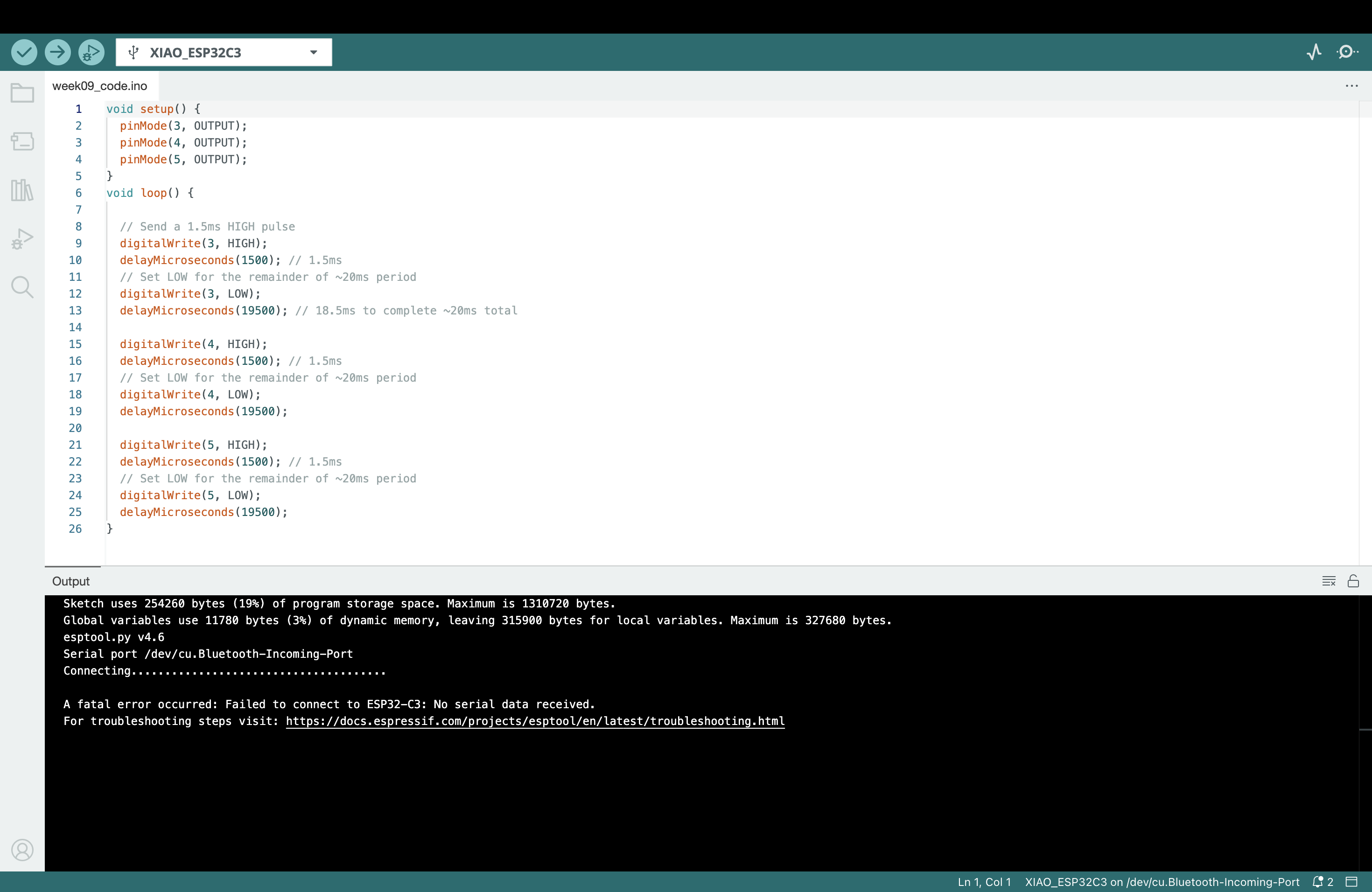
At the moment I will not have time to create an entire PCB for this but I am trying to at the very least breadboard it. I wired it up but i'm not sure i should be directly connection the servos to the same power supply. Okay so this is straight up not working. I keep running into errors about libraries and i don't know how to make it work with servos or even if i have the right libraries. We are mildly aborting and switching over to an arduino nano to see if that works. I was able to add in the library and I think it has potential I ran it a few times without actually connecting it becasue I am in class and it would make a lot of noise. So it didn't work and I had to switch to controlling it using digital highs and lows. The span is from 1-2ms with a total of 18ms with both highs and lows. Each second in that range is connected to a specific location. To test this I can make it pretty easy by making each arm go to a different angle.
Hour 4 - PCB
I initially tried to wire a breadboard to see if I was doing it correctly
but apparently XIAOs and breadboarding is a bad idea because it has a very loose
connection.
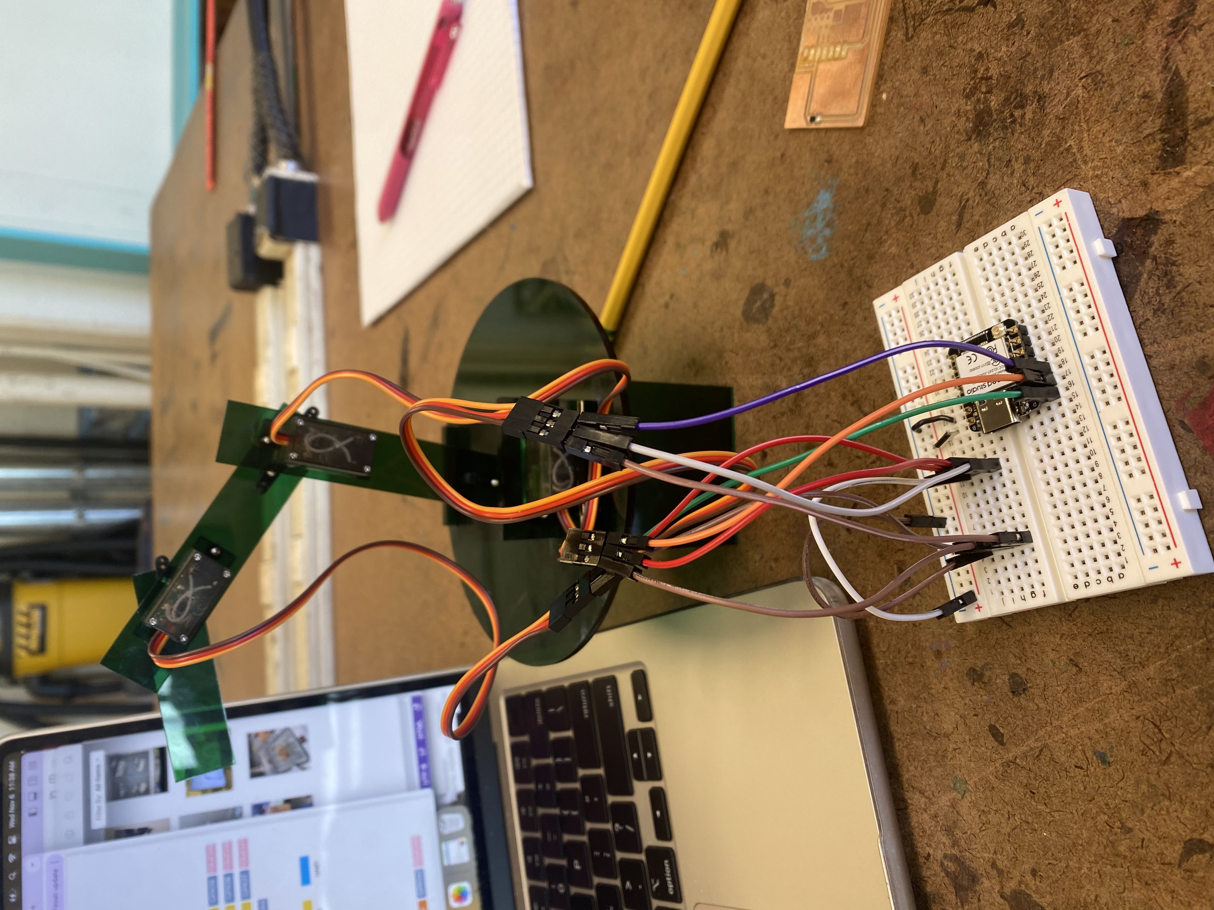
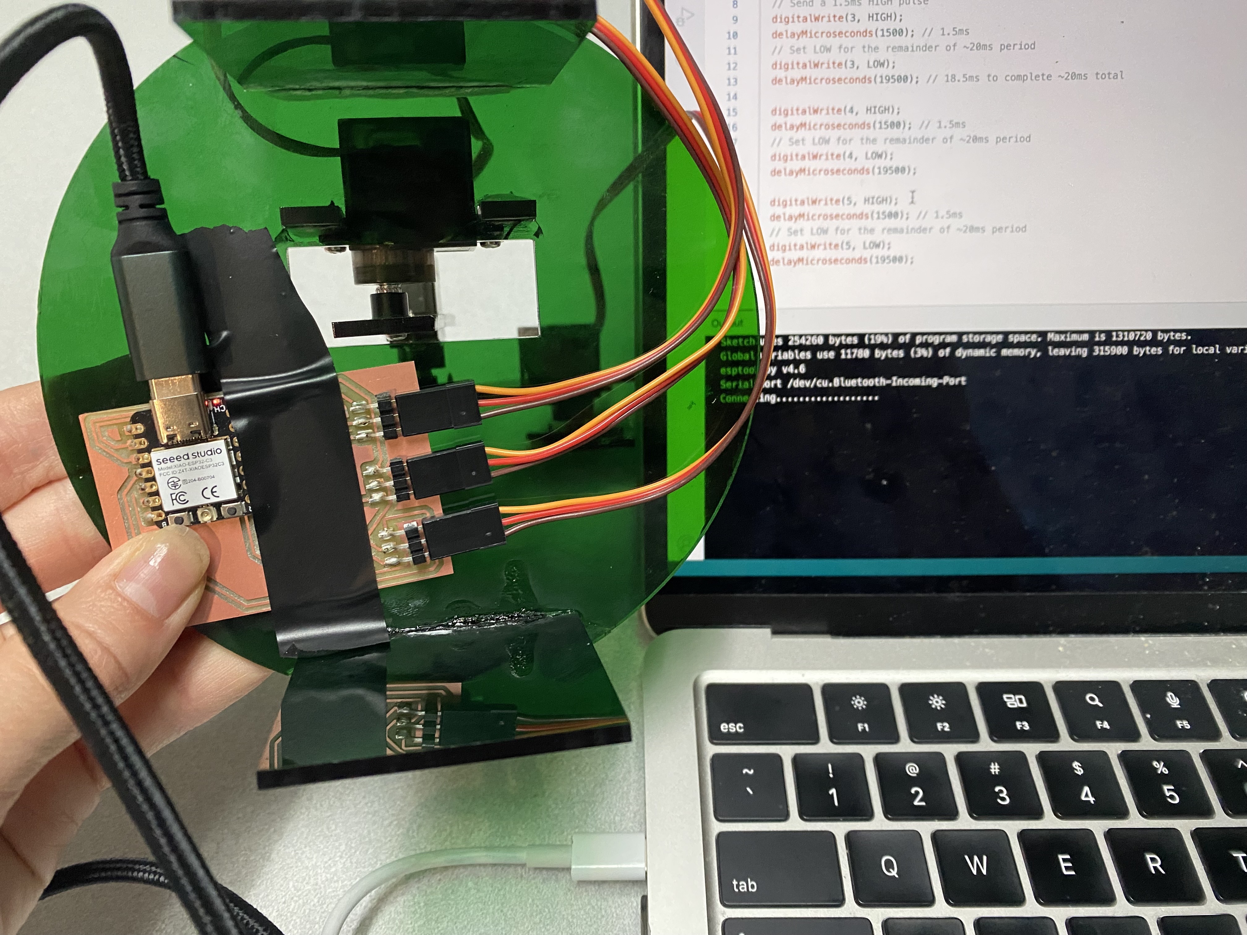
I created a PCB using the seeed xiao esp32c3 and three horizontal header pins but the esp32 was not turning on which
was confusing so I tried to take it off and switch it but no matter how much I desoldered it didn't come off so apparently
the issue might be that the headers are actually touching the traces so I tried to desolder the headers and the whole copper
trace peeled right off so now I have to remake the whole PCB. I was able to remake it pretty fast since it is really
only three headers.


Integration
Now that I have the physical, the code, and the PCB it is time to put it together and make sure that it all works.
I have had a few issues including dropping the physical arm twice but thankfully the glue made it come back
stronger than ever. Yay so guesss what its that SAME error of serial not found and I switched cables, used a hub,
did a boot, did a reset I just don't understand why I keep running into this and worse I have no idea how to stop \
getting the error

