Documentation
Brainstorming Designs
We started early last week to make sure everything went smoothly. During the first meeting (which was like four hours long). We decided on our project and divided into teams, created tasks, a timeline, and overall decided on an idea. I am currently in charge of the motor and pulleys section of the machine. We also have a grabber block, coding , integration and documentation, and frame and bed.
Motors and Pulleys General Design
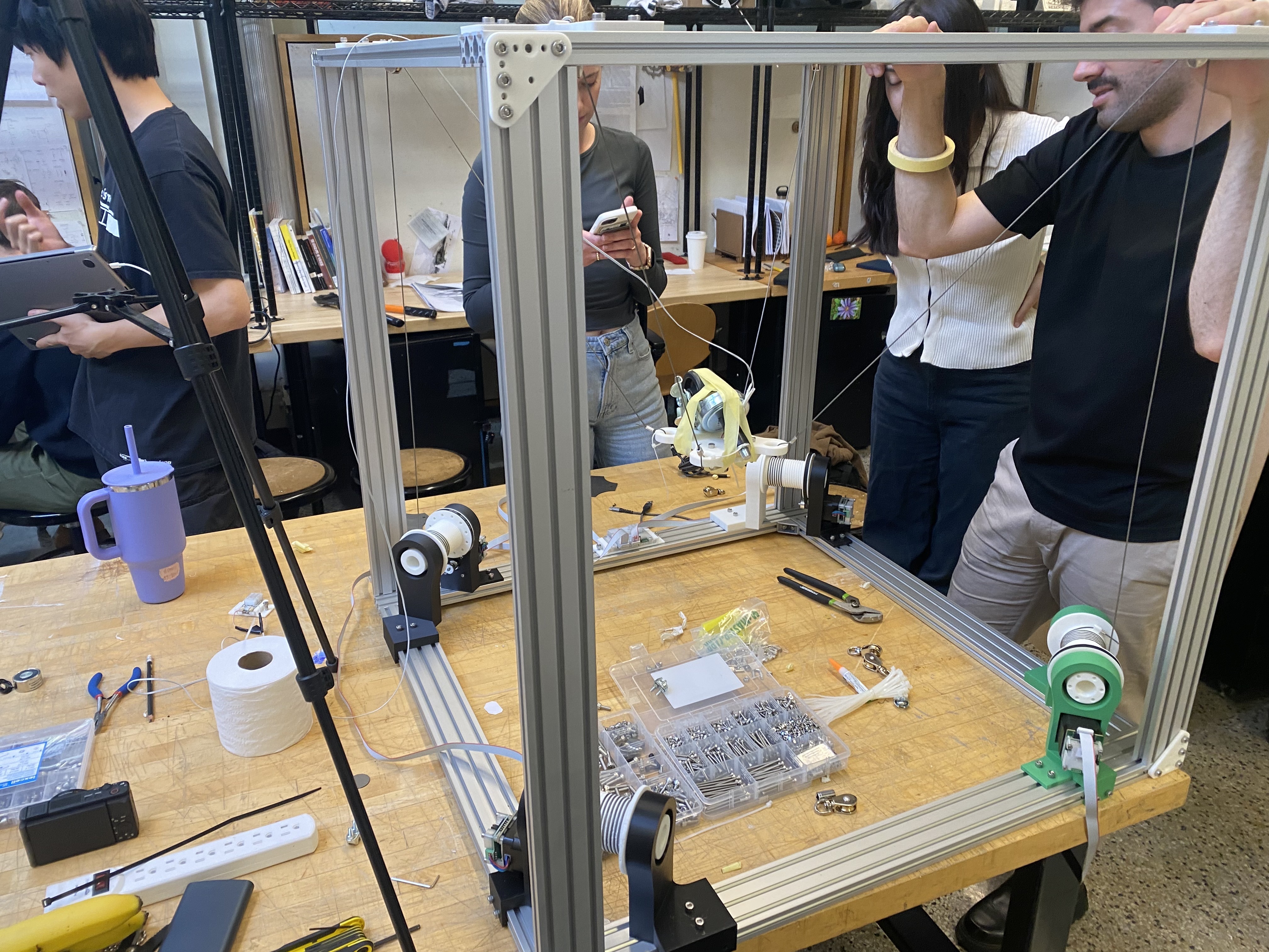
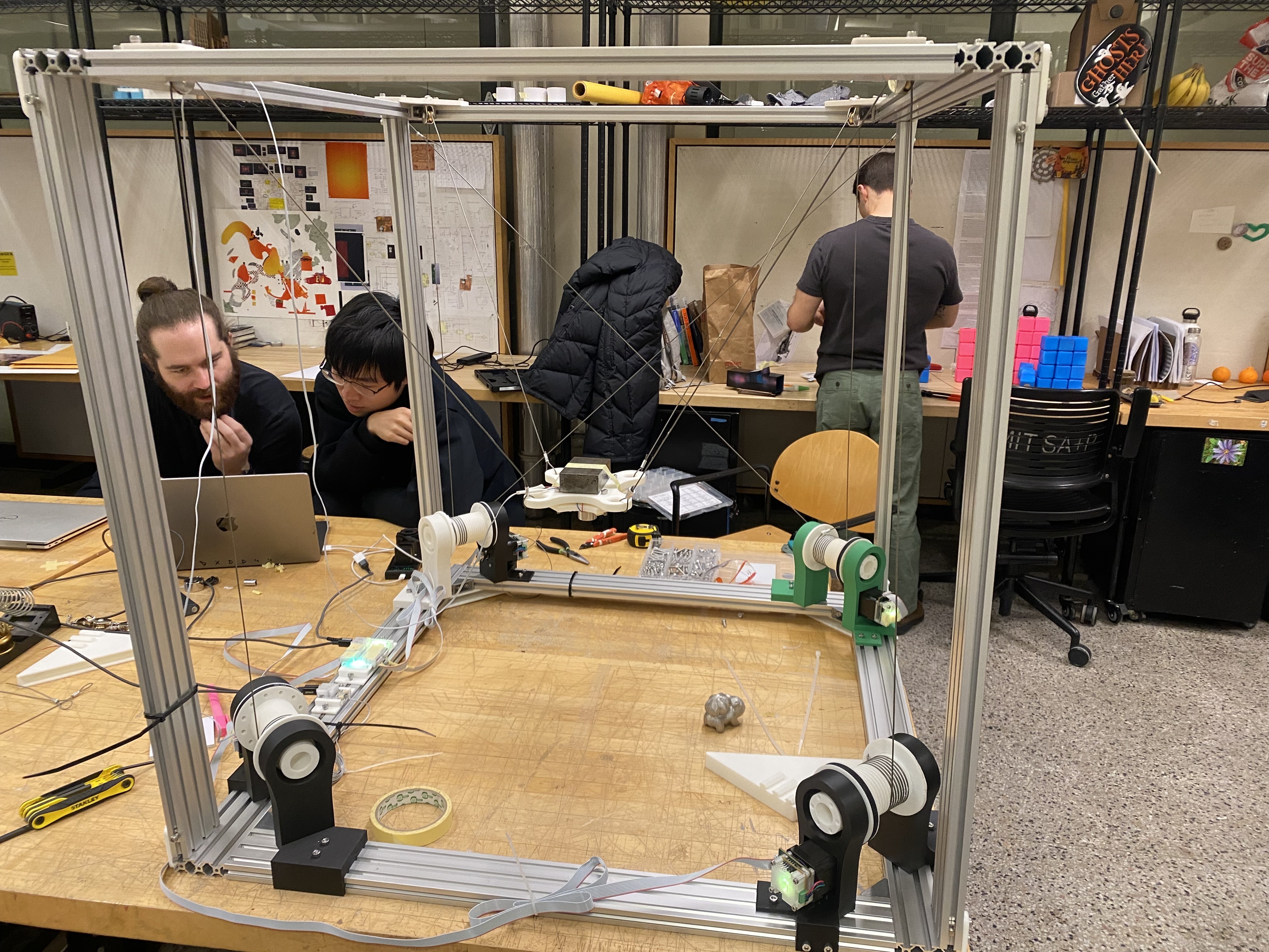
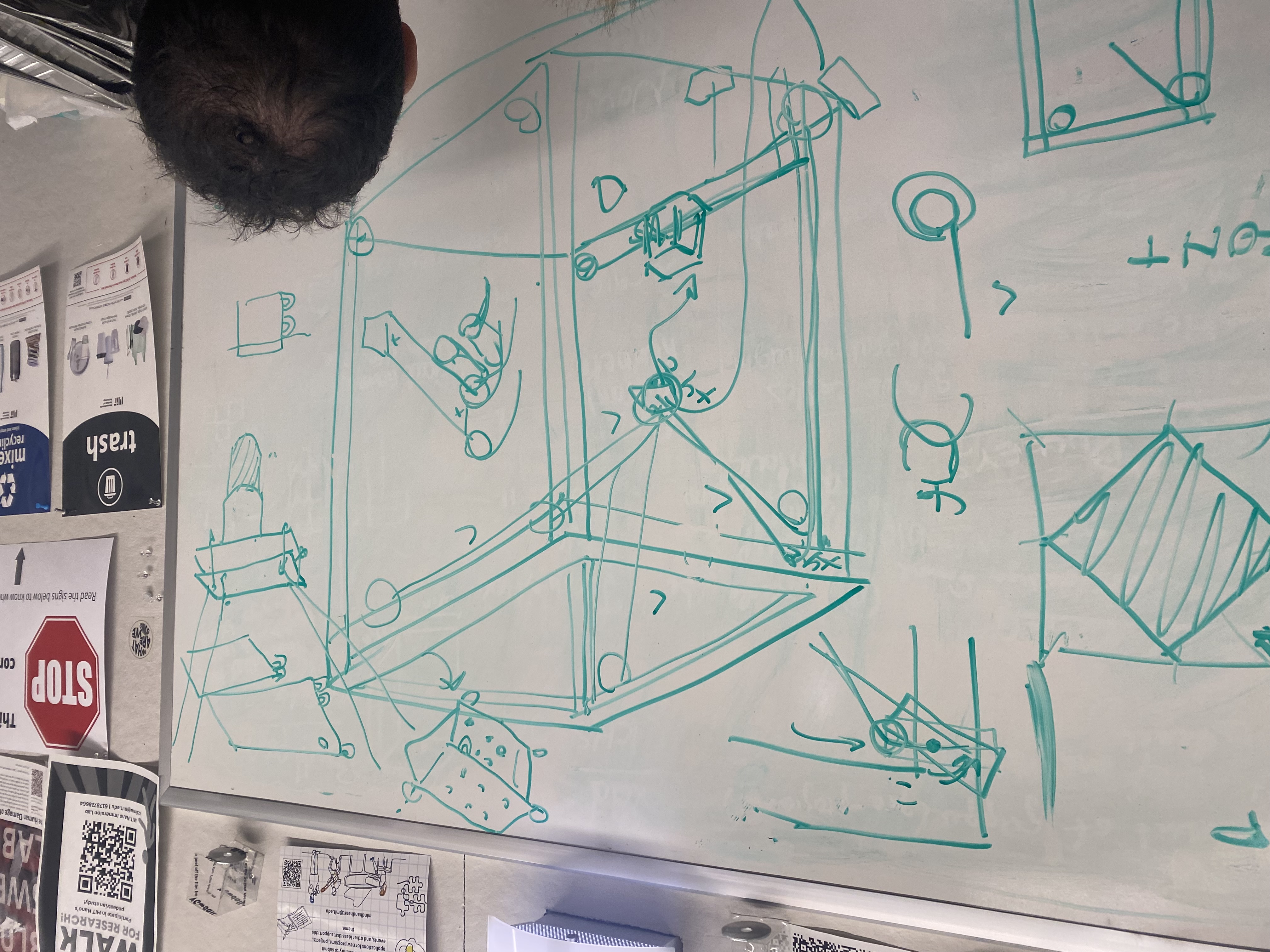
The way that the motors and pulleys work is that there is going to be four that each attach to the corner and the griper.
There is going to be an idler in each corner that holds the wire and curves it down into a winch which spools it.
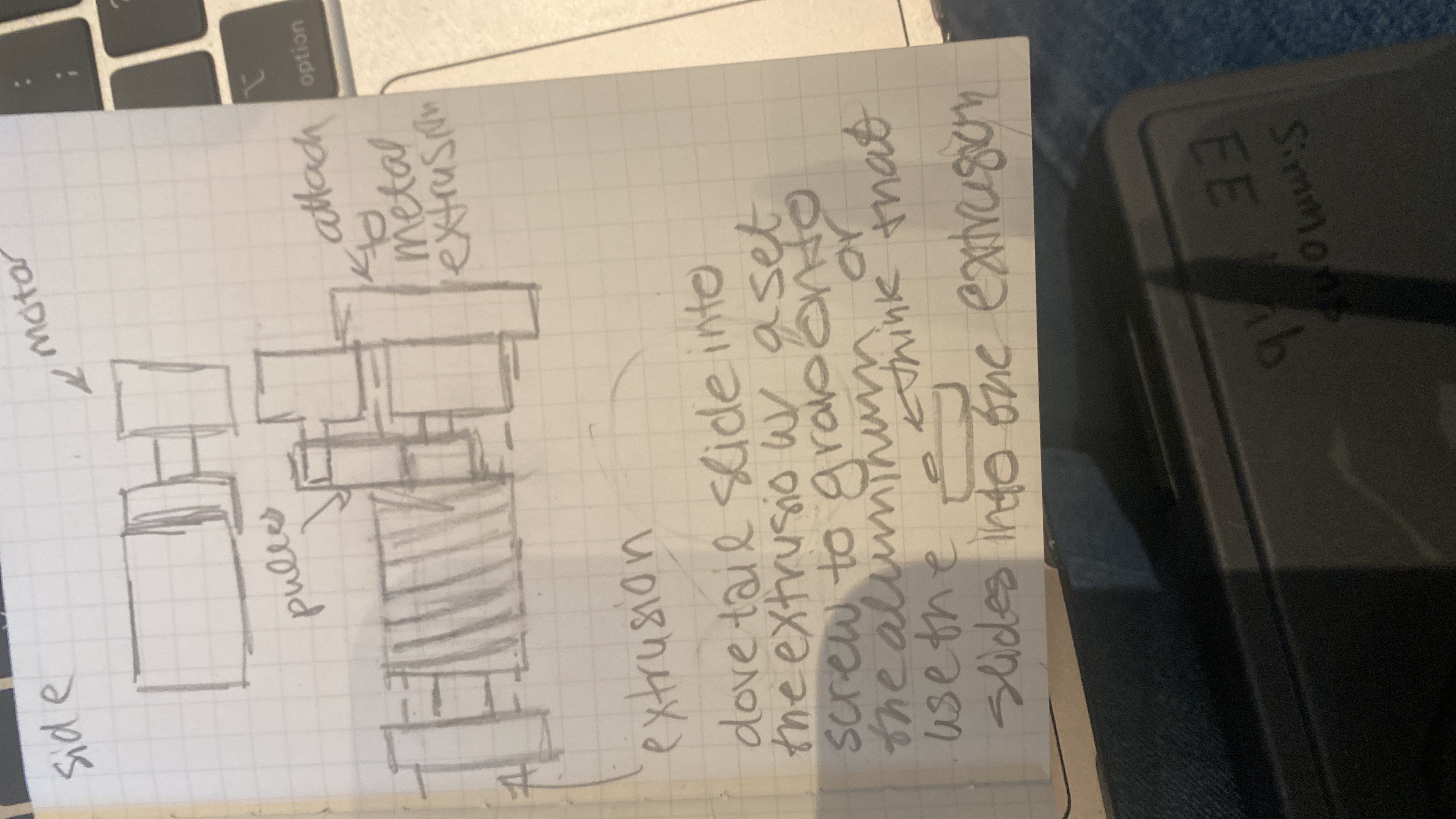
The spool is attached to a pulley which is attached to the motor via a belt. I went to OH (which was part of our
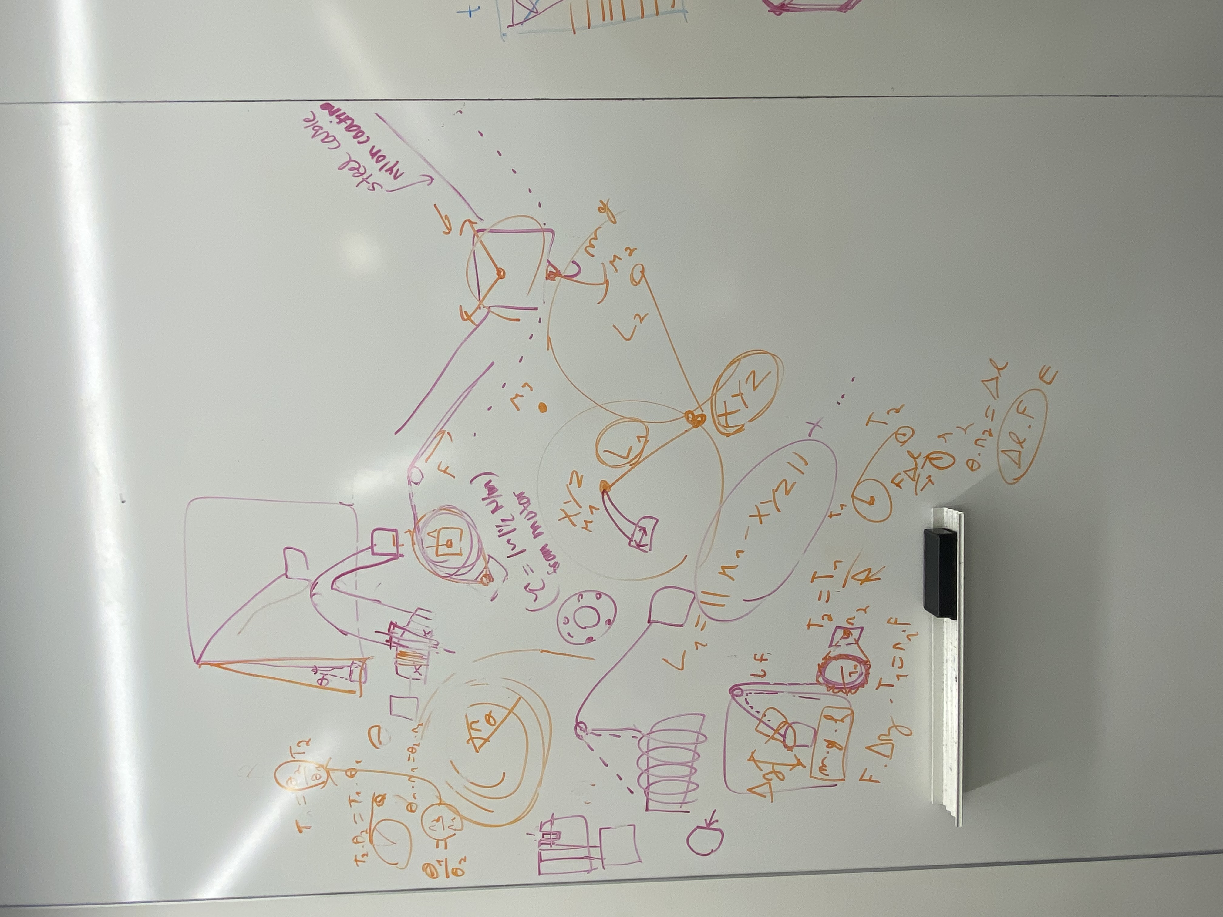
really long meeting). After speaking with quentin I was able to work out most of the physics. The tension in all
four cables sum to the weight of the gripper. That tension then will go all the way down to the pulley and the motor.
With that you can calculate the torque given the pulley torque equations. However, since the gripper is going to be
so light we should be able to use the motor without any problem. There would also be an issue with calculating the
length of the string if the winch was near the top because there would be an angle which would change length as you
spool and unspool but as you make the winch further away the small angle theory will come into play and the length
will not change that much.
Motor and Pulley Meeting
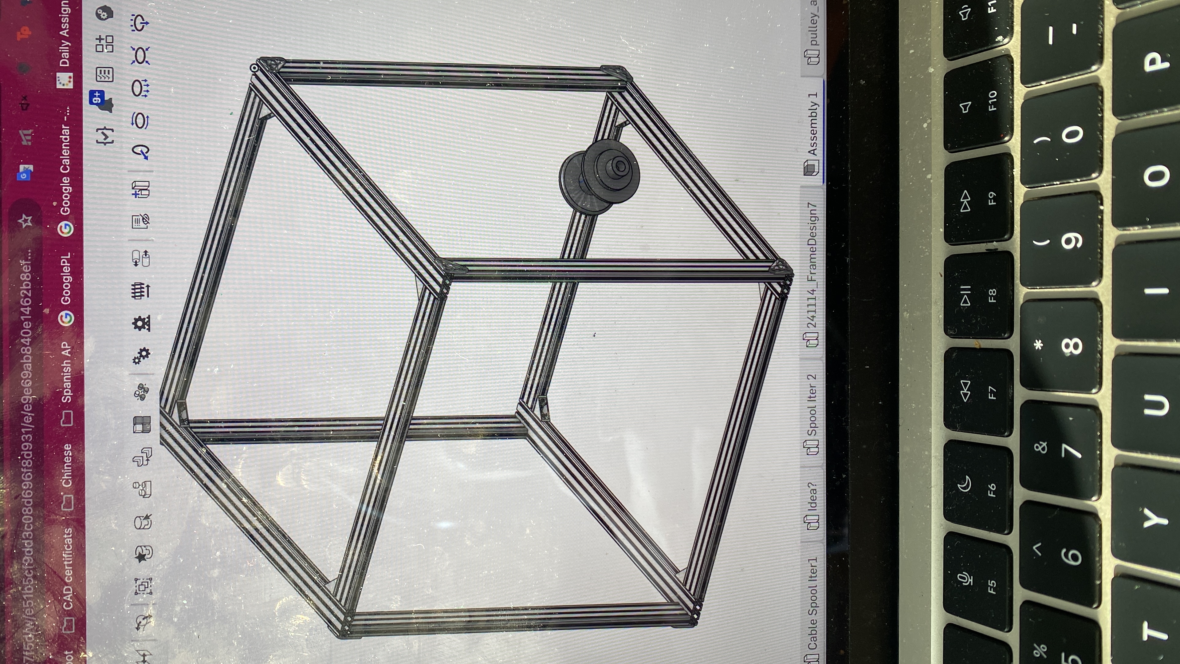
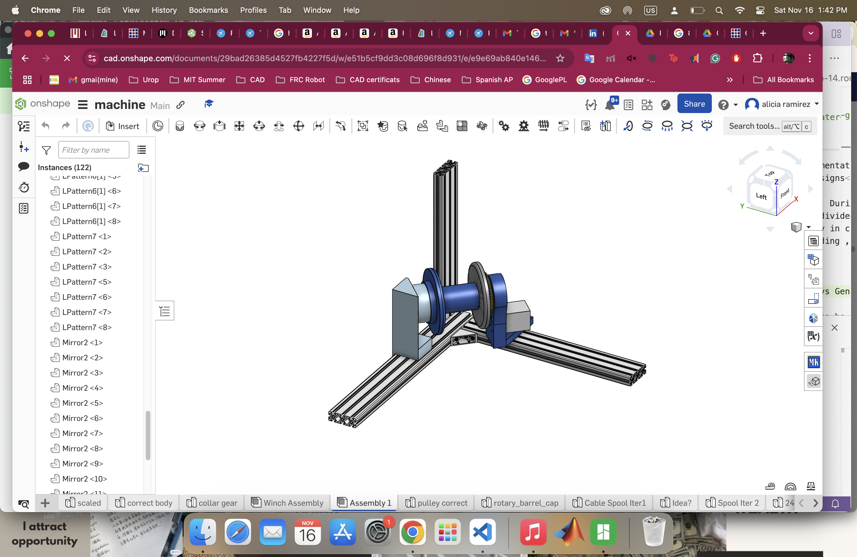
We had our first subteam meeting. Both of my teammates weren't able to make it to the meeting so I was keeping them up to date as to what the design decisions had been made. We then broke down tasks. I am in charge of attaching the spool to the motor and to the frame. Our first iterative design was a spool that would fit into the holes of the pulley. I then realized since were 3D printing we might as well literally attach the spool to the pulley and create one thing that takes care of everything. We also talked about how to attach the idlers at the top which is now Yutian's job. The design is made to fit into the corner of the frame so now the winch design also has to be diagonal to the frame. The reason for this is that making the four motors in each corner allows us to play with the entire surface of the bed instead of a triangle or a rhombus.
Motor Holder Design
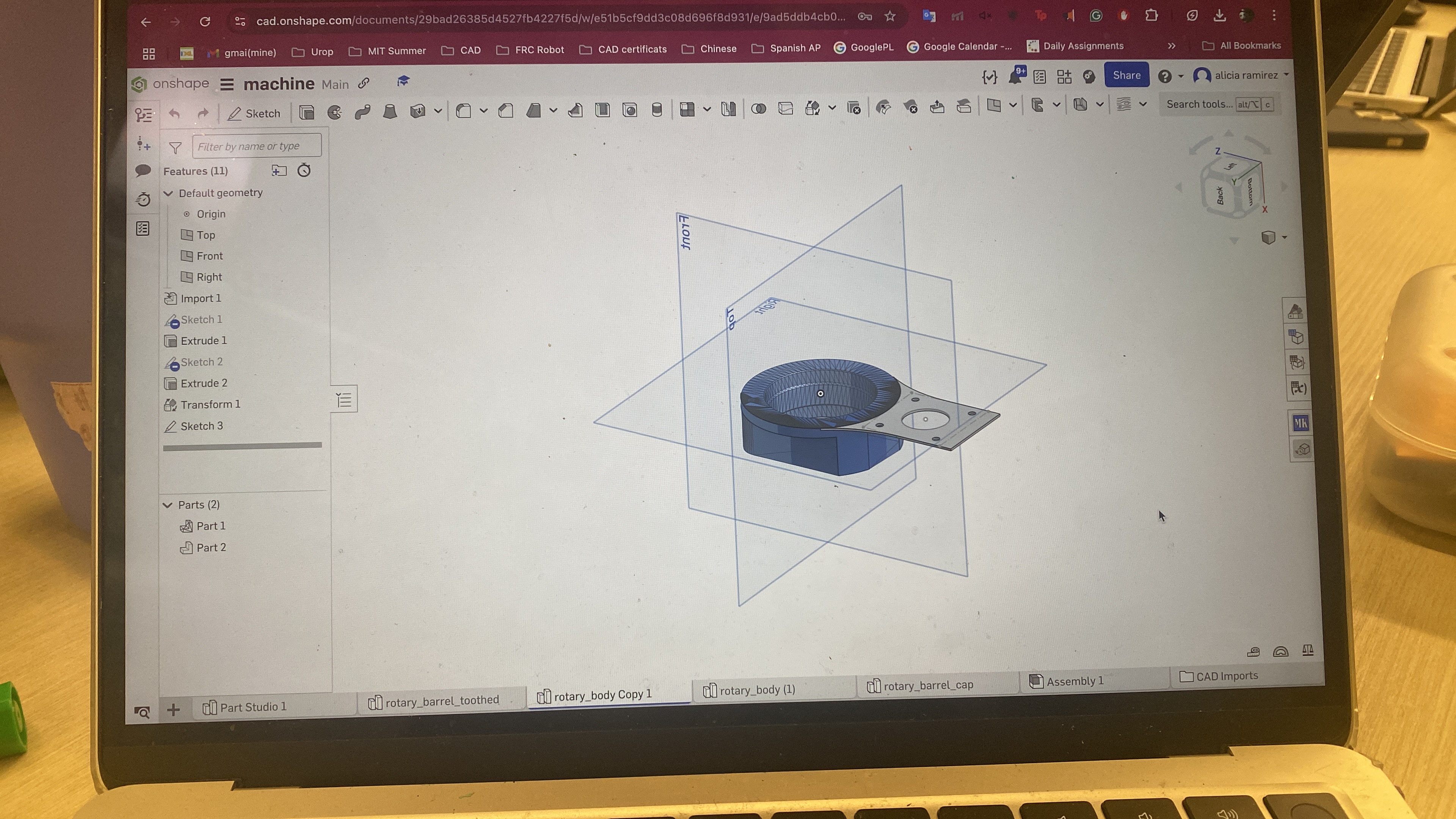
It is now my turn to start CADing. I like the way the bearings fit into the design they gave us so I'm thinking about just taking
that and adding on to the rest of it. But I also don't like working with STLs. I think I'm going to give myself about
an hour to attempt with their CAD and if it isn't working ill switch over to designing my own bearing holders.
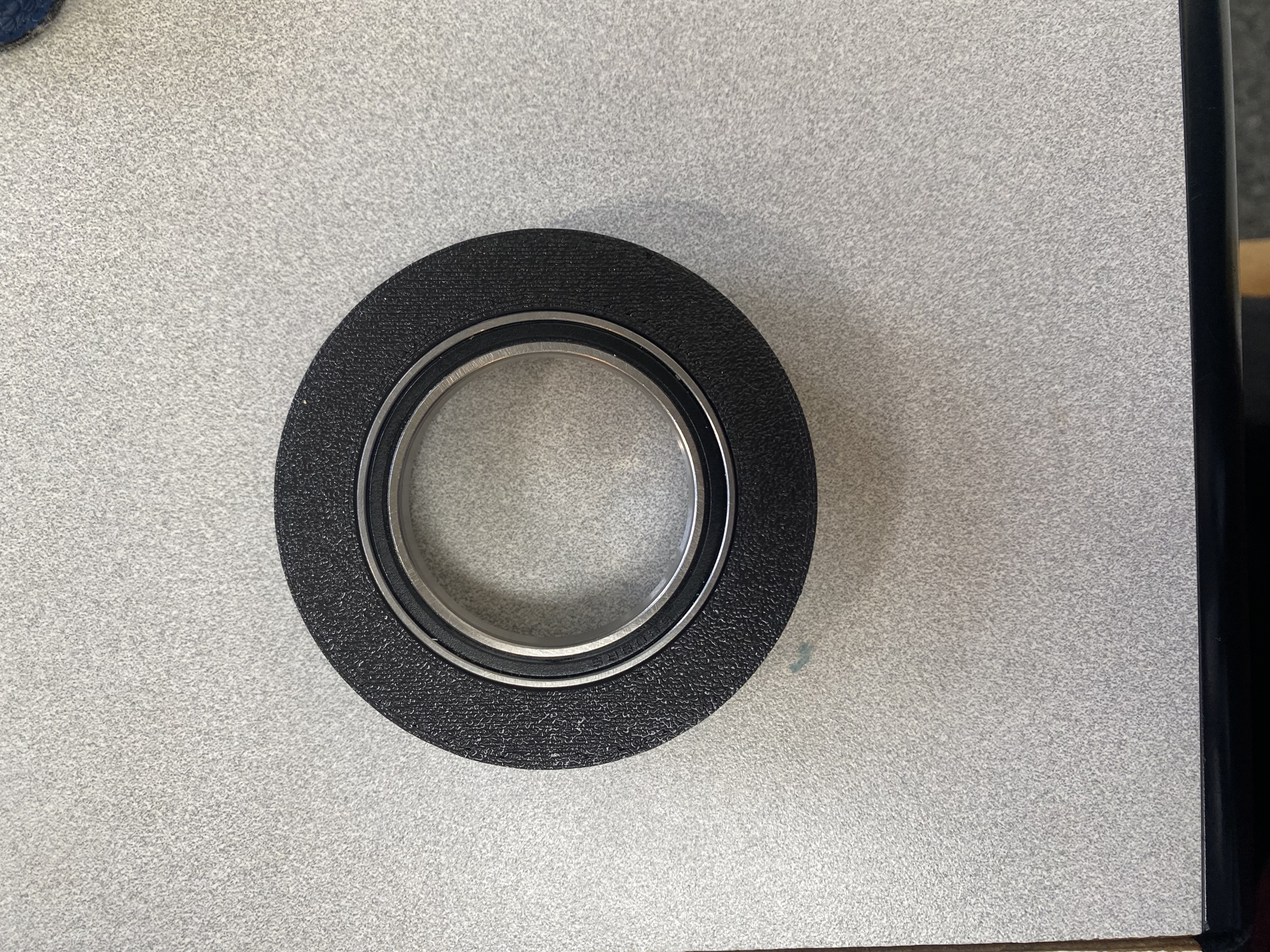
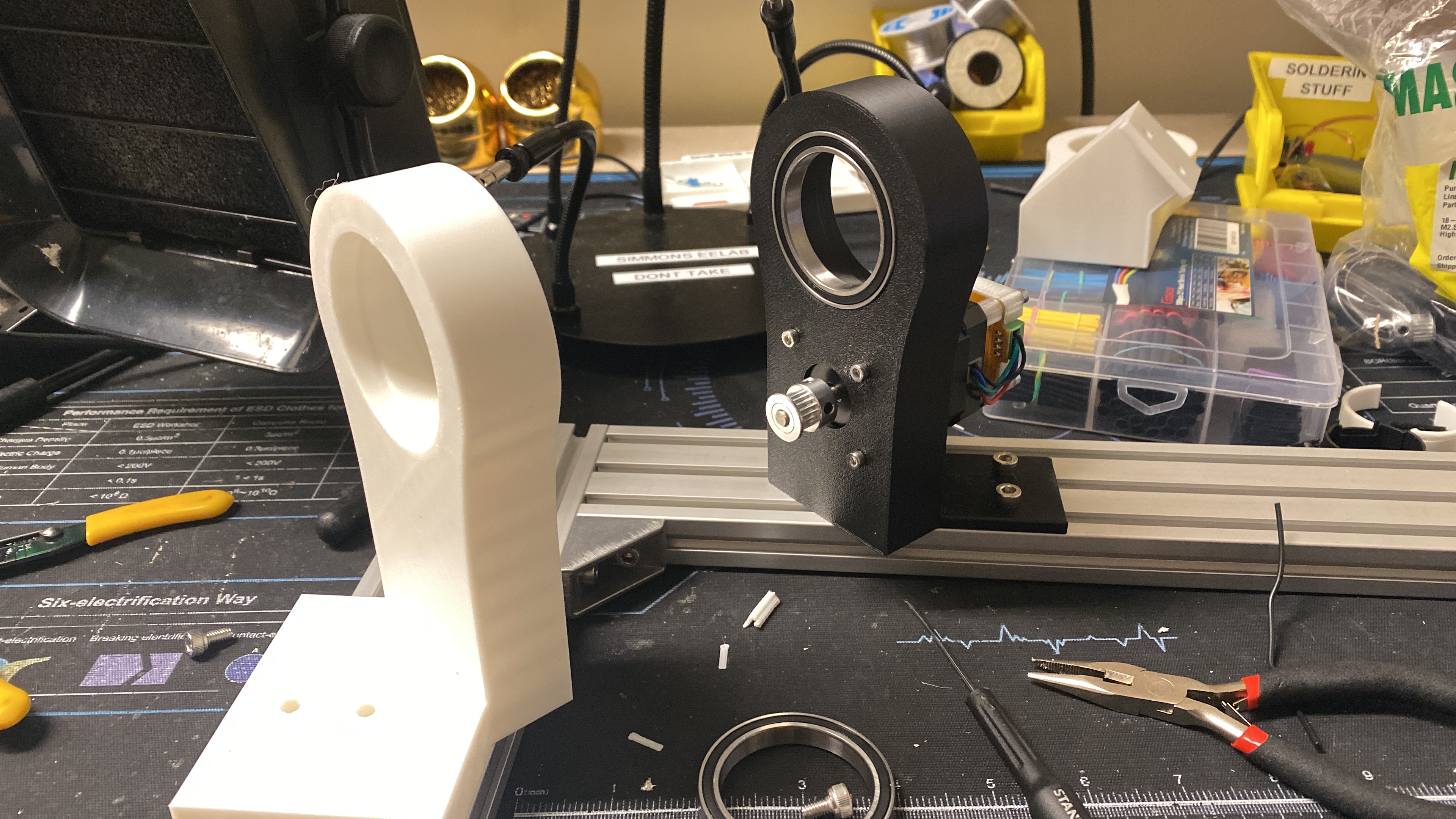
I actually ended up tracing their bearing holder and now I am sending it to print to see if i got all the dimensions correct.
The next thing I am going to tackle is the distance between the motor and the pulley center. I finished printing the bearing
holder and it fit so well that the bearing won't come out anymore. Now that I finished a general assembly with the spool and the motor
I have to figure out how to attach it to the actual frame woo
Attaching to the frame
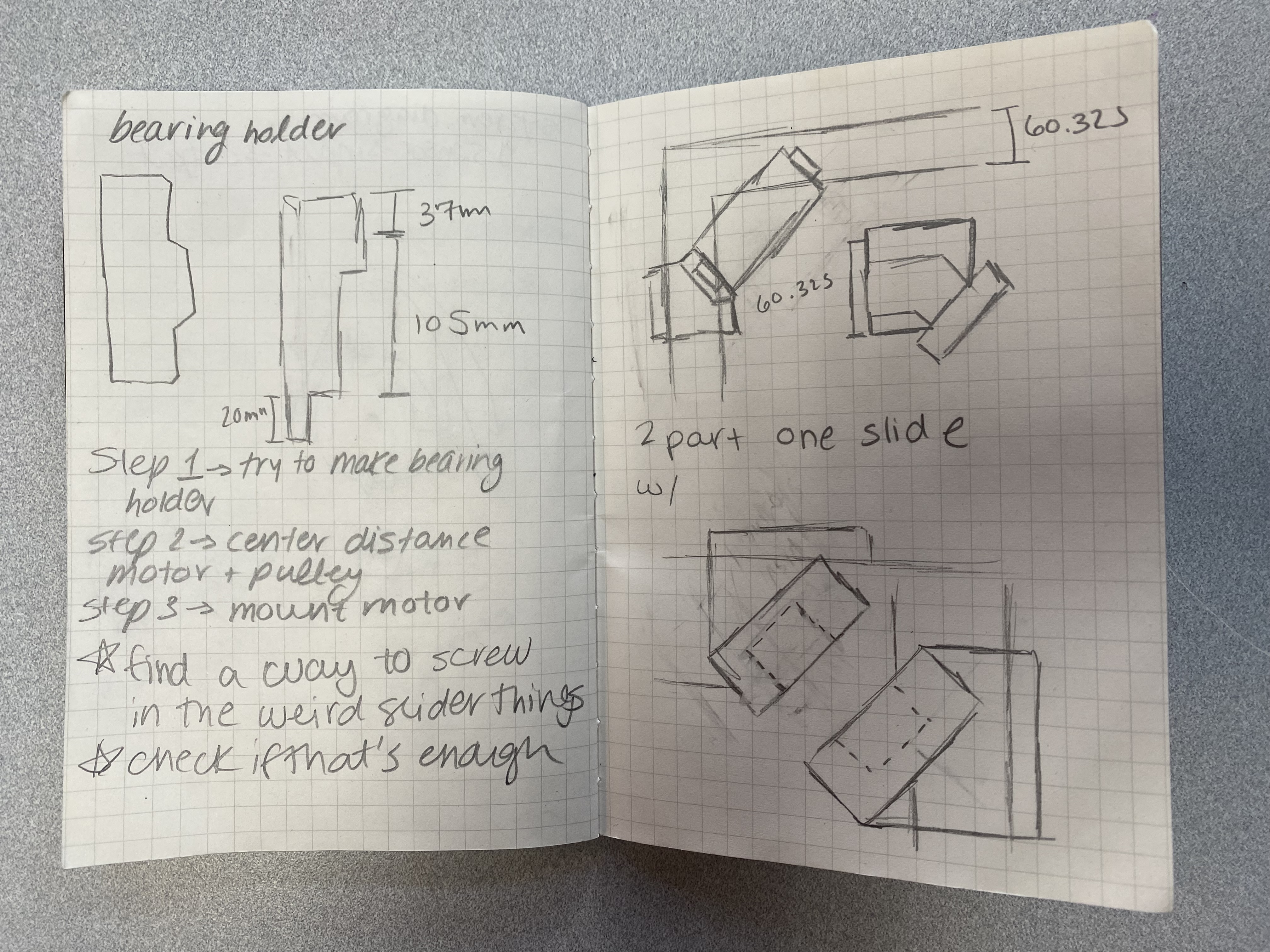
I started off with a few simple skectches I wanted it to have an overhang onto the side where I could use the little slider
pieces and kind of just screw the mount down. I was able to design it in a way that also mounts to the top of the 2x2 frame.
The design is prety simple it slides across the base bars and will screw down to the correct distance always placing the
spool at a 45degree angle. I designed one side with the motor in mind and the other side does not have a motor. I started doing some
test prints and they came out really clean. In the second iteration I want to have something holding the motor so that not all
the stress is on the bolts and then I would also like to add another anchor to the frame. Apart from that I made a few tweaks to
the spool including an ending for the wire and path for it to fall in. I am putting everything to print and praying for it all to work.
Test Prints
I started my two holders to print like thirty minutes ago and just realized that the spool is way too big for the mini so now
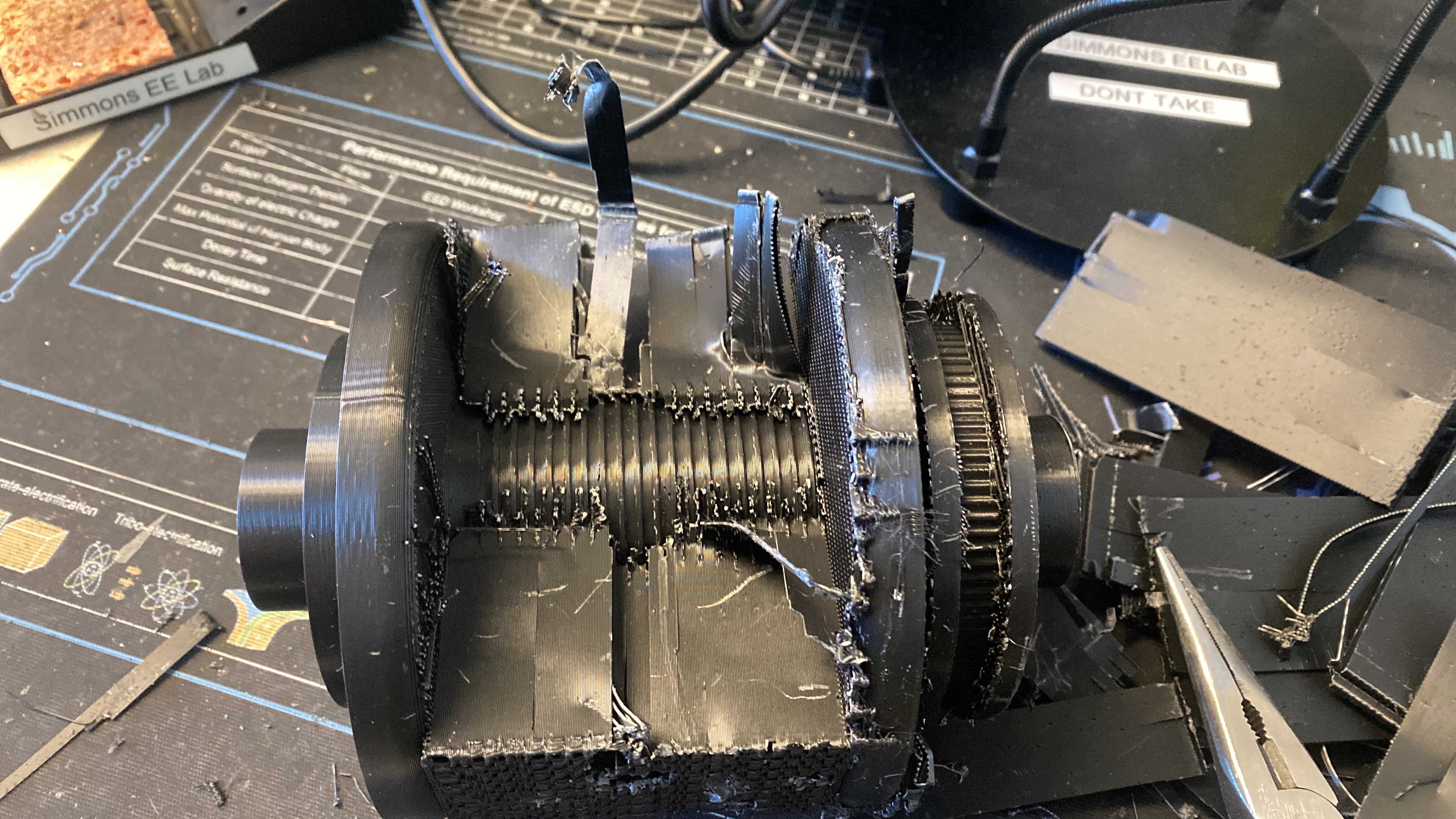
I am trying to take a bit of height off and praying that I can print it all. I was able to print it and thirteen hours later I started taking off the supports
that took roughly an hour to an hour and a half.
Integration
Today we are doing the group integration and the winch is not working. The pulley on the winch is scaled incorrectly and the
pulley does not fit on it.
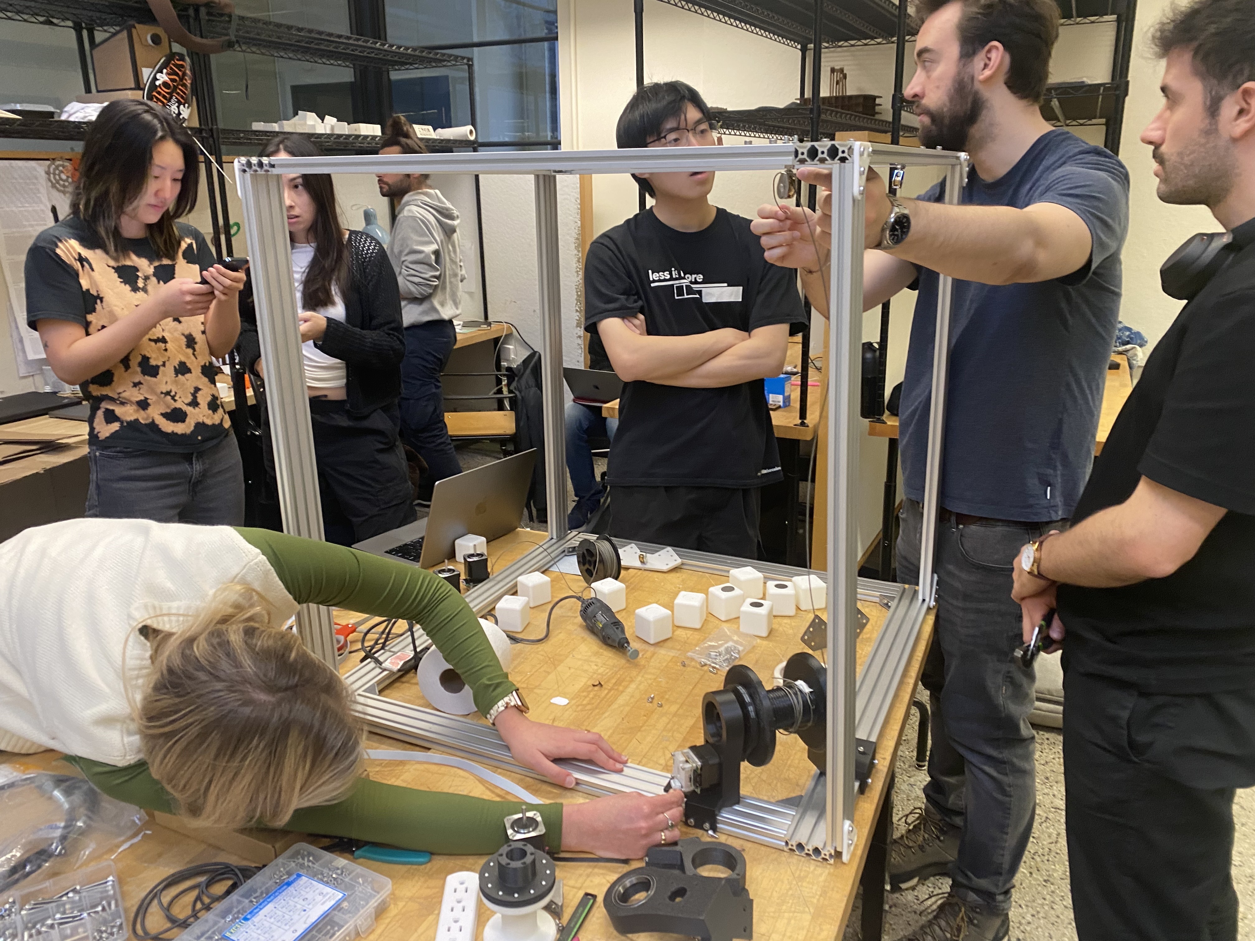
We have to redesign it but the spool that holds the rope is working and is the correct diameter.
There were a few things that we ended up redesigning on the spool. For one it is not as big as the first iteration. We also
have the pulley scaled correctly and a lip for the bearings so as to reduce friction. I also added in a new time of termination
for the screw apart from that one that we already tested. I sent the four spools to print and now instead of 13 hours
for one print it is 18 hours for four of them. This also probably has to do with the fact that I changed the type of supports
and also the orientation allowing it to print faster, all this apart from the fact that the design itself is smaller.
Update unfortunately the four spools I printed did in fact not print. I showed up at edgerton 17 hours later to see
that some glitch occurred and that it had been printing but nothing had been coming out of the extruder.
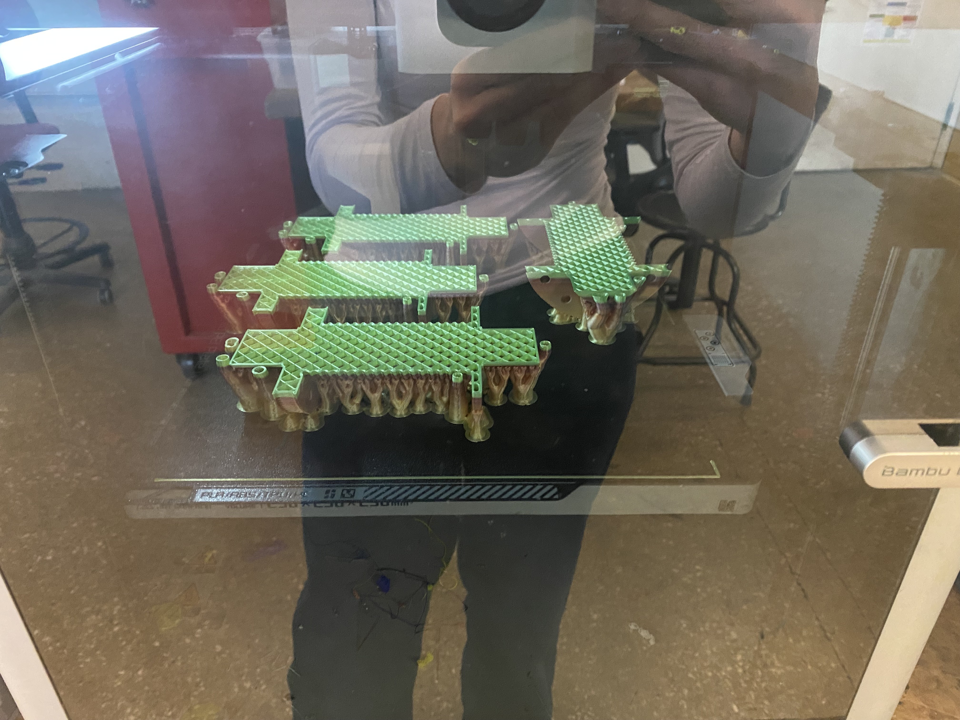
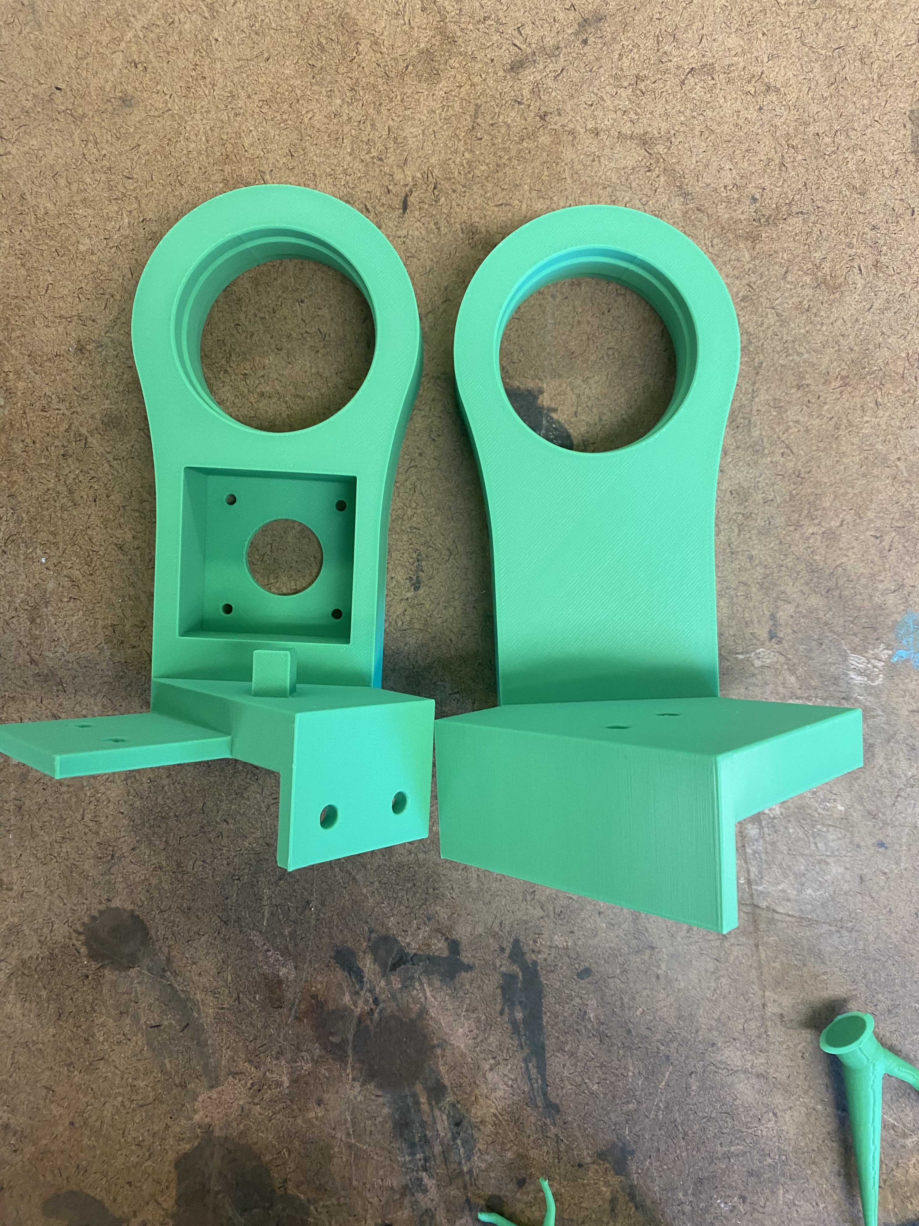
Thankfully Jana had sent 4 others to print and I am printing two more now but it was honestly really exhausting
to see that it did not work. However the motor mounts did end up printing and with the 0.4 nozzle they are CRISP.
We did the second part of the system integration and the motors and pulleys are looking fantastic. The spools printed
great and they were so so clean.
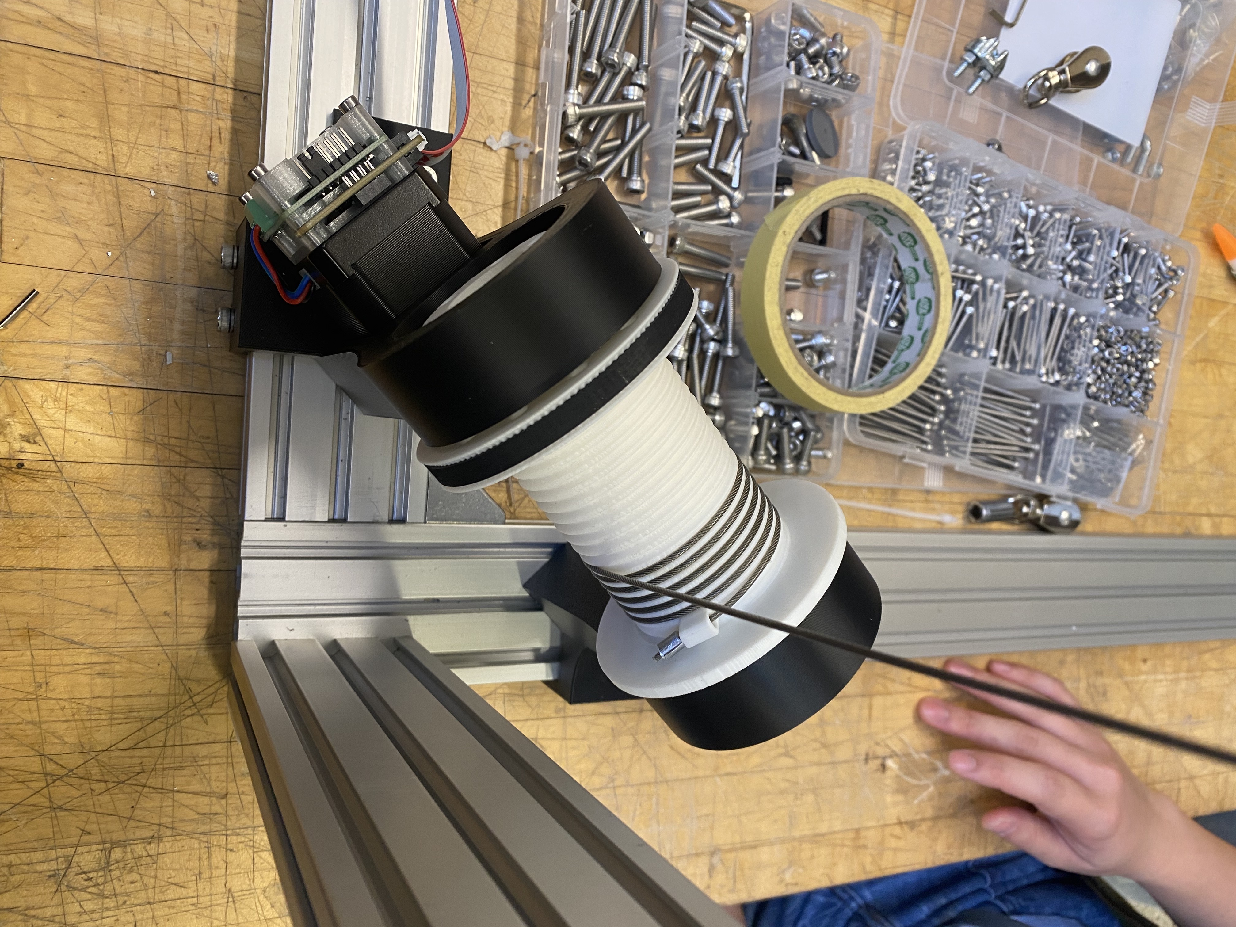
We didn't end up trying the screw integration instead we put metal stoppers that we crimped
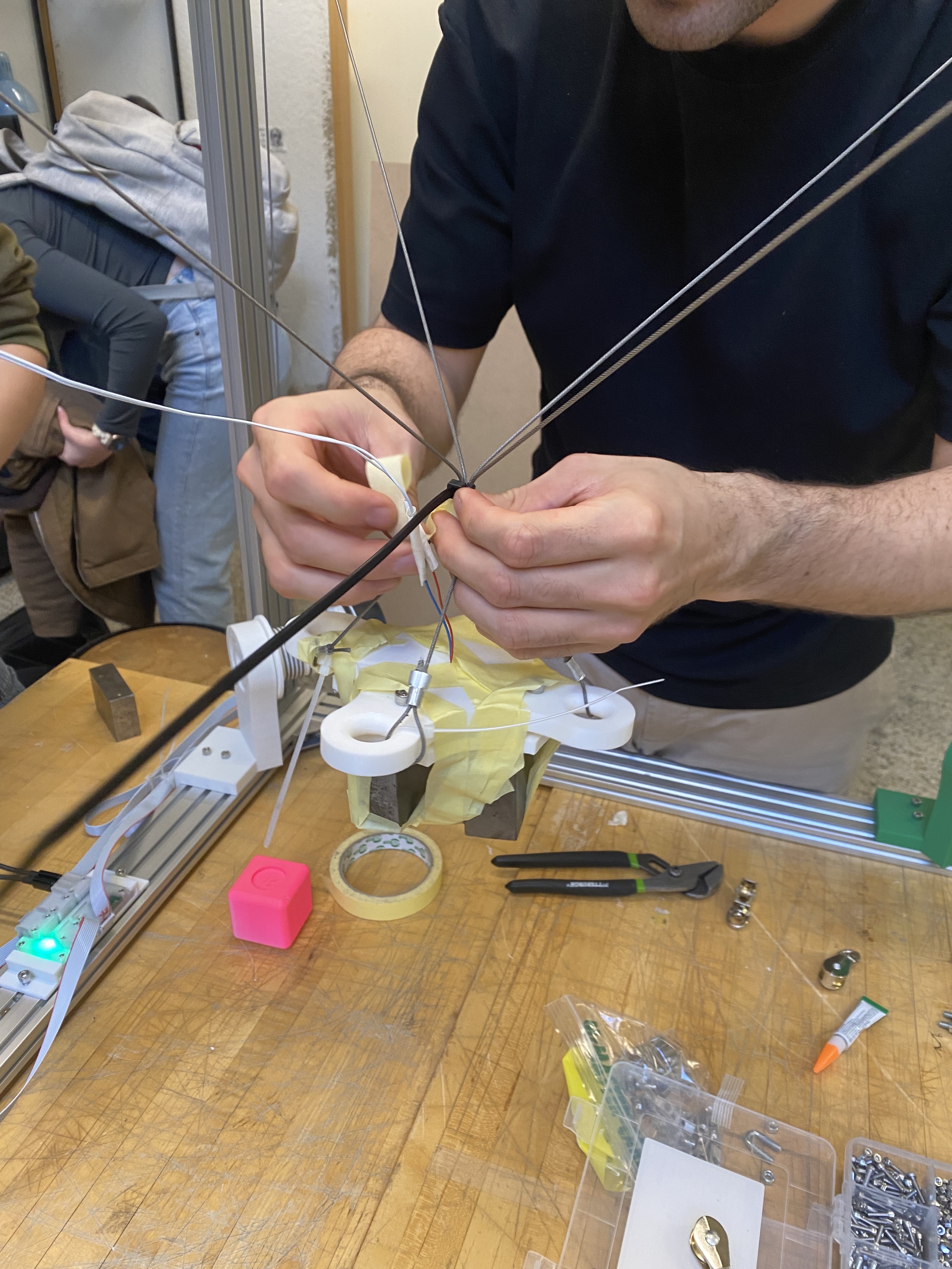
which came out looking really nice. Once we had set up all the motors and we started to attach it to the grabber we realized
that by having only one point of contact for each side the grabber was going to tilt. So we bunched up the cables into
one center point of contact and then added tension to four other points using zipties and then it worked a little better.
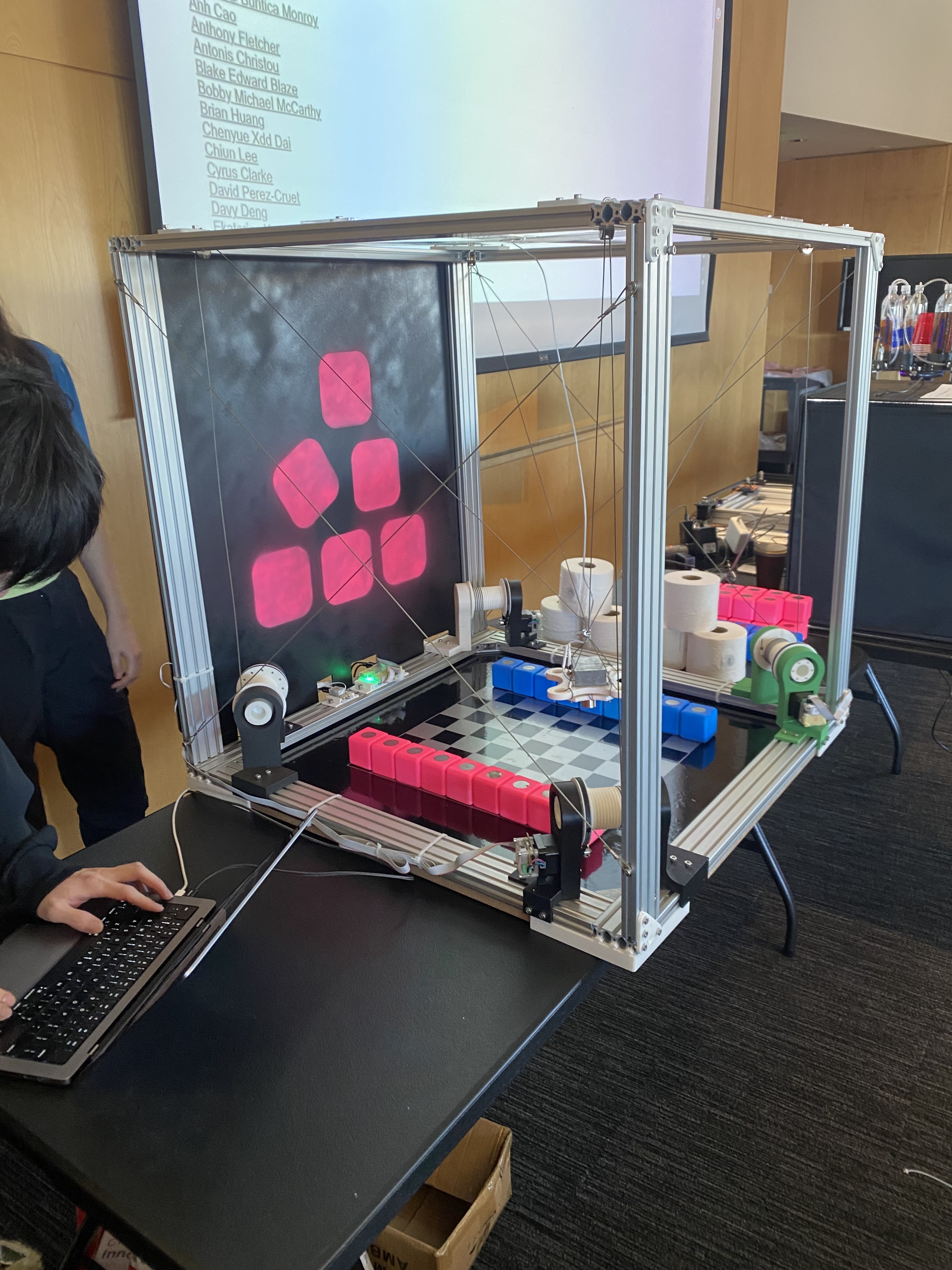
One thing I never really understood is how we can get to the edge of specific locations and when I saw the video
it seems that although we can get to the center we can't get the minimum height in all the box. Hopefully they were
able to resolve that.
