

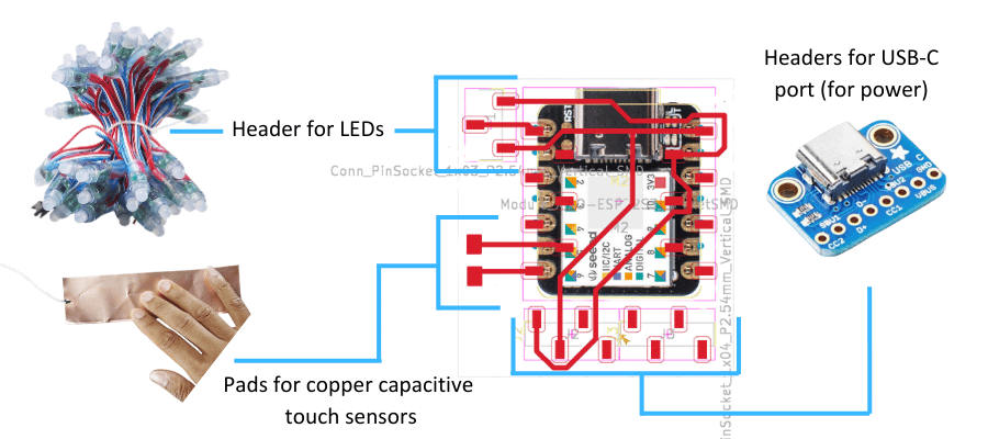
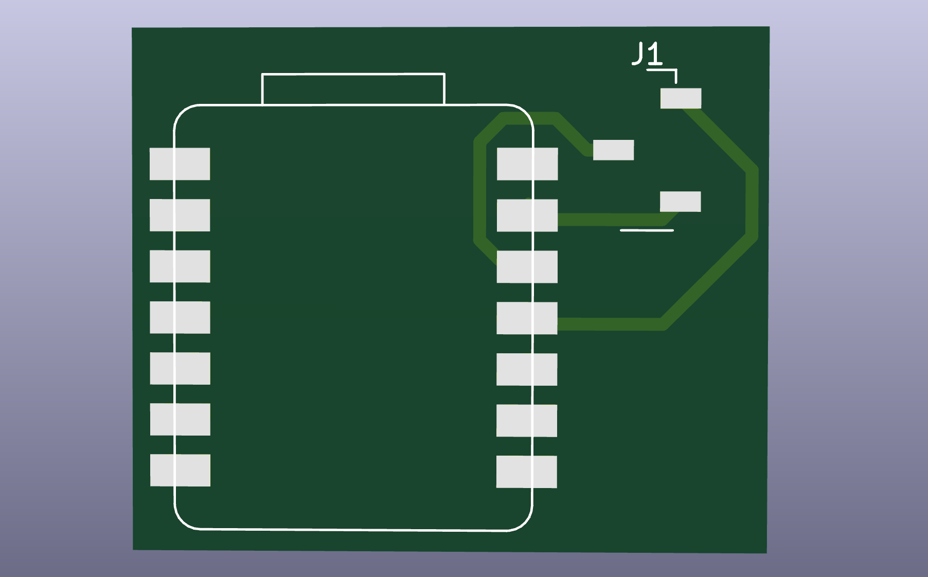
a visualization of my pcb with attached components
for my final project, I need a 5v power supply, a xiao samd21, WS2811 addressable LED string lights, and copper capacitive touch sensors. this is a break down of the electronics:
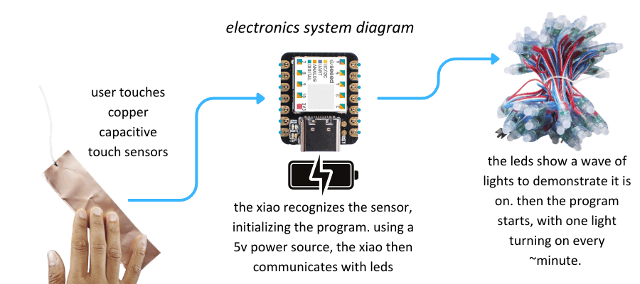
i decided to use the xiao samd21 because leo explained that connecting copper capacitive touch sensors is super easy using this microcontroller board. before building the pcb, i looked at the data sheet of the xiao, my leds, and looked at previous projects using copper capacitive touch sensors. this final project had the clearest explanation for the wiring of parts.
before moving to an EDA, i drew out how i think the parts connected/what i would need my pcb to accomplish.
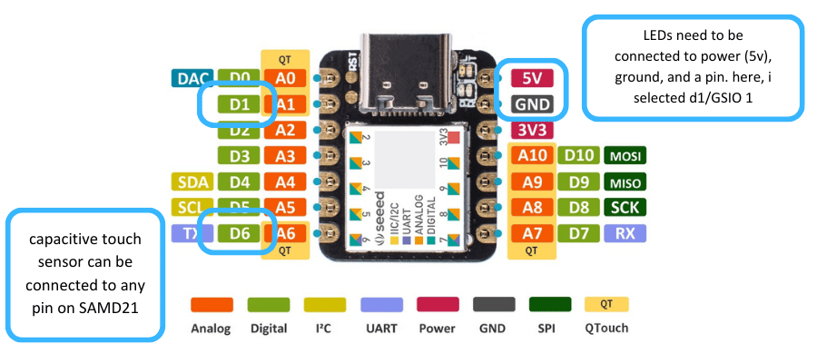
using the understanding above, i looked through the kicad library and selected parts. under leo’s advice, i just used headers for parts for the board. that way, no parts are wasted if the pcb’s routing is off, if i mess up soldering, or if i want a new pcb with different functionality.
for the PCB schematic, i used Module_XIAO-ESP32S3_SocketSMD (a set of headers for the pcb), Conn_PinSocket_1x03_P2.54mm_Vertical_SMD (headers for the LEDs), and two Conn_PinSocket_1x04_P2.54mm_Vertical_SMD (headers for a usb-c connector for a 5v power supply).
i inserted the parts, connected them on the schematic, and assigned footprints to the design in the schematic editor. then i went to the pcb editor. i routed the tracks that were noted in the schematic and added edges to the pcb, and that was it!
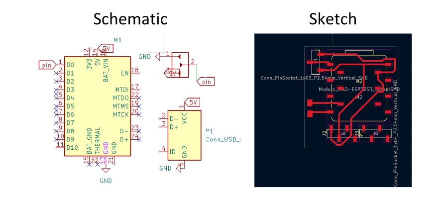
in my first attempt, i just designed a pcb that can connect a xiao and a header for LEDs
to test the operation of a microncontroller circuit board, i used a multimeter and checked the traces of a pcb.
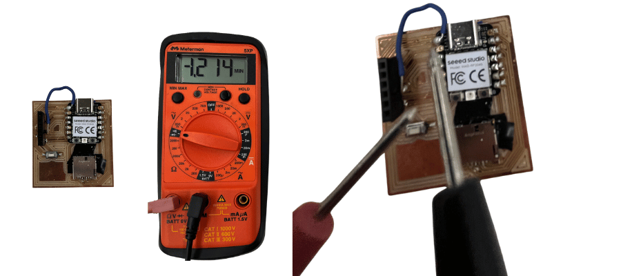
by using a multimeter, which makes a sound when two traces are connected, i could check if a circuit is shorted, and get an understanding of the pcb to see which traces go where. this also lets me confirm that the pins connect to the pins there traces are led to (i.e., if a trace has a break in it that isn't visible, using a multimeter helps us check)
in the case of this pcb, everything is operational!