
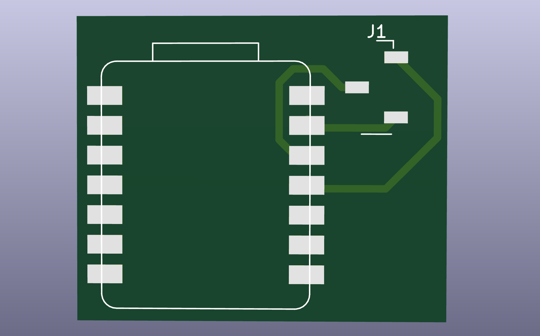
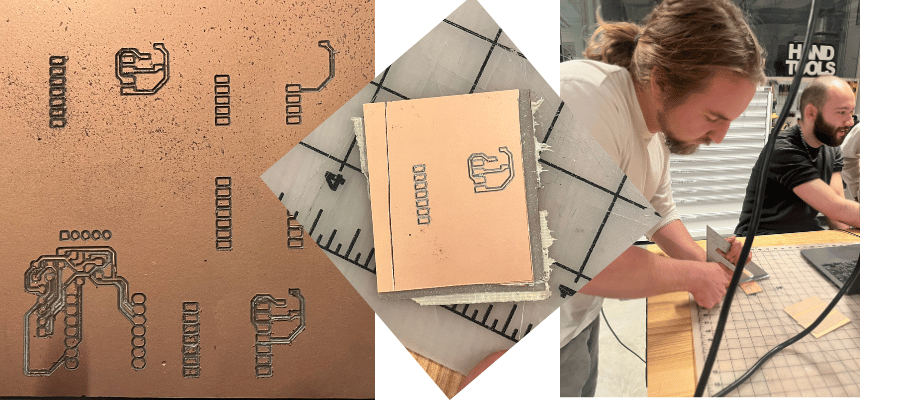
using the original design from last week, i made sure it followed the rules of the cnc by changing the board set up. i used a track width of 16mm, which ended up causing problems down the line. i followed bobby’s instructions (shoutout bobby) to get the cnc up and running (see below).
see below in progress milling photos
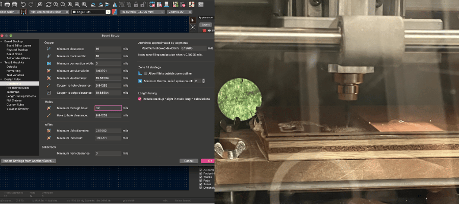
please note that this also fulfills the group assignment, as these are the rules that characterize our in-house PCB production process
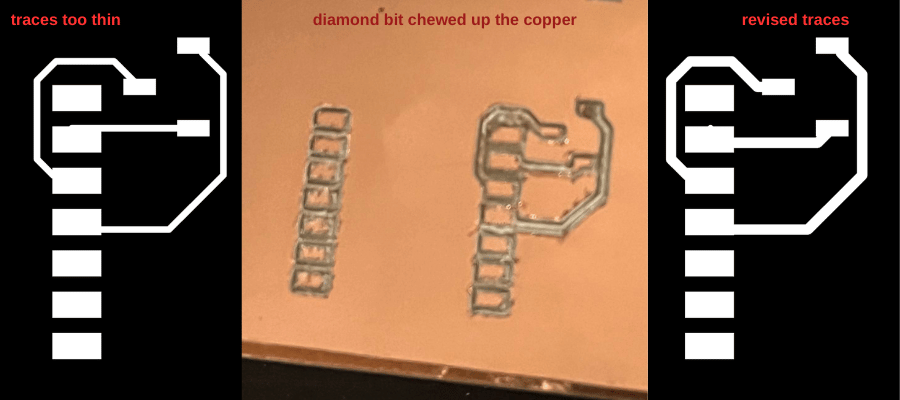
i ran into a problem after milling, which is that i couldn’t get a good cut on the cnc. the machine was sort of chewing up the wires of the pcb. we tried to adjust the depth of the cut and it didn’t realllllllly change the outcome. leo said it was possible the bits were too dull and the bed was not level. my first attempt tore up the traces and i couldn't get a clean cut, so i redesigned the board to thicken the traces
it worked all right (top left corner) except the machine crashed towards the end of the last cut. i felt really sad but then leo told me that it was fine since i wasn’t using the bottom pins anyway. by that time i had removed it from the bed so the only solution was to use a razor and pry the pcb free.
i burned a xiao on the last board, so i decided to retry the pcb with the idea of input week in mind. i wanted to attach an adafruit mems microphone, a xiao, and an LED strip to see if i could control lights with sound.
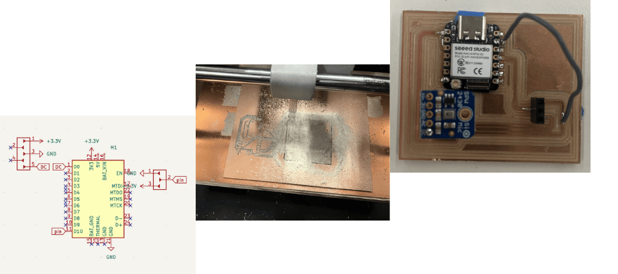
womp womp i broke the pcb while soldering (a trace lifted completely off)
skipping straight pass attempt 3 (which was another failure), leo was kind enough to help me step by step through the process to ensure i got a working pcb
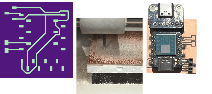
i failed to document the soldering (i was so focused on it that i completely forgot), but thanks to leo's help, it came out great! and fully functional, which was a relief.
first, design in kicad. i recommend using sockets for all elements. that way, if soldering goes awry you don't burn any components.
second, export the gbr files for the front (F.Cu) and edge cuts
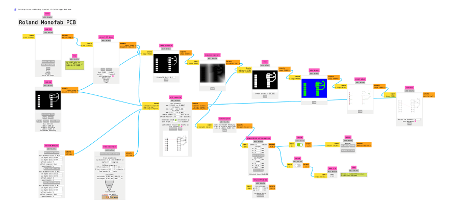
third, drag and drop the gbr files into this website. download the pngs
fourth, prepare the cnc machine by getting a piece of copper plate and taping the back with double sided tape. place firmly on the bed. insert the 1/32 diamond bit into the milling machine.
fifth, go to this website. upload the front traces, and select the first option from the presets.
sixth, follow the on-screen instructions and start the job
seventh, follow steps 5 and 6 for the edge cuts. make sure to change the setting to the third option of the presets.
eigth, remove the pcb from the milling machine and solder on your components.