Golf Ball Dispenser Project
Demo Video:
Project Reflection:
This project proved incredibly rewarding for me. I completed this while fighting off an incredibly strong cold the whole time. I am super grateful to Leo and Joe for helping me out with so many little things. Also, all of my classmates for always giving me good advice and teaching me along the way like David, Alex, Bobby, and Jimi. For my final project, I decided to do something that can help me with my golf skills. I am always annoyed at Topgolf when the balls don't dispense, and you have to wave your club in front to get them to come out. I also like to practice in nearly the same spot on the putting green and wanted something to help keep giving me more balls.
What Does It Do?
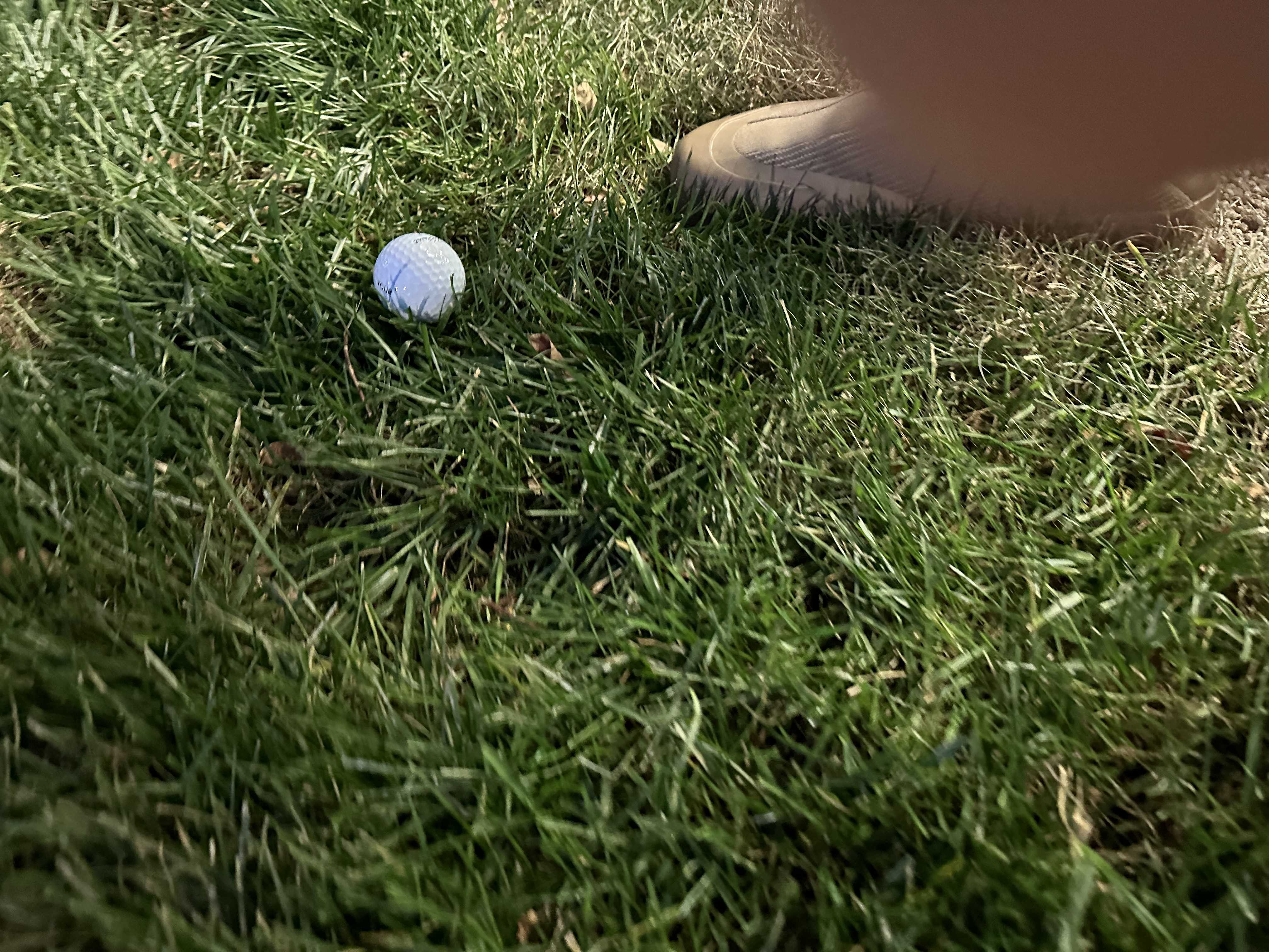
My machine is meant for the golf course and detects whether or not a golf ball is in front of it. If there is one, then it waits for you to put or hit the ball. After you hit it, it dispenses another ball for you. It is great to practice without having to worry about getting up.
Who's Done What Beforehand?
A slight deviation of this exists at Topgolf, but you have to wave your club in front of it a bunch of times after you hit. Nothing like this exists for the putting range, so I am excited to use it.
What Sources Did You Use?
I used help from a lot of my friends and TAs. Edge Impulse to help get the model on the ESP32-CAM. ChatGPT for help understanding concepts. Edge Impulse provided a code library as well to get the initial bounding boxes.
What Did You Design?
- The framing
- PCB board
- Software functionality (the logic of averaging predictions, integrating motor, adding delays for better image capture, integrating system)
- The custom dataset from taking pictures of golf balls on my phone
What Materials and Components Were Used?
- ¼ inch wood
- PCB standard Copper
- Headers
- 4 Electrical wires soldered to ESP32-CAM board
- 3 male-male headers connecting to PCB
- 2 electrical wires soldered to battery holder wires
- 2 male-male headers connecting to PCB
- 2 headers on PCB board
- ESP32-CAM module with ESP32-CAM MB
- SM-S4303R servo motor
- Battery holder
- SuperGlue
- 4 AA 1.5 V batteries
- 3D print resin
Where Did They Come From?
I purchased the ESP32-CAM module. The rest are from the Harvard Lab inventory.
How Much Did They Cost?
- ESP32-CAM: ~$10
- SM-S4303R Servo Motor: ~$15
- Batteries: $4
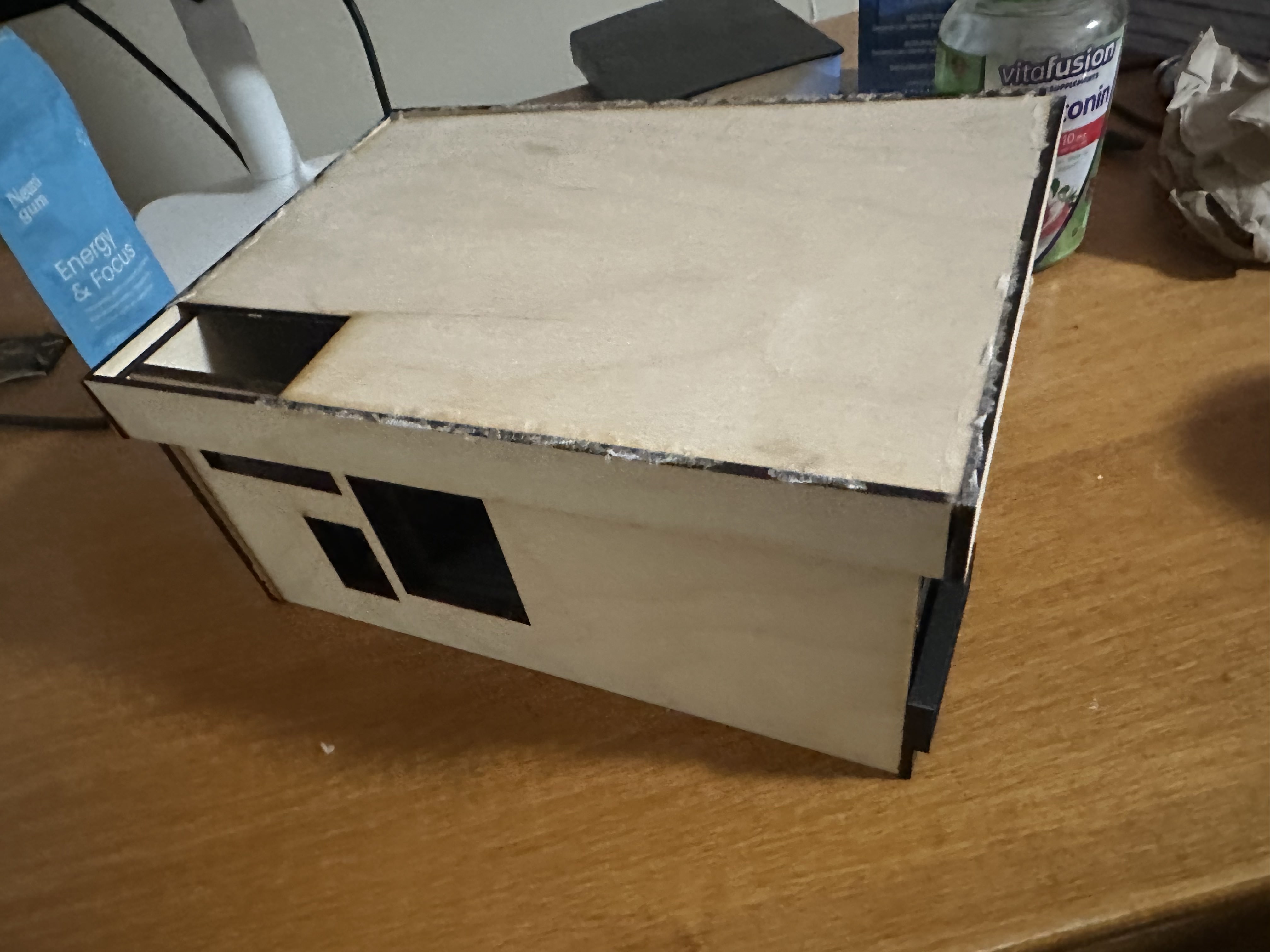
What Parts and Systems Were Made?
- Container frame with lid
- Battery casing
- ESP32-CAM casing
- Servo motor casing
- Servo motor extension to hit ball
- Holding system for golf balls to stay until dispensed
- Software
- PCB board to integrate wires
What Tools and Processes Were Used?
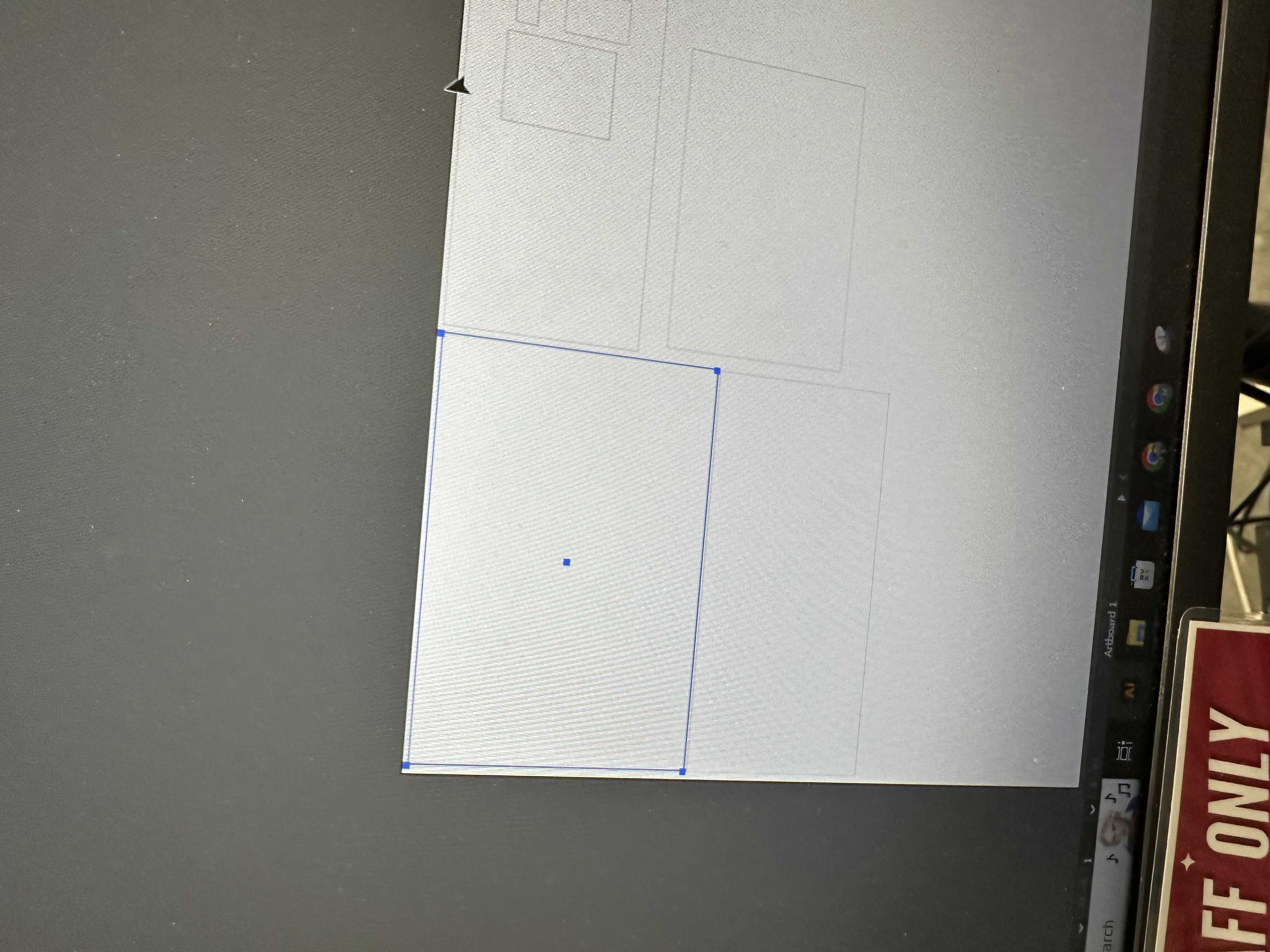
- Fusion/Illustrator for frame design
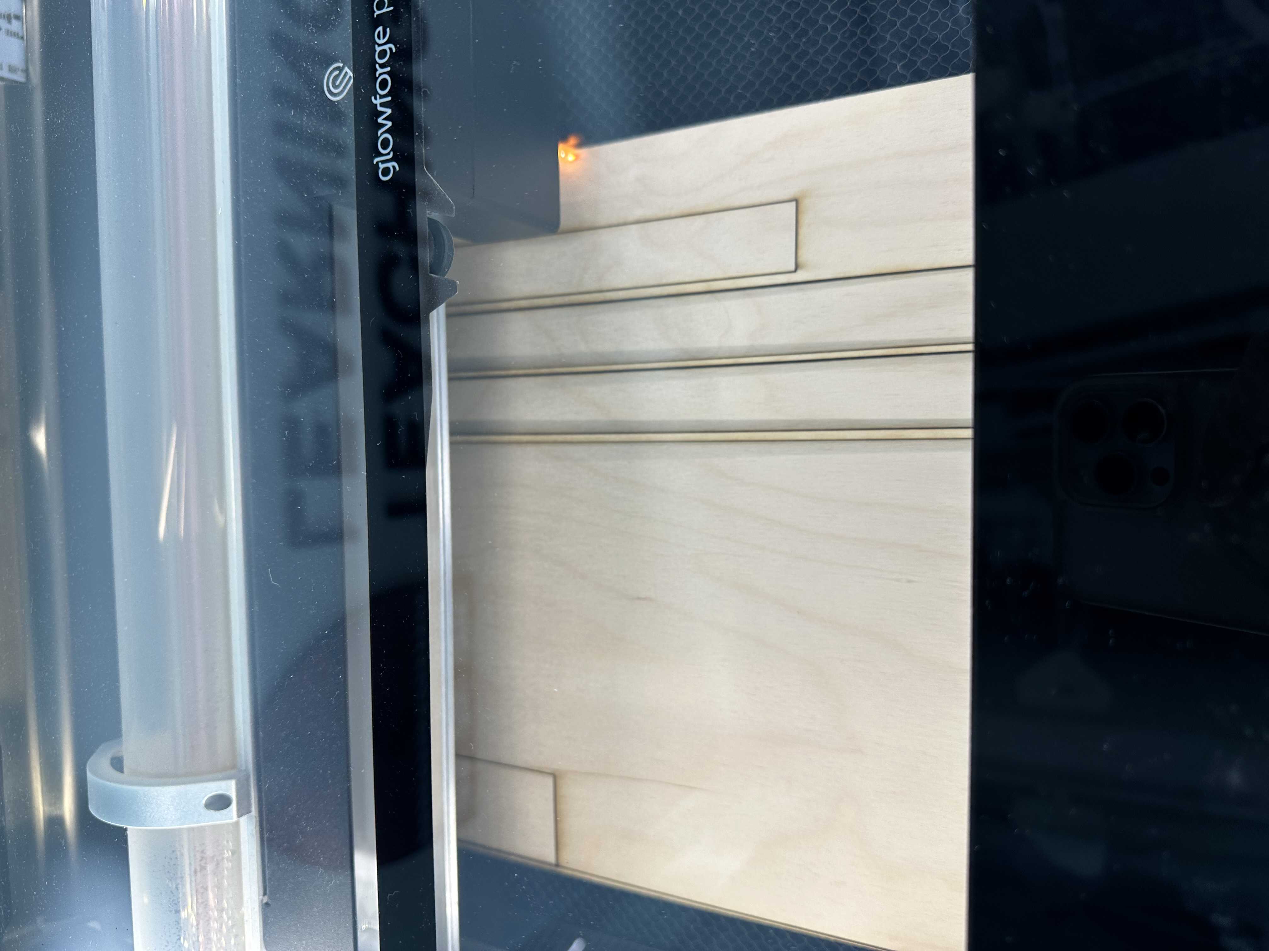
- Laser cutter for cutting wood
- 3D printing for golf ball holder and casings
- Roland SRM20 mill in the REEF for PCB manufacturing
- Traditional soldering techniques
What Questions Were Answered?
Can I finish and can I not quit? I indeed can and did. There were so many moments where I felt lost and did not know what to do, but I kept on pushing and am glad I did. This process was rough, and I learned so many ways things do not work, but at the end of the day, I learned them. I feel like I know I have the skills to truly build almost anything. Not in the sense that I can go finish it tomorrow, but I trust myself to be able to figure it out. This is the literal opposite of me before this class when I did not know a single concept taught in the class. This has been a long journey of self-learning which I have loved. I find myself looking around the built world now and thinking about how stuff works or how I could get that thing to work. This class has also made me much more appreciative of technology and how truly incredible some is.
How well does AI Computer Vision work on microcontrollers? It was alright. It is very constrained by the fact that there is not much memory or computer power. It definitely works best if it is performing object detection on items that have similar backgrounds each inference and look the exact same. I had a bit of trouble with the background, but overall the model performed fine.
What Worked? What Didn't?
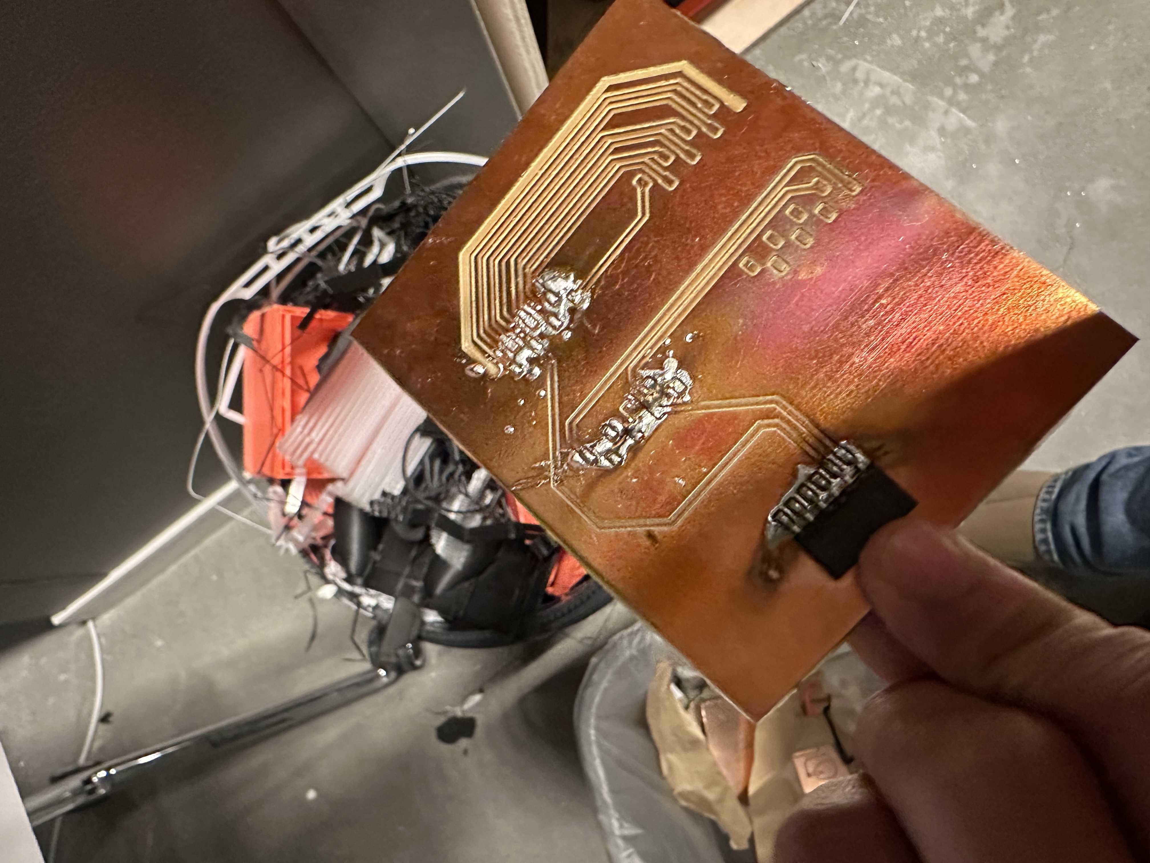
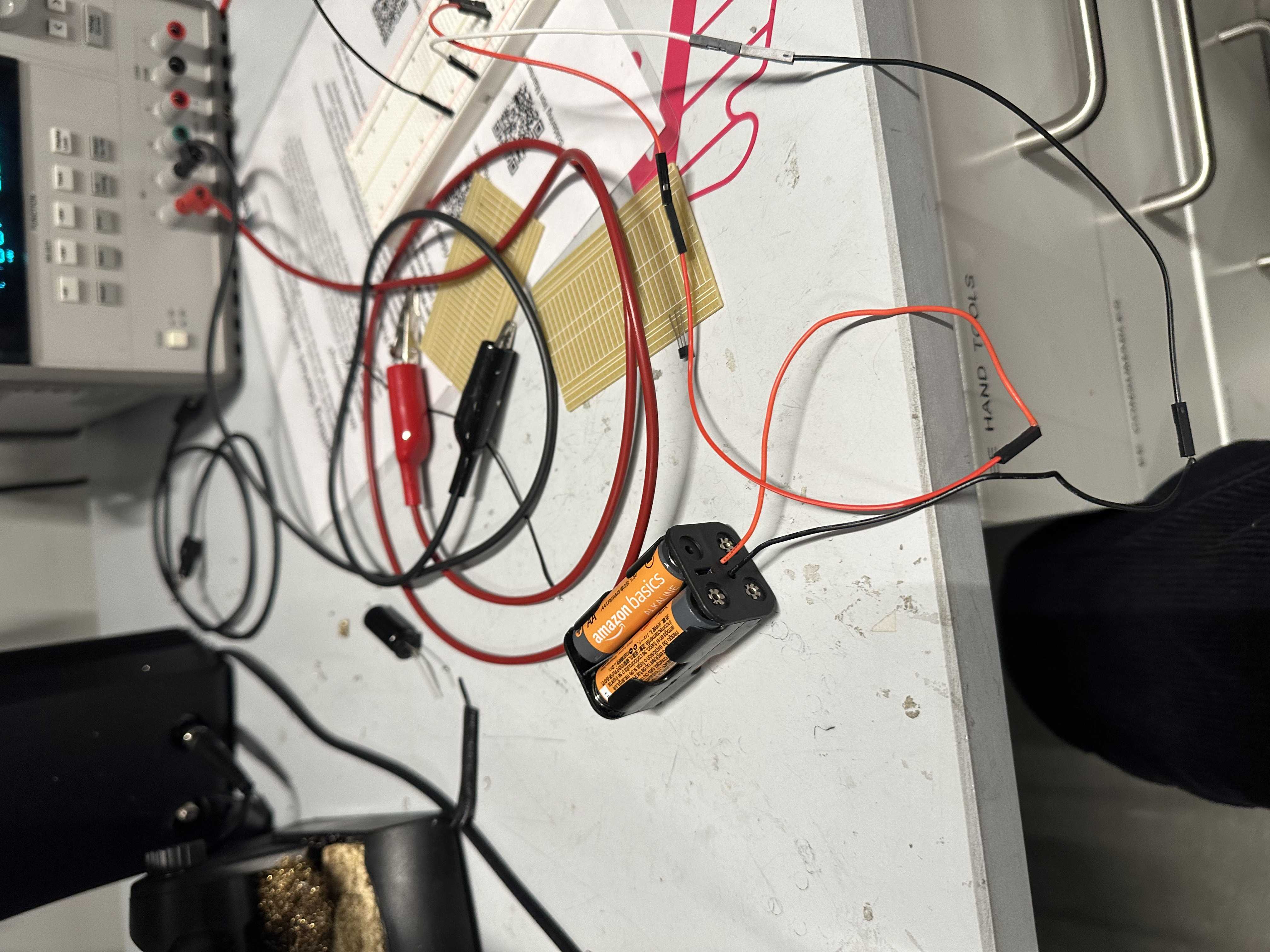
The wiring I did worked as well as the servo strategy to eject the golf ball after it detects that there is no longer a golf ball there. I also would say the embedded AI worked fairly well. The soldering machine at Harvard did not work well, however. I tried both the solder paste/glue that is supposed to be aired with heat, and it would short the circuit. I went through a couple PCBs in this process, and this was perhaps the most frustrating. However, when I soldered in the EE lab, I didn't have this problem. Joe was theorizing that the humidity in the room due to a crack in the window may have something to do with it.
How Was It Evaluated?
Would I be fine with bringing this to a golf course? The answer is yes. The machine works, and it looks good enough to bring with me to practice.
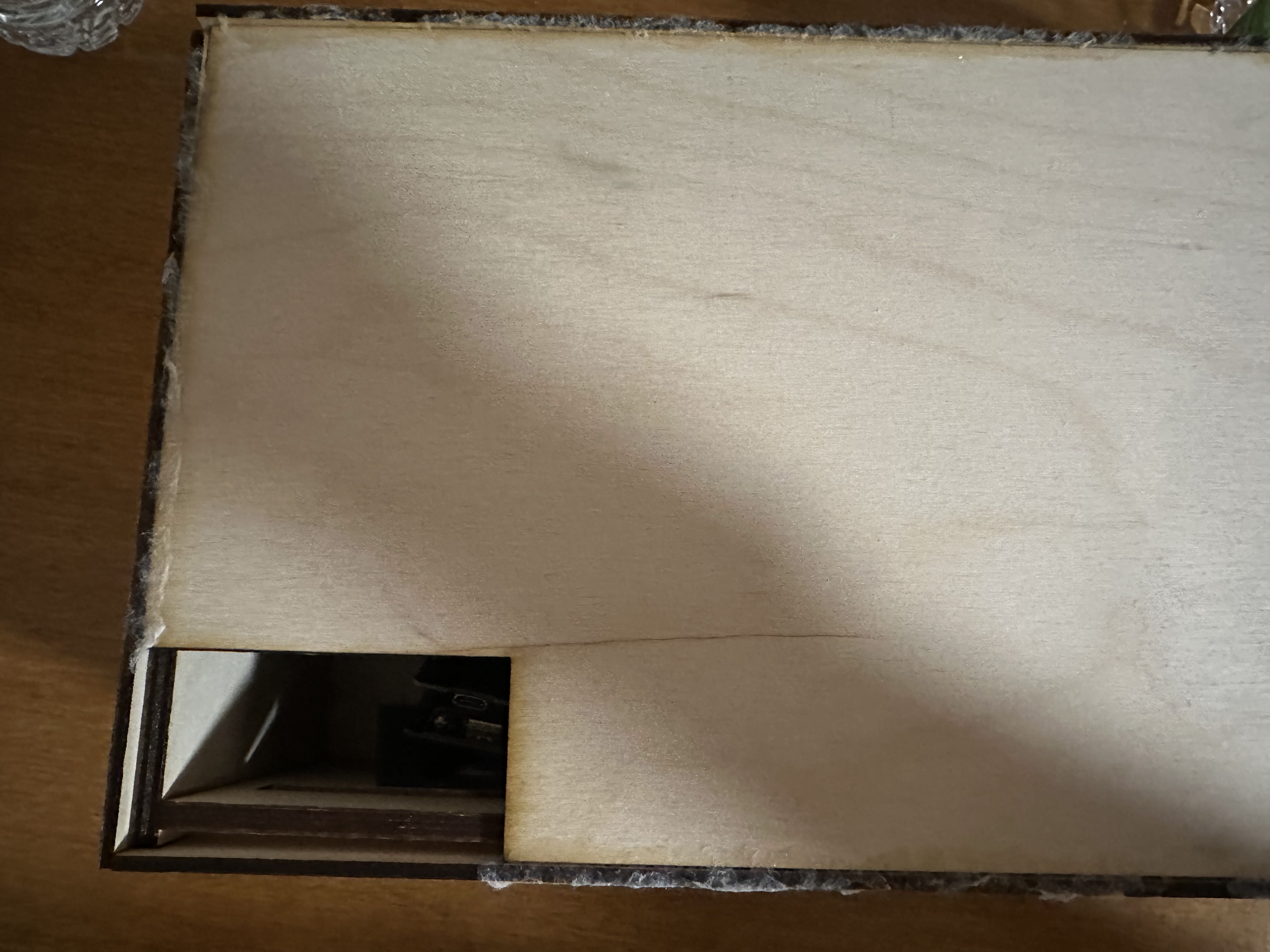
Physical Project
The AI Model:
My first step was recalibrating my algorithm to ensure that it was accurate. I was building upon the model I made for the wildcard week, which already had a baseline level of success in identifying balls. However, since I wanted to dispense a golf ball, I wanted to be sure that the model had a high success rate. I noticed two problems:
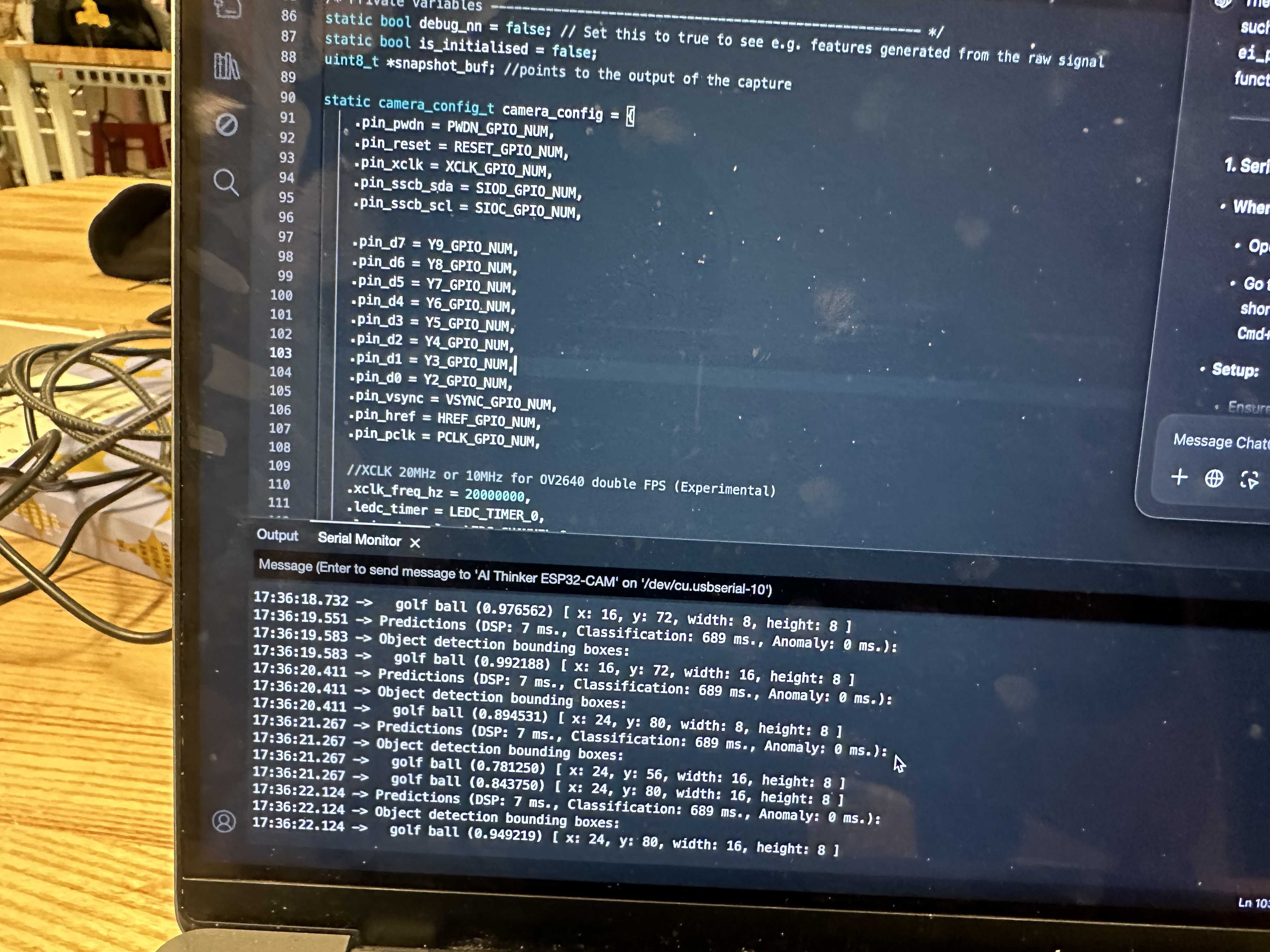
- It would process the same image with different classification scores. To address this problem, I put the model in a for loop to get three predictions on the “same image” and then dispense if the certainty of golf ball is not above 0.6. Each prediction takes about 600ms to complete, so inference is made every 1.8 seconds roughly.
- The background could cause the model to hallucinate. To address this, I created more training data to train the model on. This was done with Edge Impulse, and the images came from me going around and taking photos. I did not anticipate the white background in the final demo day, which caused it to hallucinate slightly, but overall, the model was pretty robust with the scorings below.
The exact model can be accessed here or, if this link corrupts in the future, at Edge Impulse project number 583266.
I then downloaded the model to my ESP32-CAM and started testing the inference ability, which was pretty robust.
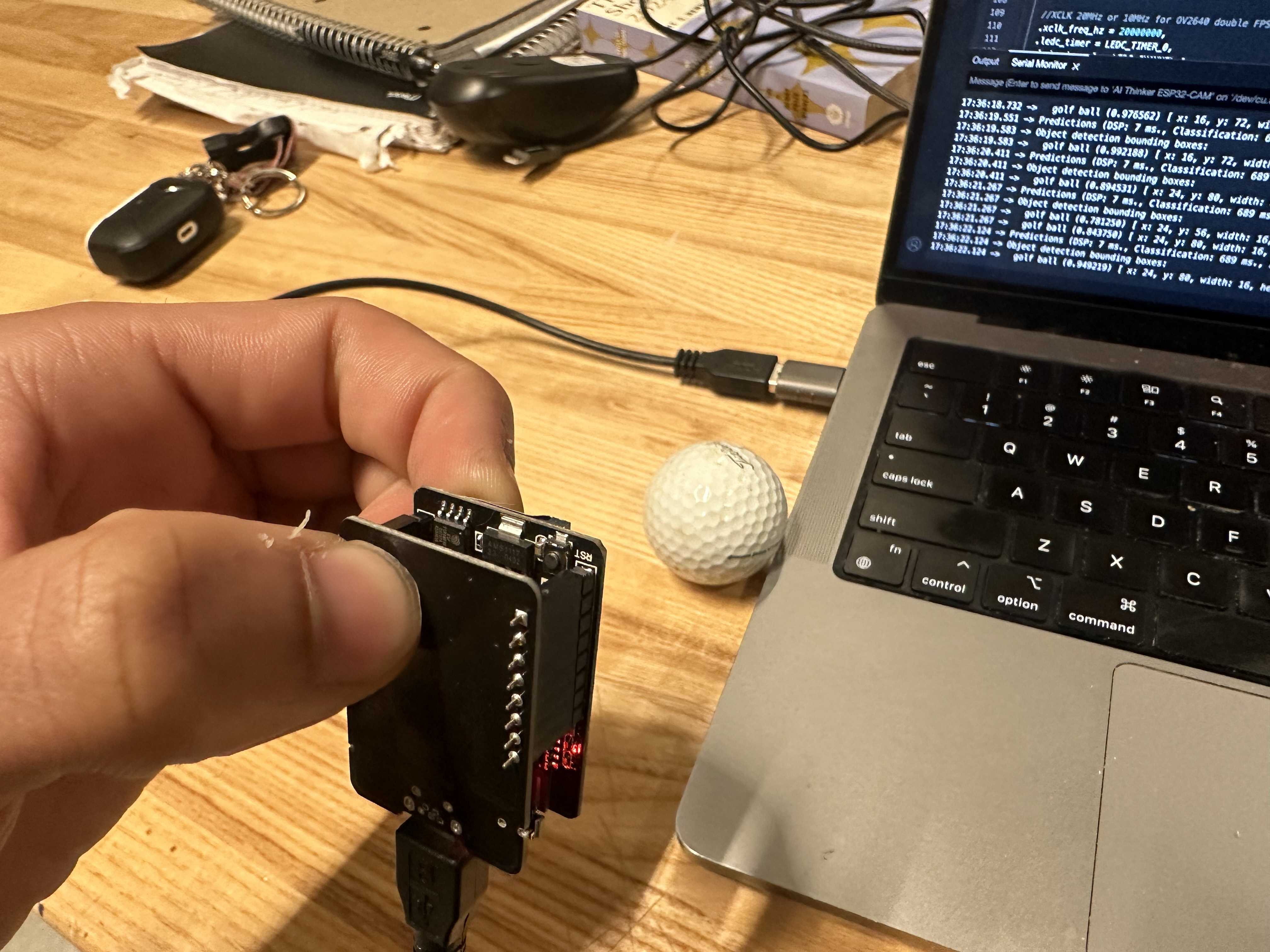

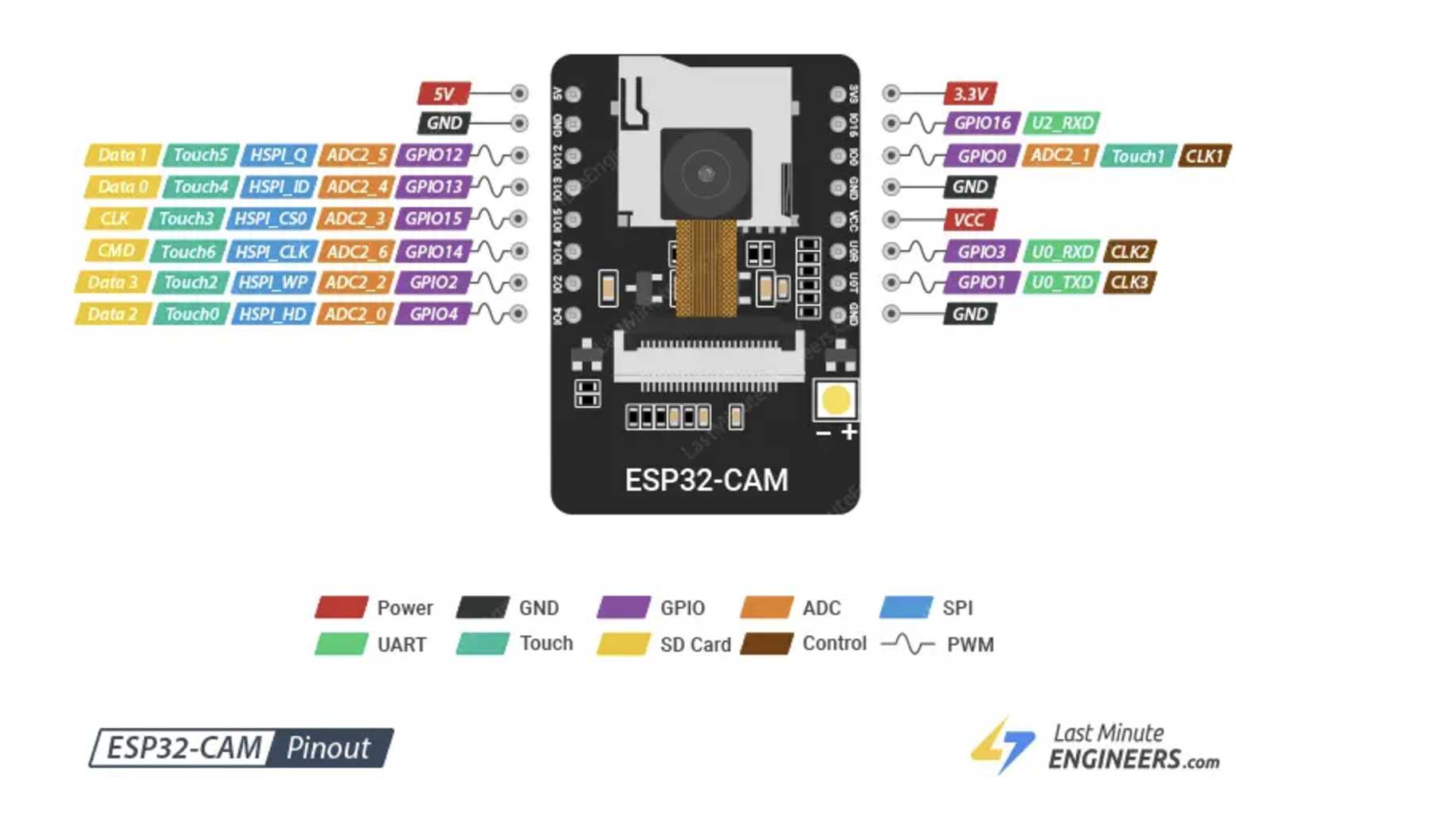
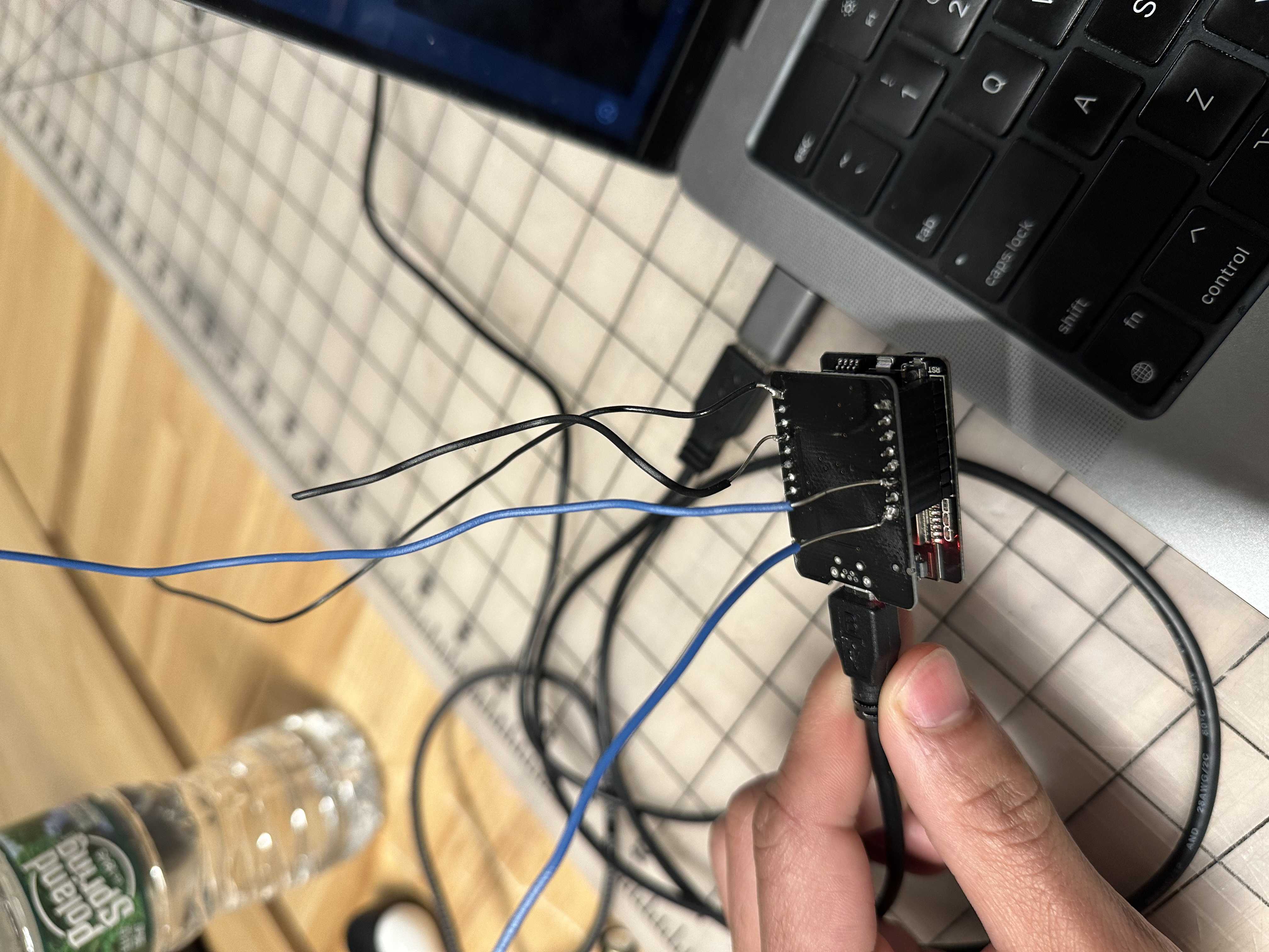
Connecting the ESP32-CAM:
The next step in my development was finding a way to attach the ESP32-CAM to other components. Because the set I had was already connected together on the front and back with the ESP32-CAM MB, it did not provide an easy way to solder onto a PCB. I did not want to mess this up since it was the only one I had. I originally tried to mill a PCB board, but because the fab lab did not have 8-head SMD components or the ESP32-CAM footprint, this proved difficult. I downloaded the footprint online, but this was not SMD, and it would have been extremely difficult to do a good solder job given that the piece would have to be vertical and the ESP32-CAM MB did not provide inserts that could be stuck into other things.
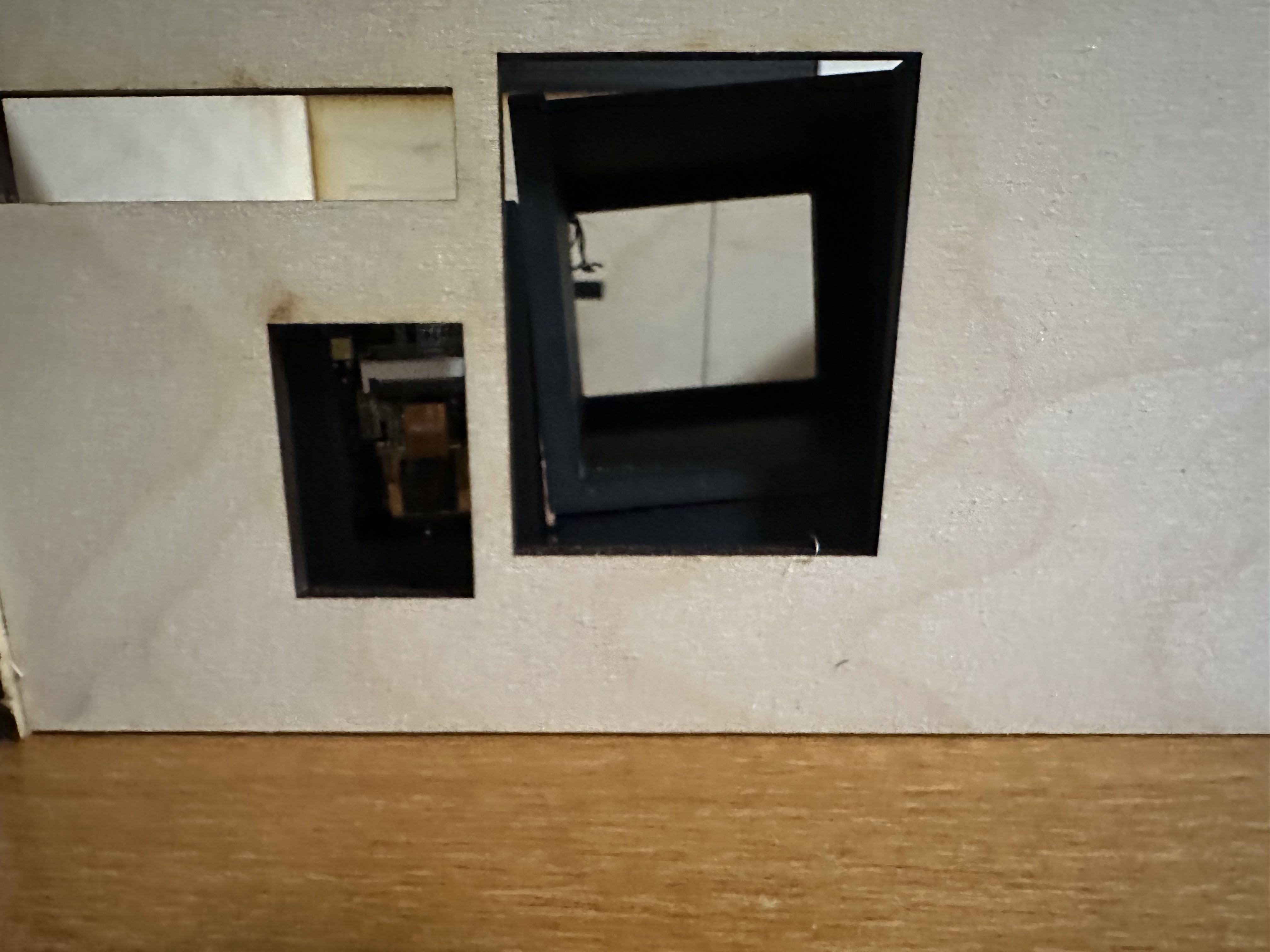
After 3 hours of trying this, I know that it is a bit nasty, but I soldered wires onto the little stubs to make the connection. Because of my functionality needs, I only required 3 (I have 4 wires because the first GPIO pin I was trying to use would not work with a servo even though it has PWM capabilities. I was also crunched for time, so I decided to just go with the other one). I made a container for the camera and attached it to the wall I describe later with a viewing area for the camera.
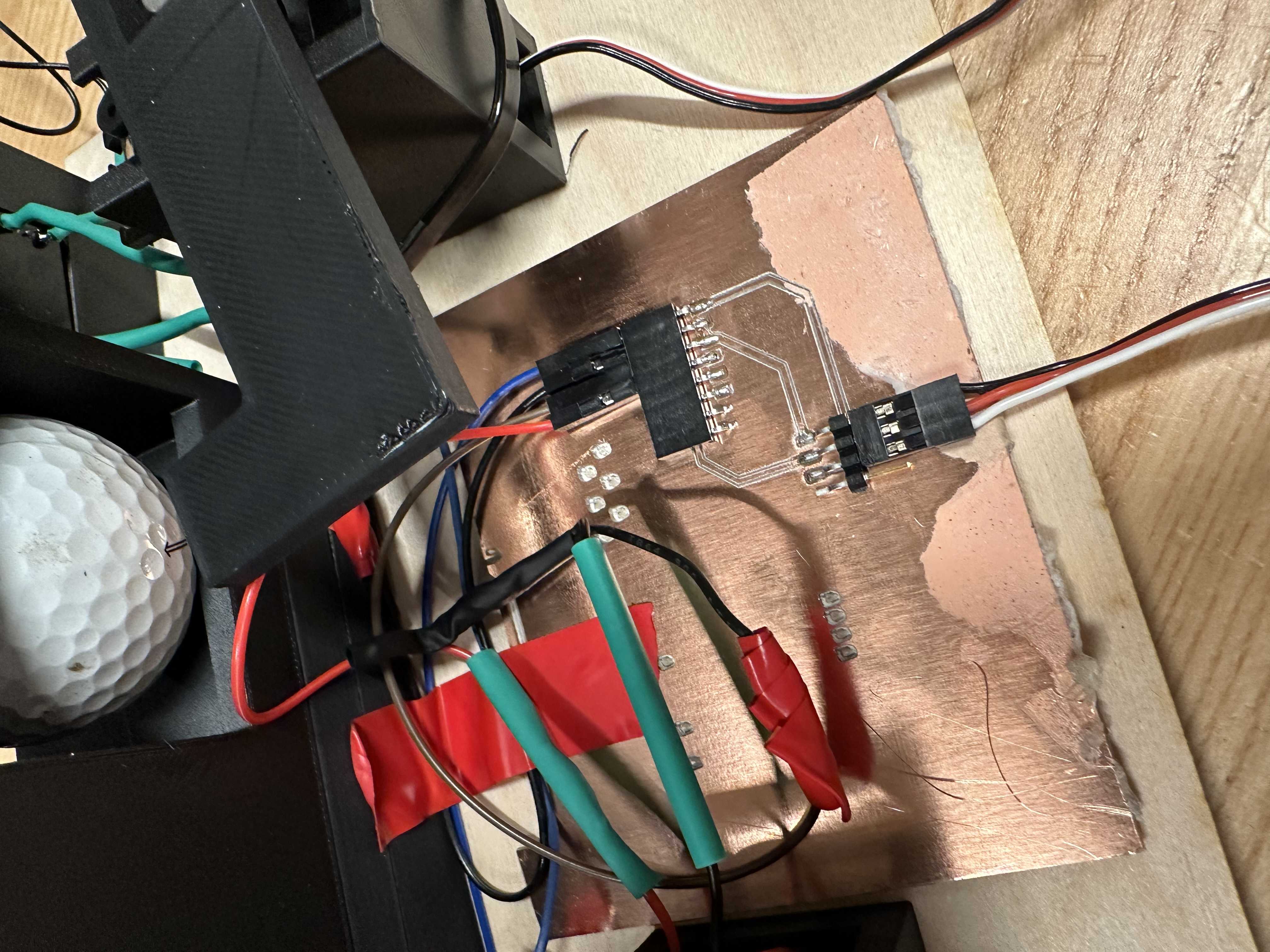
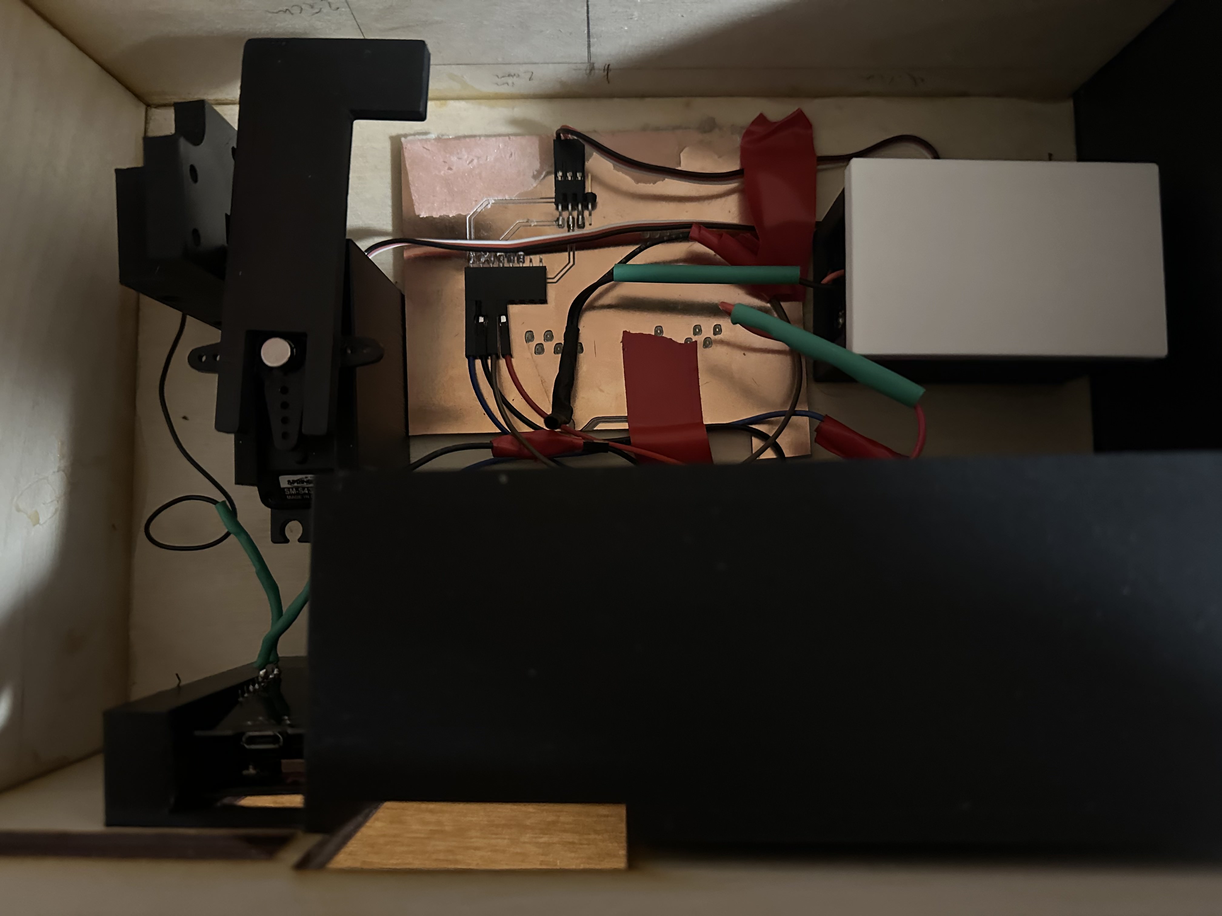
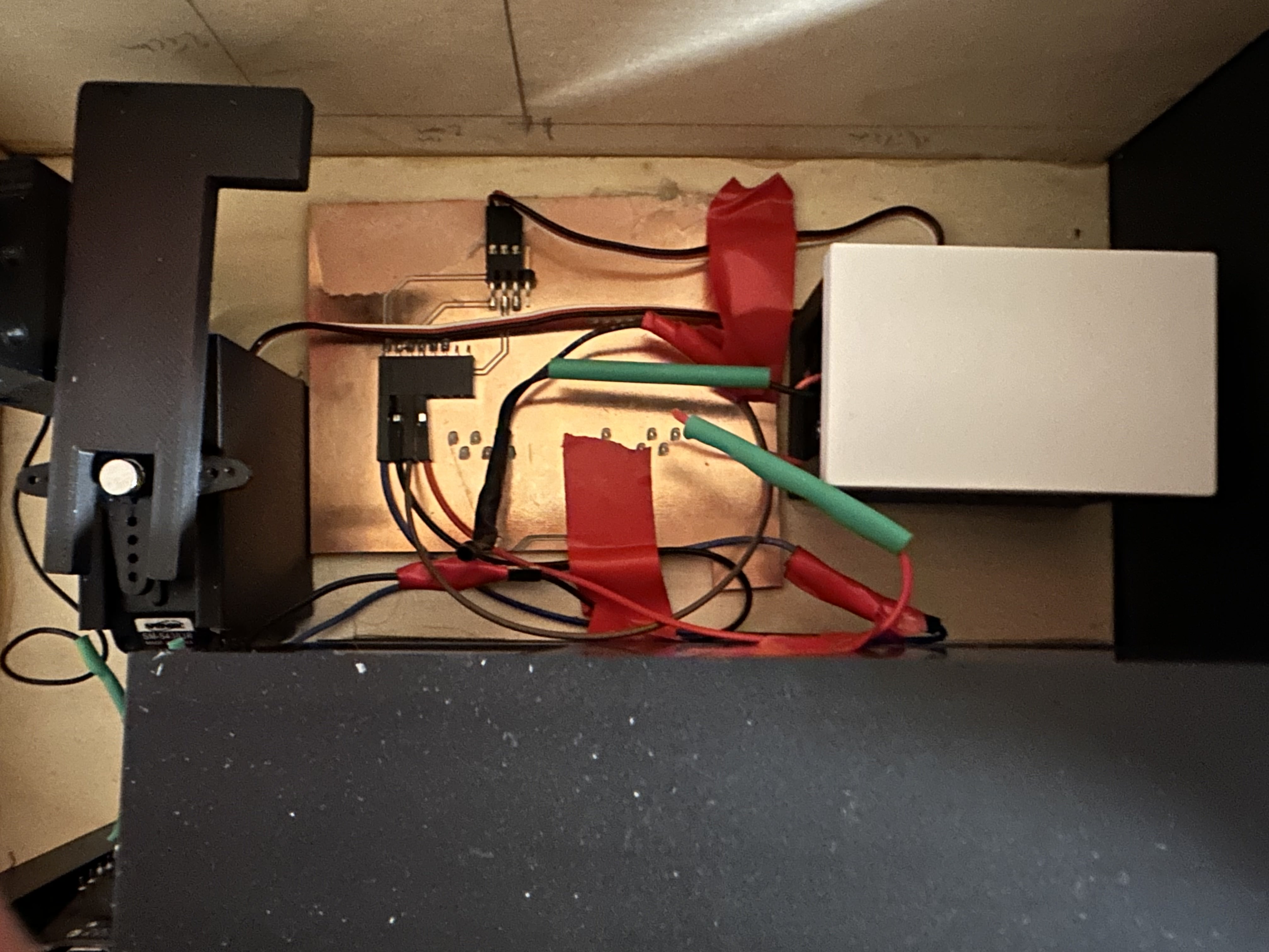
Servo Motor and Battery:
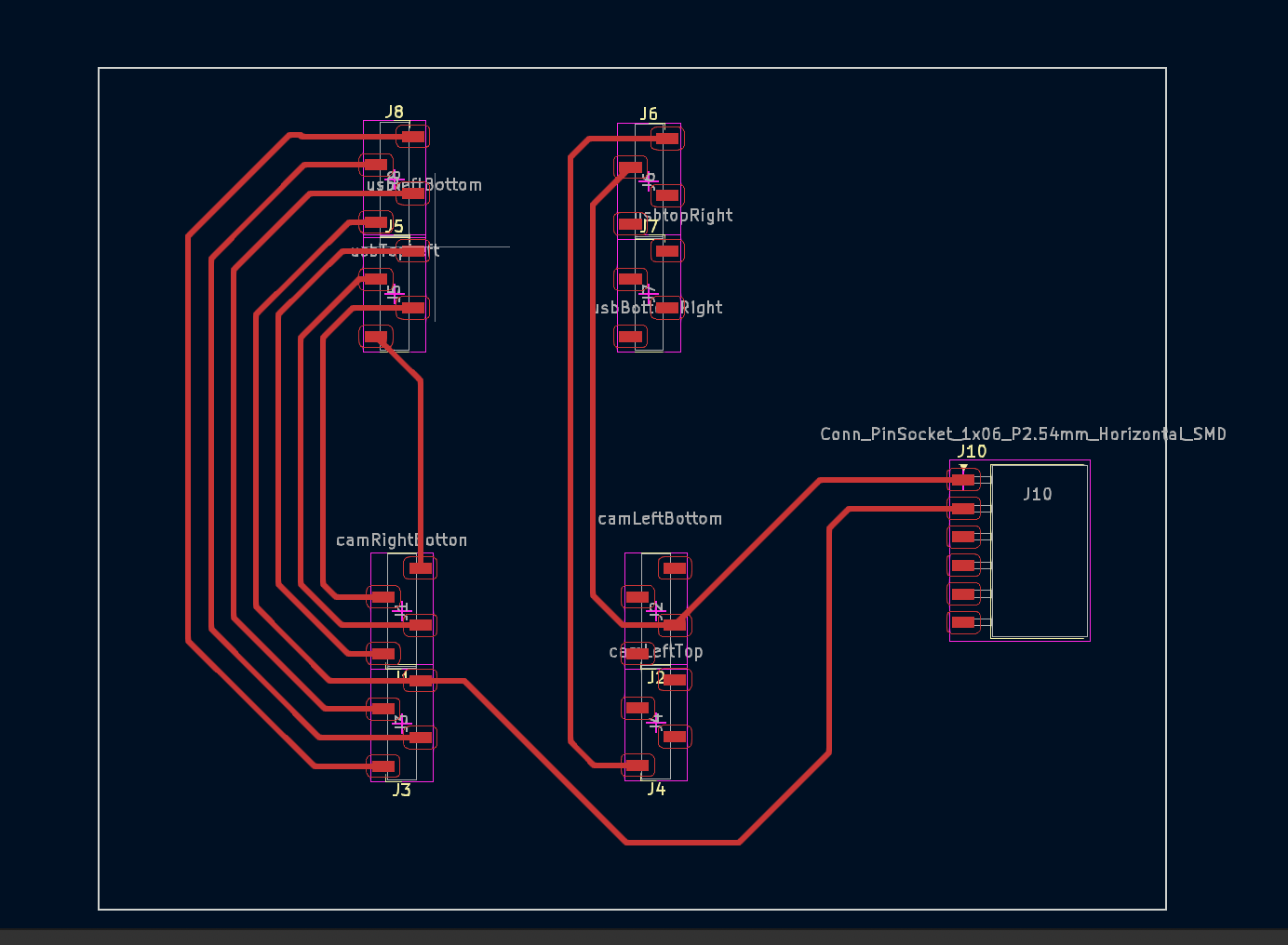
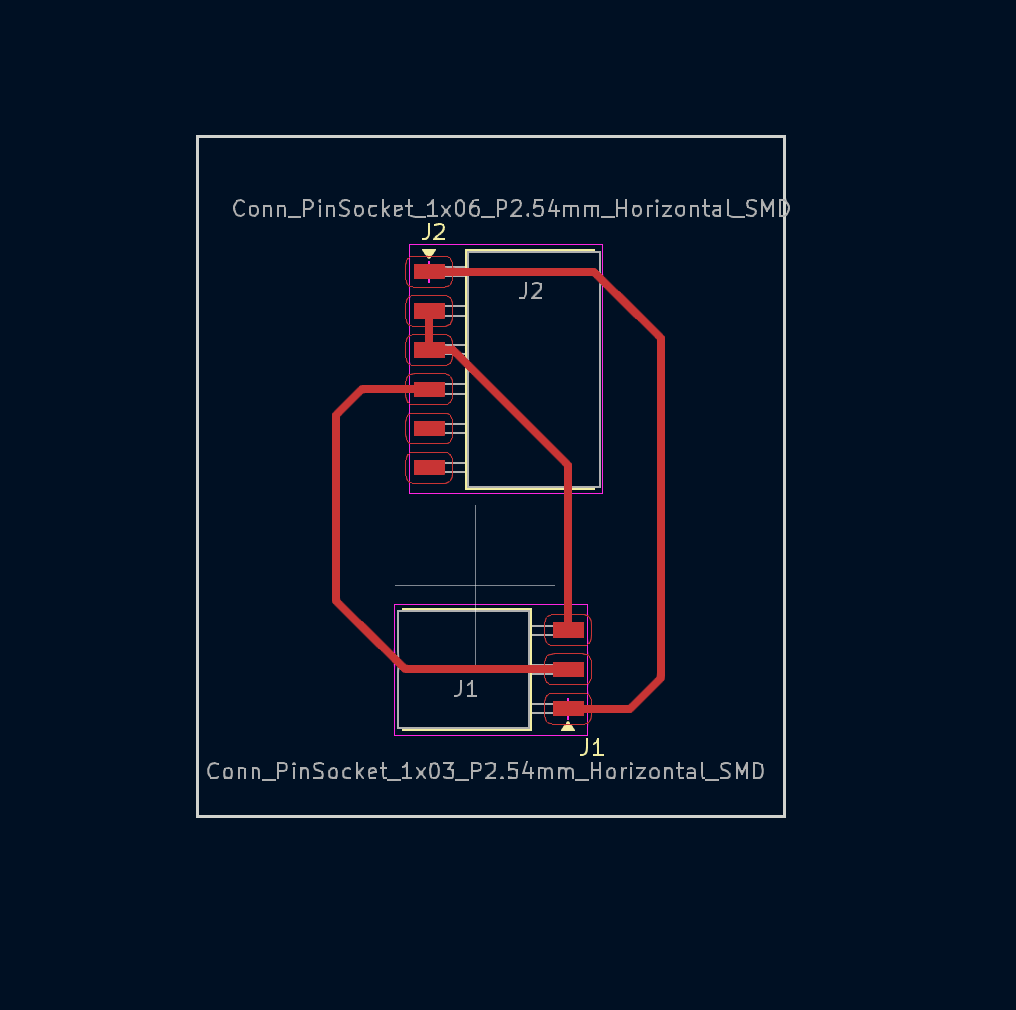
I have had experience with servo motors before during output week, and my final project built upon this. This portion was pretty straightforward connection-wise. I printed a PCB to join the servo and the battery with headers to plug the wires of the battery into and pins sticking out to plug the servo into. I also put the wires from the ESP32-CAM into this PCB board on the same side as the battery. The connections are as follows:
- Positive of battery to positive of servo
- Ground of all three together
- GPIO pin 14 to the switch of the servo
I ended up having to tape these wires down on the PCB to not get in the way of the servo’s rotation.
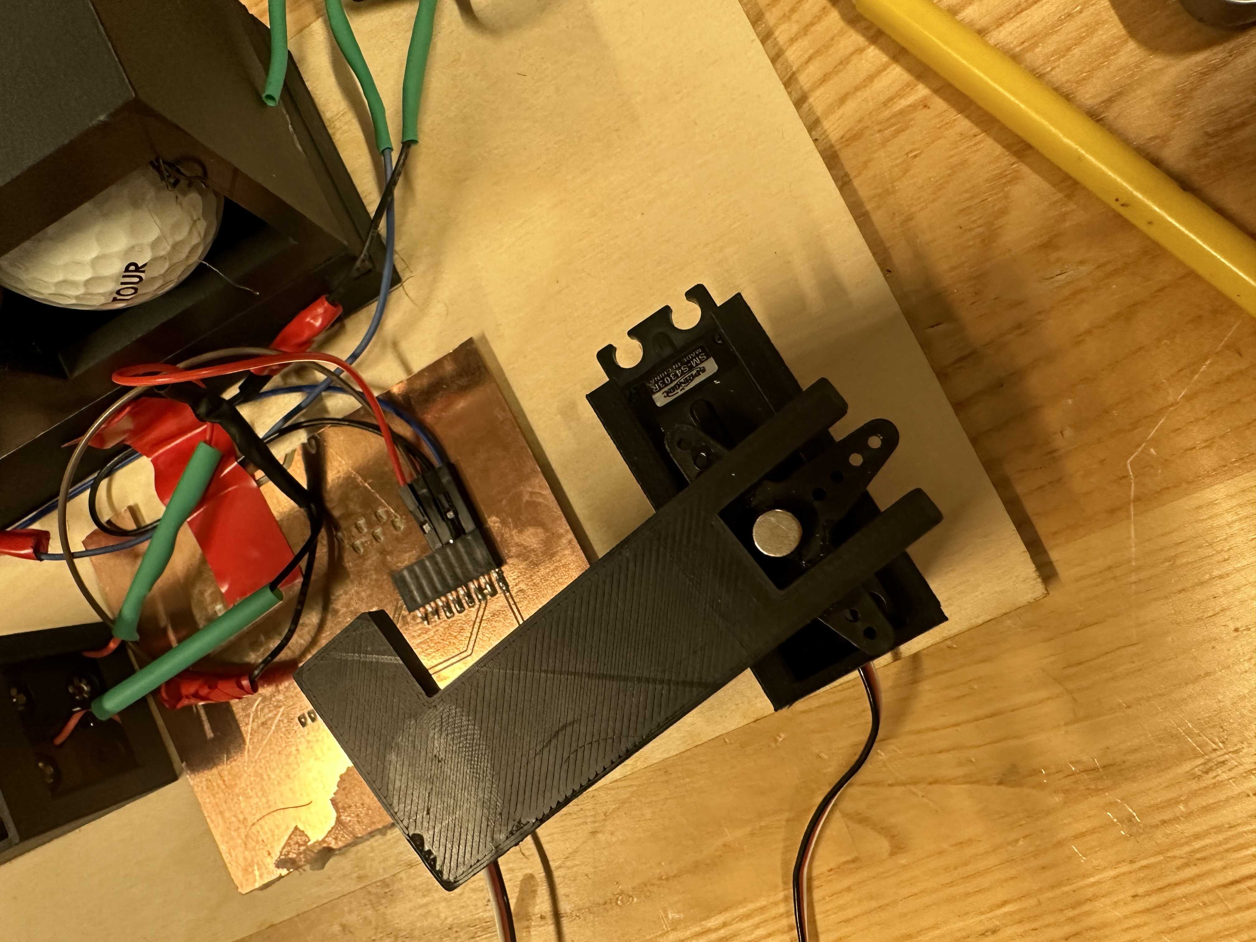
I additionally attached a 3D-printed piece to the top of the servo motor with glue in order to hit the ball out of the container.
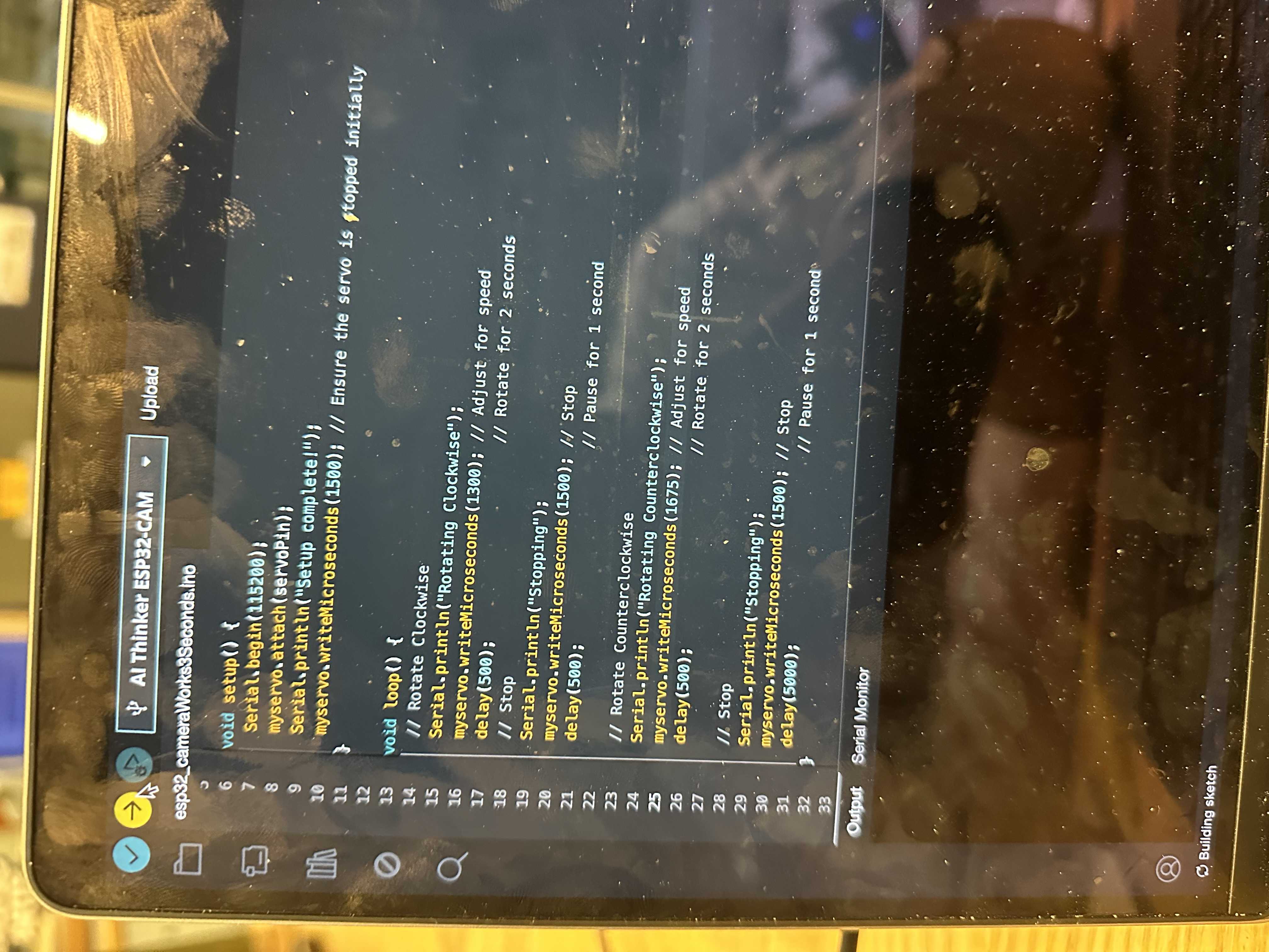
I used an SM-S4303R continuous rotation servo motor. This is a continuous servo motor rather than one that takes position. This proved to be a bit of a pain initially because I needed to ensure that the motor returned to the same position. The motor works by setting a pulse programmatically above or below a threshold (in this motor's case, that threshold is 1500). You then set the time you want the motor moving at this pulse. I played around with the speed of increasing and decreasing the magnitude of deviation of the threshold. I ended up doing clockwise at 1300 for 590ms and 1700 (counterclockwise) at 590ms. I noticed that this motor would always end up a little more counterclockwise than when it started, so I added a stopper behind the motor so it would not go past that point on its way back. This made it so that the motor would move up 180 degrees to hit the ball and then back 180 degrees to the return position. I engaged the battery with a 3D print and a lid and slid the servo motor into a 3D-printed cage. I use 4 AA 1.5 V batteries.
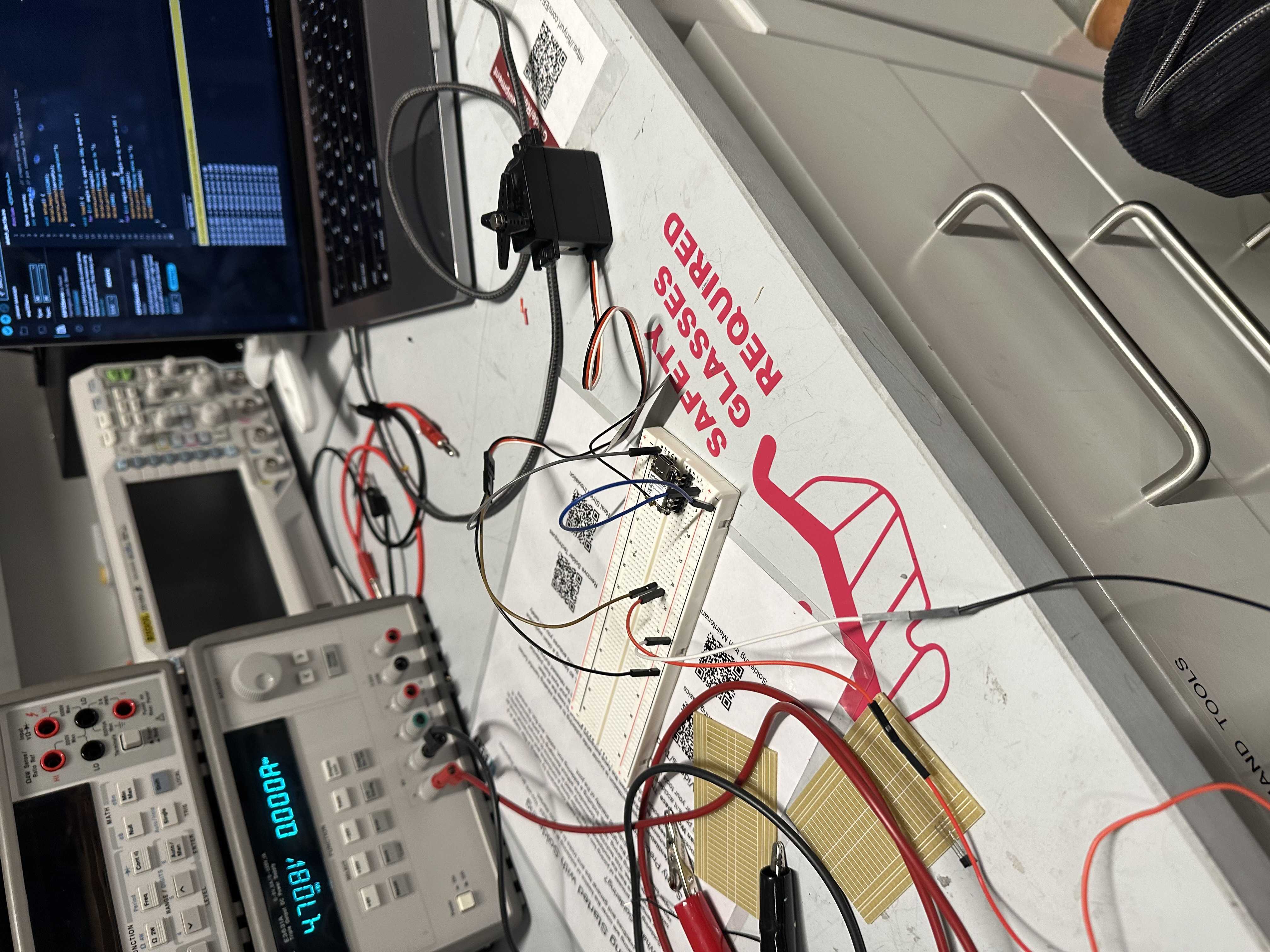
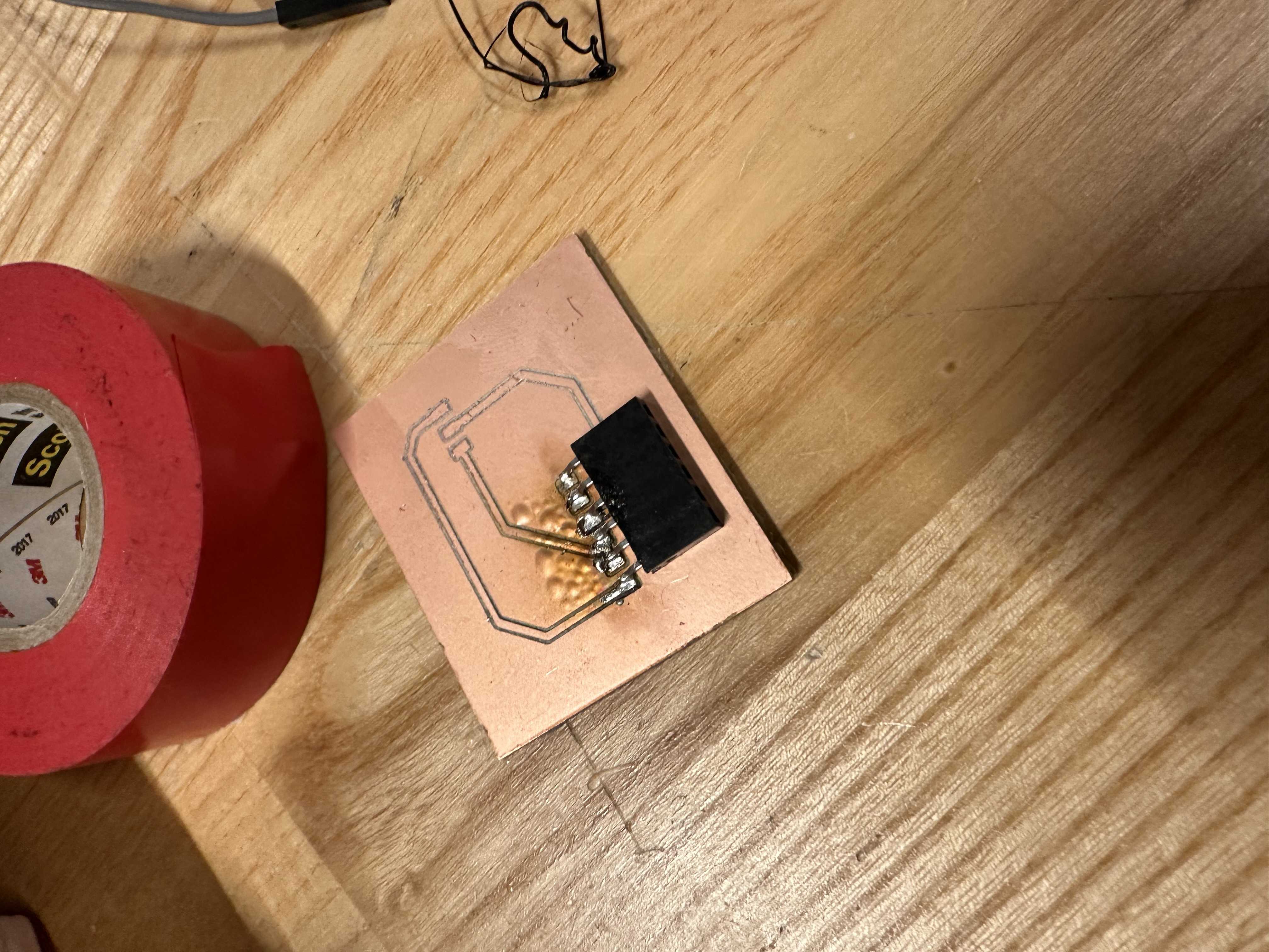
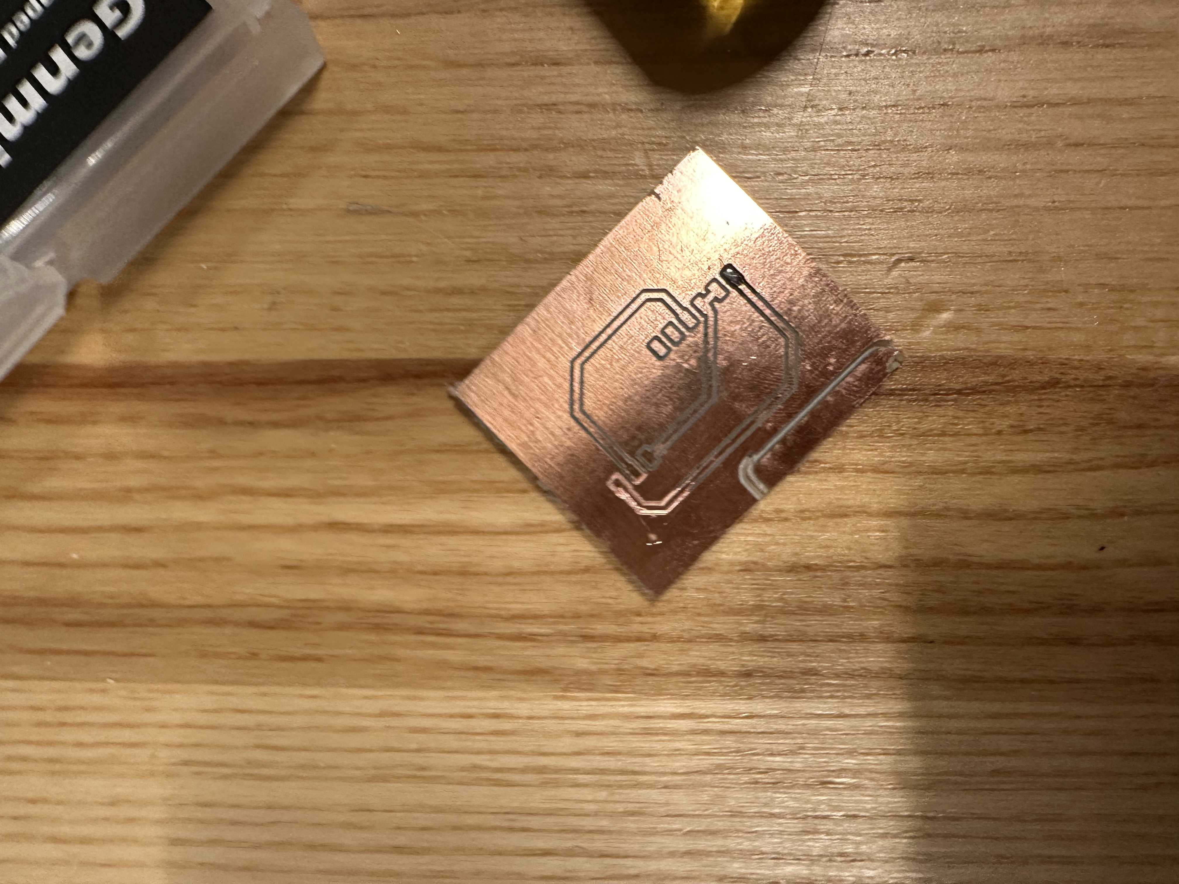
I end up using this PCB design to connect my Servo, battery pack, and esp32cam
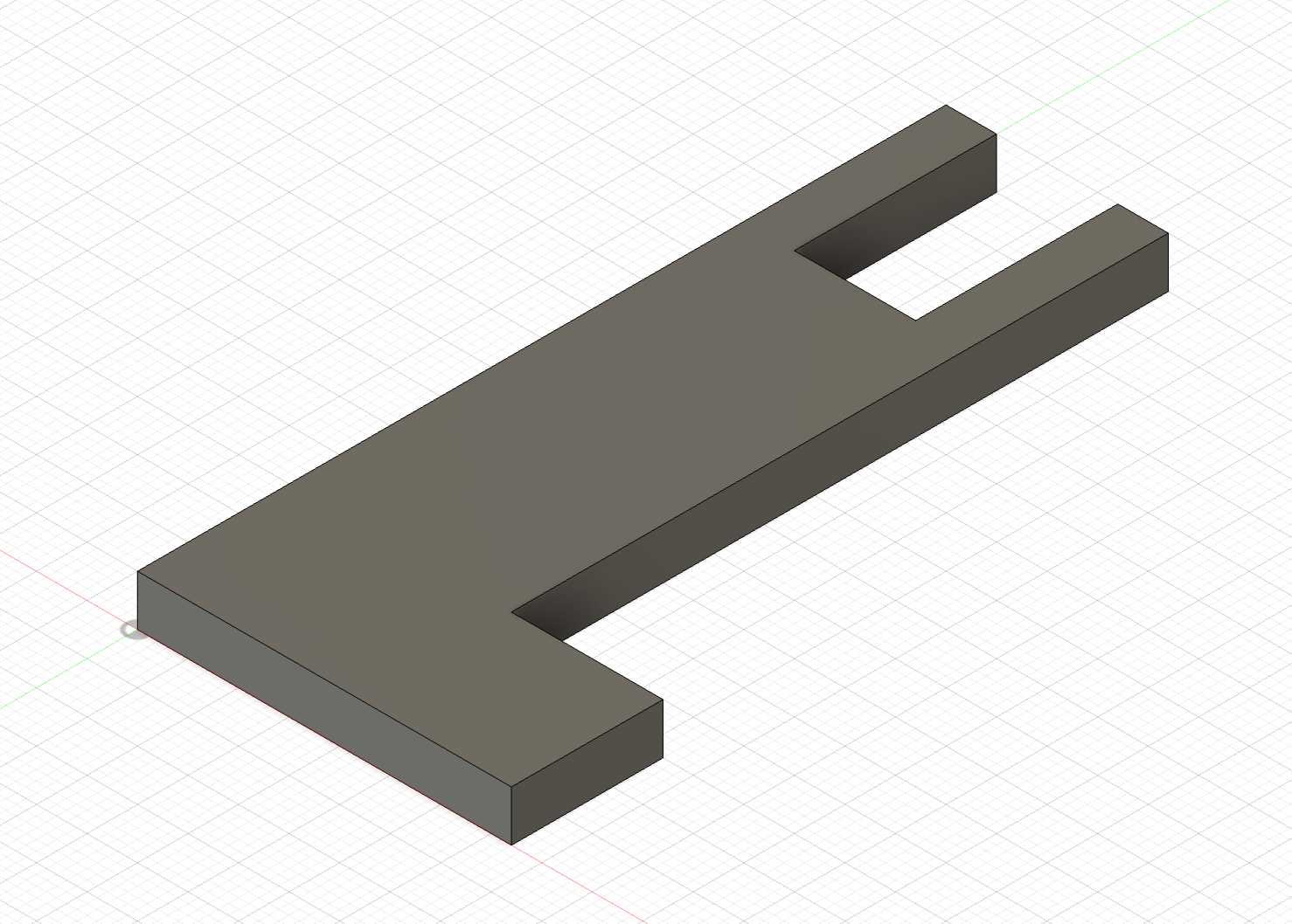
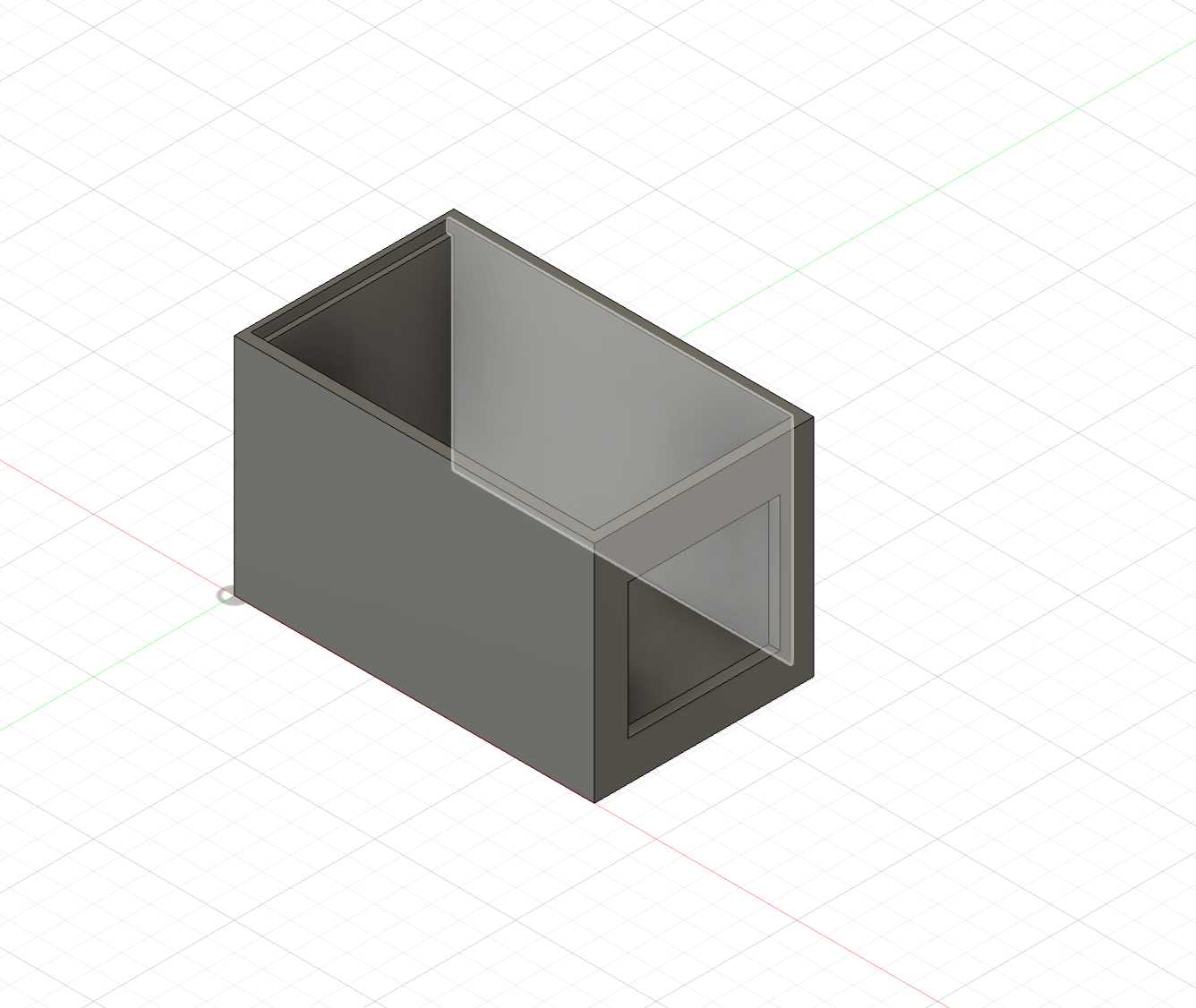
Frame:
For the frame, I used a laser cutter, cutting ¼ inch wood. I created a base, which I then superglued the other components onto. I also created a frame to hold the golf balls through 3D printing. After I printed my initial frame, I realized that I should have it at a slight angle so the golf balls slide to the start position and are ready to get hit by the motor. So, to do this, I printed a slightly angled base, which I glued the holder on. I then made walls with a laser cutter with holes for the camera and the golf balls to exit. I then closed the rest with a lid. After gluing the PCB board to the ground, I taped some surrounding wires down to give clearance for the motor.

Code I used:
Below is the space where I will add my code:
/* Includes ---------------------------------------------------------------- */
#include
#include "edge-impulse-sdk/dsp/image/image.hpp"
#include
#include "esp_camera.h"
// Select camera model - find more camera models in camera_pins.h file here
// https://github.com/espressif/arduino-esp32/blob/master/libraries/ESP32/examples/Camera/CameraWebServer/camera_pins.h
//#define CAMERA_MODEL_ESP_EYE // Has PSRAM
#define CAMERA_MODEL_AI_THINKER // Has PSRAM
#if defined(CAMERA_MODEL_AI_THINKER)
#define PWDN_GPIO_NUM 32
#define RESET_GPIO_NUM -1
#define XCLK_GPIO_NUM 0
#define SIOD_GPIO_NUM 26
#define SIOC_GPIO_NUM 27
#define Y9_GPIO_NUM 35
#define Y8_GPIO_NUM 34
#define Y7_GPIO_NUM 39
#define Y6_GPIO_NUM 36
#define Y5_GPIO_NUM 21
#define Y4_GPIO_NUM 19
#define Y3_GPIO_NUM 18
#define Y2_GPIO_NUM 5
#define VSYNC_GPIO_NUM 25
#define HREF_GPIO_NUM 23
#define PCLK_GPIO_NUM 22
#else
#error "Camera model not selected"
#endif
/* Constant defines -------------------------------------------------------- */
#define EI_CAMERA_RAW_FRAME_BUFFER_COLS 320
#define EI_CAMERA_RAW_FRAME_BUFFER_ROWS 240
#define EI_CAMERA_FRAME_BYTE_SIZE 3
Servo myservo;
const int servoPin = 14;
/* Private variables ------------------------------------------------------- */
static bool debug_nn = false; // Set this to true to see e.g. features generated from the raw signal
static bool is_initialised = false;
uint8_t *snapshot_buf; //points to the output of the capture
static camera_config_t camera_config = {
.pin_pwdn = PWDN_GPIO_NUM,
.pin_reset = RESET_GPIO_NUM,
.pin_xclk = XCLK_GPIO_NUM,
.pin_sscb_sda = SIOD_GPIO_NUM,
.pin_sscb_scl = SIOC_GPIO_NUM,
.pin_d7 = Y9_GPIO_NUM,
.pin_d6 = Y8_GPIO_NUM,
.pin_d5 = Y7_GPIO_NUM,
.pin_d4 = Y6_GPIO_NUM,
.pin_d3 = Y5_GPIO_NUM,
.pin_d2 = Y4_GPIO_NUM,
.pin_d1 = Y3_GPIO_NUM,
.pin_d0 = Y2_GPIO_NUM,
.pin_vsync = VSYNC_GPIO_NUM,
.pin_href = HREF_GPIO_NUM,
.pin_pclk = PCLK_GPIO_NUM,
//XCLK 20MHz or 10MHz for OV2640 double FPS (Experimental)
.xclk_freq_hz = 20000000,
.ledc_timer = LEDC_TIMER_0,
.ledc_channel = LEDC_CHANNEL_0,
.pixel_format = PIXFORMAT_JPEG, //YUV422,GRAYSCALE,RGB565,JPEG
.frame_size = FRAMESIZE_QVGA, //QQVGA-UXGA Do not use sizes above QVGA when not JPEG
.jpeg_quality = 12, //0-63 lower number means higher quality
.fb_count = 1, //if more than one, i2s runs in continuous mode. Use only with JPEG
.fb_location = CAMERA_FB_IN_PSRAM,
.grab_mode = CAMERA_GRAB_WHEN_EMPTY,
};
/* Function definitions ------------------------------------------------------- */
bool ei_camera_init(void);
void ei_camera_deinit(void);
bool ei_camera_capture(uint32_t img_width, uint32_t img_height, uint8_t *out_buf) ;
ei_impulse_result_t process_and_classify_image() {
ei_impulse_result_t result = {0};
// Create the signal structure
ei::signal_t signal;
signal.total_length = EI_CLASSIFIER_INPUT_WIDTH * EI_CLASSIFIER_INPUT_HEIGHT;
signal.get_data = &ei_camera_get_data;
// Capture image
if (!ei_camera_capture((size_t)EI_CLASSIFIER_INPUT_WIDTH, (size_t)EI_CLASSIFIER_INPUT_HEIGHT, snapshot_buf)) {
ei_printf("Failed to capture image\r\n");
return result;
}
// Run the classifier
EI_IMPULSE_ERROR err = run_classifier(&signal, &result, debug_nn);
if (err != EI_IMPULSE_OK) {
ei_printf("ERR: Failed to run classifier (%d)\n", err);
return result;
}
return result;
}
float get_first_bounding_box_confidence(const ei_impulse_result_t& result) {
const float MIN_CONFIDENCE = 0.5; // Minimum confidence threshold for valid detection
if (result.bounding_boxes_count > 0) {
for (uint32_t i = 0; i < result.bounding_boxes_count; i++) {
ei_impulse_result_bounding_box_t bb = result.bounding_boxes[i];
// Print debug info
ei_printf("Box %d: label=%s, confidence=%.3f\n", i, bb.label, bb.value);
// Only return confidence if it's above our minimum threshold
if (bb.value >= MIN_CONFIDENCE) {
return bb.value;
}
}
}
return 0.0f;
}
// Servo Functionality
bool firstLoop = true;
void performFirstLoop() {
// **First Iteration Behavior**
Serial.println("First Loop: Rotating Back");
myservo.writeMicroseconds(1300); // Rotate in desired direction
delay(100); // Rotate for 0.1 seconds
// Stop the servo after the initial movement
Serial.println("First Loop: Stopping");
myservo.writeMicroseconds(1500); // Stop
delay(500);
firstLoop = false;
// Pause for 0.5 seconds
}
void performRegularLoop() {
// **Regular Loop Behavior**
// Rotate Clockwise
Serial.println("Rotating Clockwise");
myservo.writeMicroseconds(1300); // Adjust for speed
delay(590); // Rotate for 5.5 seconds
// Stop
Serial.println("Stopping");
myservo.writeMicroseconds(1500); // Stop
delay(1000); // Pause for 1 second
// Rotate Counterclockwise
Serial.println("Rotating Counterclockwise");
myservo.writeMicroseconds(1700); // Adjust for speed
delay(580); // Rotate for 5.5 seconds
// Stop
Serial.println("Stopping");
myservo.writeMicroseconds(1500); // Stop
delay(1000); // Pause for 1 second
}
/**
* @brief Arduino setup function
*/
void setup()
{
// put your setup code here, to run once:
Serial.begin(115200);
//comment out the below line to start inference immediately after upload
myservo.attach(servoPin);
Serial.println("Servo SetUp complete!");
myservo.writeMicroseconds(1500); // Stop
delay(100); // Short delay to ensure the servo receives the command
while (!Serial);
Serial.println("Edge Impulse Inferencing Demo");
snapshot_buf = (uint8_t*)malloc(
EI_CAMERA_RAW_FRAME_BUFFER_COLS *
EI_CAMERA_RAW_FRAME_BUFFER_ROWS *
EI_CAMERA_FRAME_BYTE_SIZE);
if (snapshot_buf == NULL) {
ei_printf("Failed to allocate snapshot_buf memory!\r\n");
// Handle error: possibly return or halt, since we cannot proceed.
}
if (ei_camera_init() == false) {
ei_printf("Failed to initialize Camera!\r\n");
}
else {
ei_printf("Camera initialized\r\n");
}
ei_printf("\nStarting continious inference in 2 seconds...\n");
ei_sleep(2000);
}
/**
* @brief Get data and run inferencing
*
* @param[in] debug Get debug info if true
*/
void loop() {
Serial.printf("Free heap at start: %d bytes\n", esp_get_free_heap_size());
#if EI_CLASSIFIER_OBJECT_DETECTION == 1
const float DETECTION_THRESHOLD = 0.6; // Increased threshold for overall detection
const int NUM_READINGS = 3; // Match array size
float data[NUM_READINGS] = {0};
int valid_readings = 0;
float sum = 0.0f;
float ConfidenceBase =0.5f;
// Take measurements
for (int i = 0; i < NUM_READINGS; i++) {
ei_printf("\nTaking reading %d/%d...\n", i + 1, NUM_READINGS);
// Get classification result
ei_impulse_result_t result = process_and_classify_image();
// Get confidence value with higher threshold
float confidence = get_first_bounding_box_confidence(result);
if (confidence > ConfidenceBase) { // This now only triggers for confidences above MIN_CONFIDENCE
data[valid_readings] = confidence;
sum += confidence;
valid_readings++;
ei_printf("Valid confidence for reading %d: %.2f\n", i + 1, confidence);
} else {
ei_printf("No valid detection for reading %d\n", i + 1);
}
delay(300);
}
// Calculate average only if we have valid readings
float average = (valid_readings > 0) ? (sum / valid_readings) : 0.0f;
ei_printf("\nValid readings: %d\n", valid_readings);
ei_printf("Average confidence: %.2f\n", average);
if (average > DETECTION_THRESHOLD) {
ei_printf("Golf ball detected! Average confidence above threshold.\n");
} else {
performRegularLoop();
ei_printf("No reliable golf ball detection.\n");
}
Serial.printf("Free heap at end: %d bytes\n", esp_get_free_heap_size());
delay(1000);
#endif
}
/**
* @brief Setup image sensor & start streaming
*
* @retval false if initialisation failed
*/
bool ei_camera_init(void) {
if (is_initialised) return true;
#if defined(CAMERA_MODEL_ESP_EYE)
pinMode(13, INPUT_PULLUP);
pinMode(14, INPUT_PULLUP);
#endif
//initialize the camera
esp_err_t err = esp_camera_init(&camera_config);
if (err != ESP_OK) {
Serial.printf("Camera init failed with error 0x%x\n", err);
return false;
}
sensor_t * s = esp_camera_sensor_get();
// initial sensors are flipped vertically and colors are a bit saturated
if (s->id.PID == OV3660_PID) {
s->set_vflip(s, 1); // flip it back
s->set_brightness(s, 1); // up the brightness just a bit
s->set_saturation(s, 0); // lower the saturation
}
#if defined(CAMERA_MODEL_M5STACK_WIDE)
s->set_vflip(s, 1);
s->set_hmirror(s, 1);
#elif defined(CAMERA_MODEL_ESP_EYE)
s->set_vflip(s, 1);
s->set_hmirror(s, 1);
s->set_awb_gain(s, 1);
#endif
is_initialised = true;
return true;
}
/**
* @brief Stop streaming of sensor data
*/
void ei_camera_deinit(void) {
//deinitialize the camera
esp_err_t err = esp_camera_deinit();
if (err != ESP_OK)
{
ei_printf("Camera deinit failed\n");
return;
}
is_initialised = false;
return;
}
/**
* @brief Capture, rescale and crop image
*
* @param[in] img_width width of output image
* @param[in] img_height height of output image
* @param[in] out_buf pointer to store output image, NULL may be used
* if ei_camera_frame_buffer is to be used for capture and resize/cropping.
*
* @retval false if not initialised, image captured, rescaled or cropped failed
*
*/
bool ei_camera_capture(uint32_t img_width, uint32_t img_height, uint8_t *out_buf) {
bool do_resize = false;
if (!is_initialised) {
ei_printf("ERR: Camera is not initialized\r\n");
return false;
}
camera_fb_t *fb = esp_camera_fb_get();
if (!fb) {
ei_printf("Camera capture failed\n");
return false;
}
bool converted = fmt2rgb888(fb->buf, fb->len, PIXFORMAT_JPEG, snapshot_buf);
esp_camera_fb_return(fb);
if(!converted){
ei_printf("Conversion failed\n");
return false;
}
if ((img_width != EI_CAMERA_RAW_FRAME_BUFFER_COLS)
|| (img_height != EI_CAMERA_RAW_FRAME_BUFFER_ROWS)) {
do_resize = true;
}
if (do_resize) {
ei::image::processing::crop_and_interpolate_rgb888(
out_buf,
EI_CAMERA_RAW_FRAME_BUFFER_COLS,
EI_CAMERA_RAW_FRAME_BUFFER_ROWS,
out_buf,
img_width,
img_height);
}
return true;
}
static int ei_camera_get_data(size_t offset, size_t length, float *out_ptr)
{
// we already have a RGB888 buffer, so recalculate offset into pixel index
size_t pixel_ix = offset * 3;
size_t pixels_left = length;
size_t out_ptr_ix = 0;
while (pixels_left != 0) {
// Swap BGR to RGB here
// due to https://github.com/espressif/esp32-camera/issues/379
out_ptr[out_ptr_ix] = (snapshot_buf[pixel_ix + 2] << 16) + (snapshot_buf[pixel_ix + 1] << 8) + snapshot_buf[pixel_ix];
// go to the next pixel
out_ptr_ix++;
pixel_ix+=3;
pixels_left--;
}
// and done!
return 0;
}
#if !defined(EI_CLASSIFIER_SENSOR) || EI_CLASSIFIER_SENSOR != EI_CLASSIFIER_SENSOR_CAMERA
#error "Invalid model for current sensor"
#endif