Group and Individual Assignment
Group Assignment:
Use the test equipment in your lab to observe the operation of a microcontroller circuit board
For the group assignment this week, I experimented with some of the equipment in the REEF. I worked with David, Sara, Alex, and Namirah. Initially, we were not sure what we should do, so we started out by first finding a microcontroller circuit board. We used the Seeed Studio Xiao esp32C3 because it was simple to hook up to the breadboard and had USB-C connectivity to our computers.
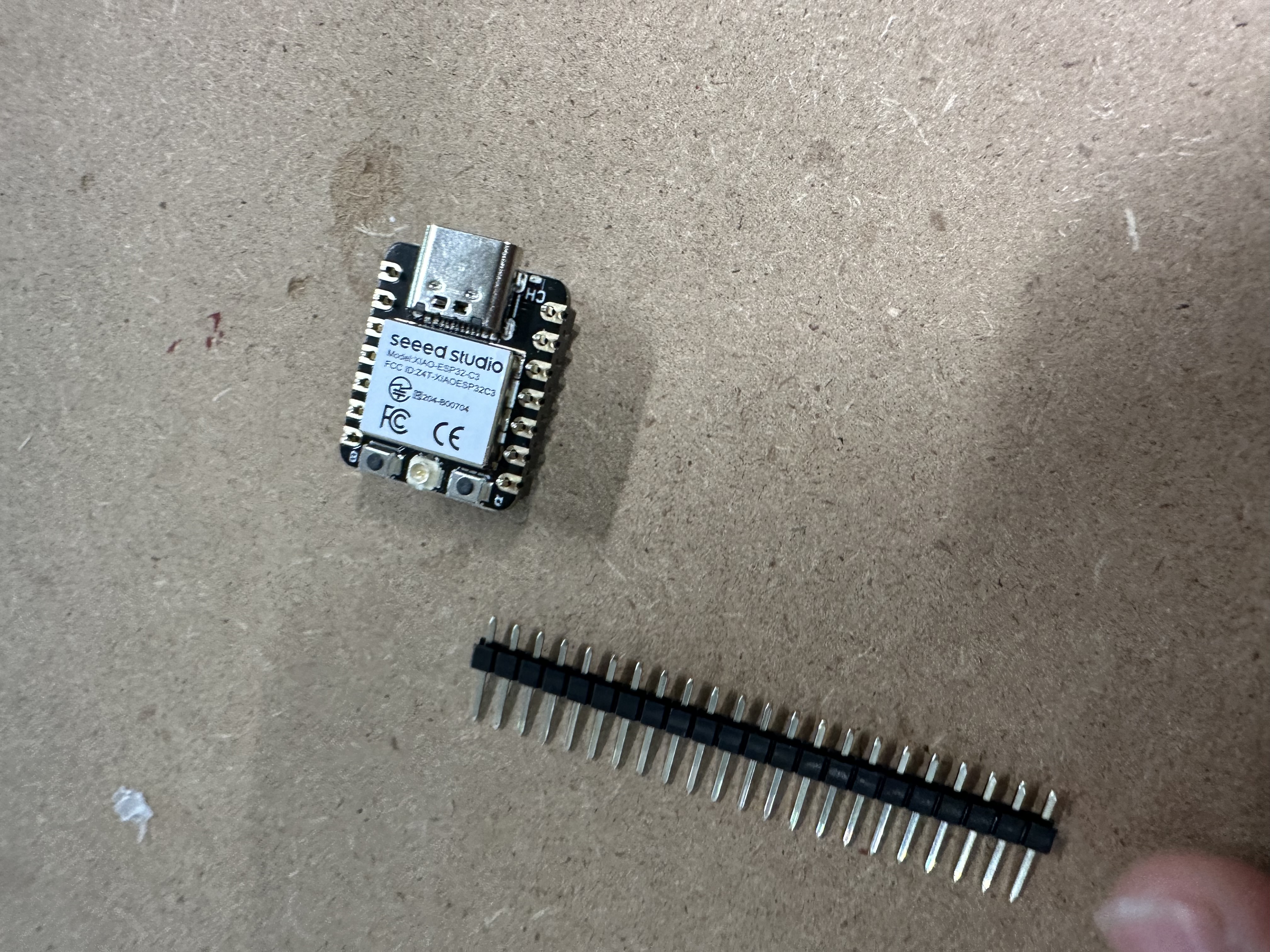
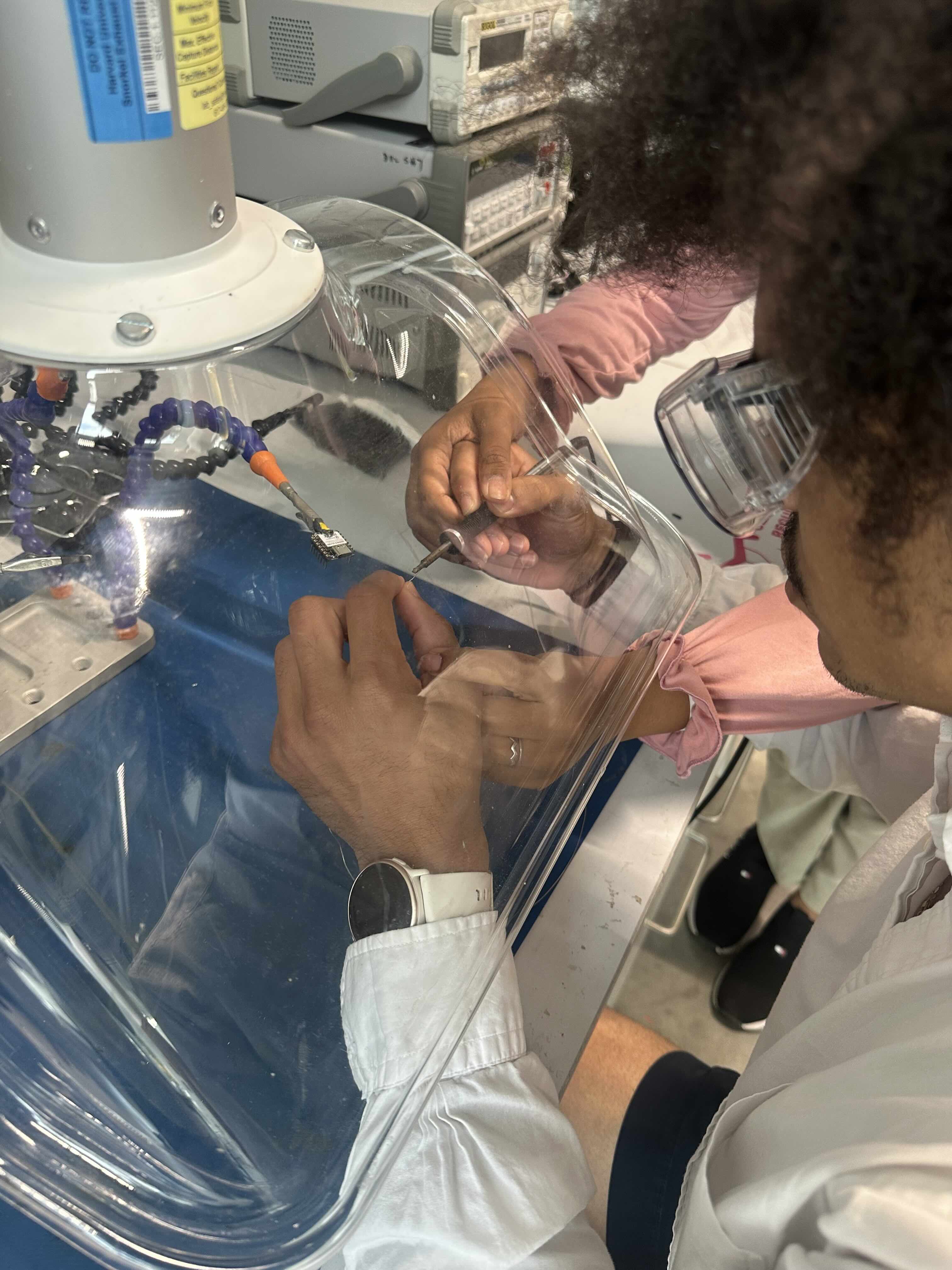
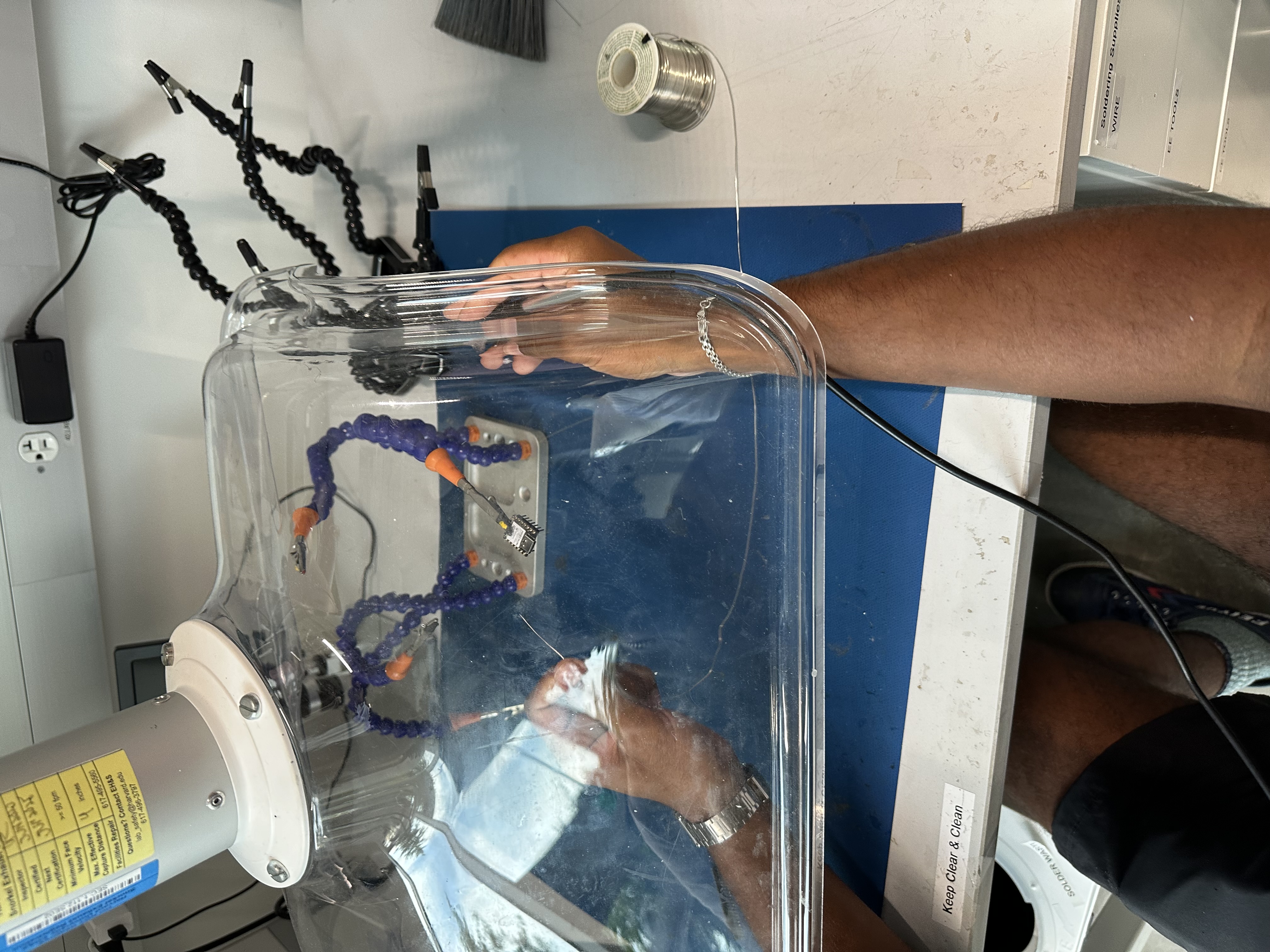
We started by using the soldering equipment in the REEF to solder the microcontroller to sticks, which we could then put on the breadboard. I know they are not called sticks, but I have forgotten their real names. Basically, the things that go through the holes and help attach. This soldering process was certainly a learning process and reminded me a bit of welding in my construction job last summer.
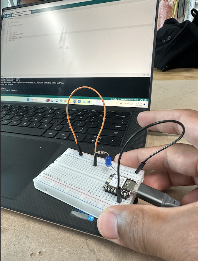
After completing this solder, we then wired a breadboard and wrote code to make an LED light blink on the breadboard. We were successful with this initial test.
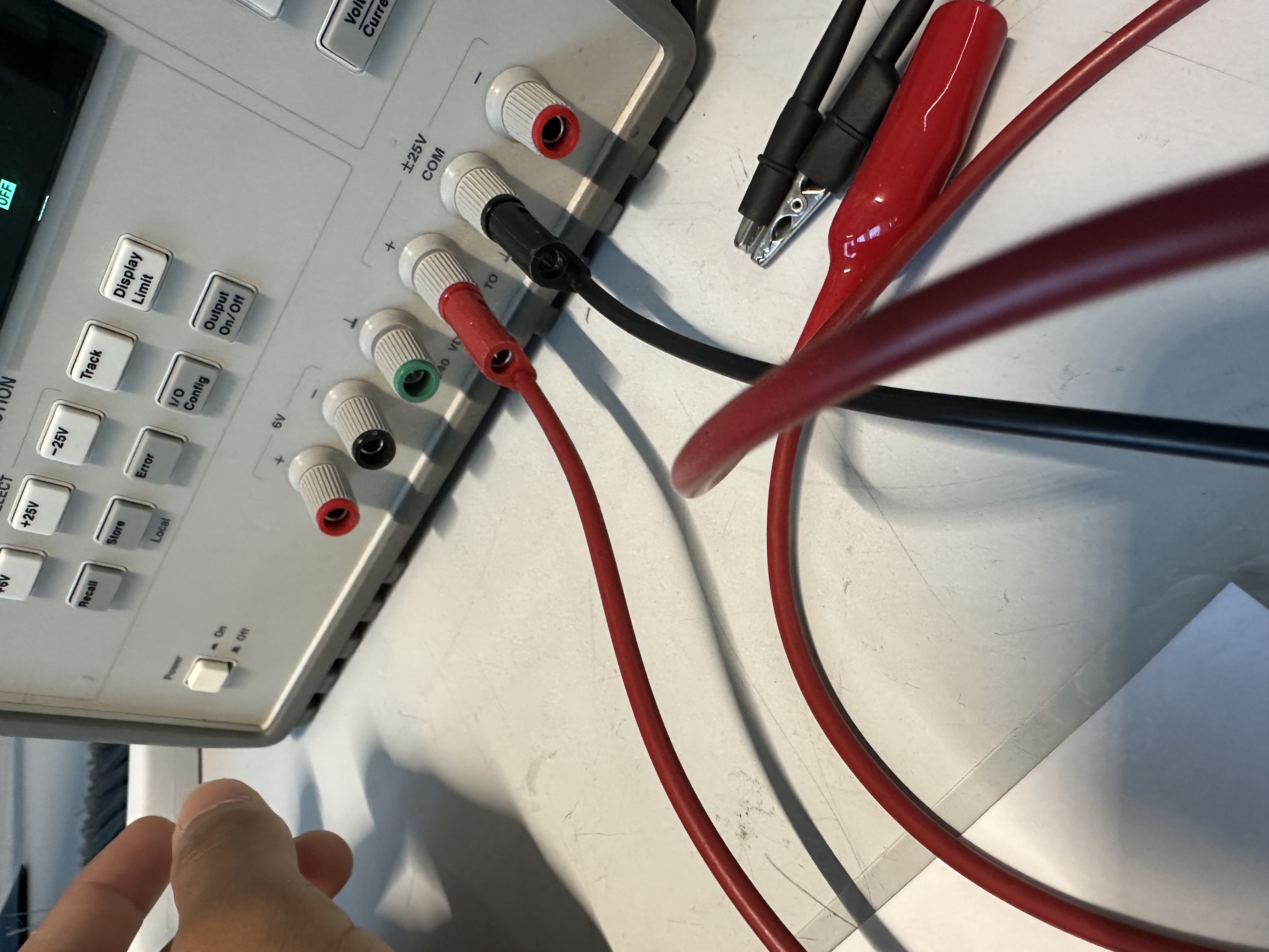
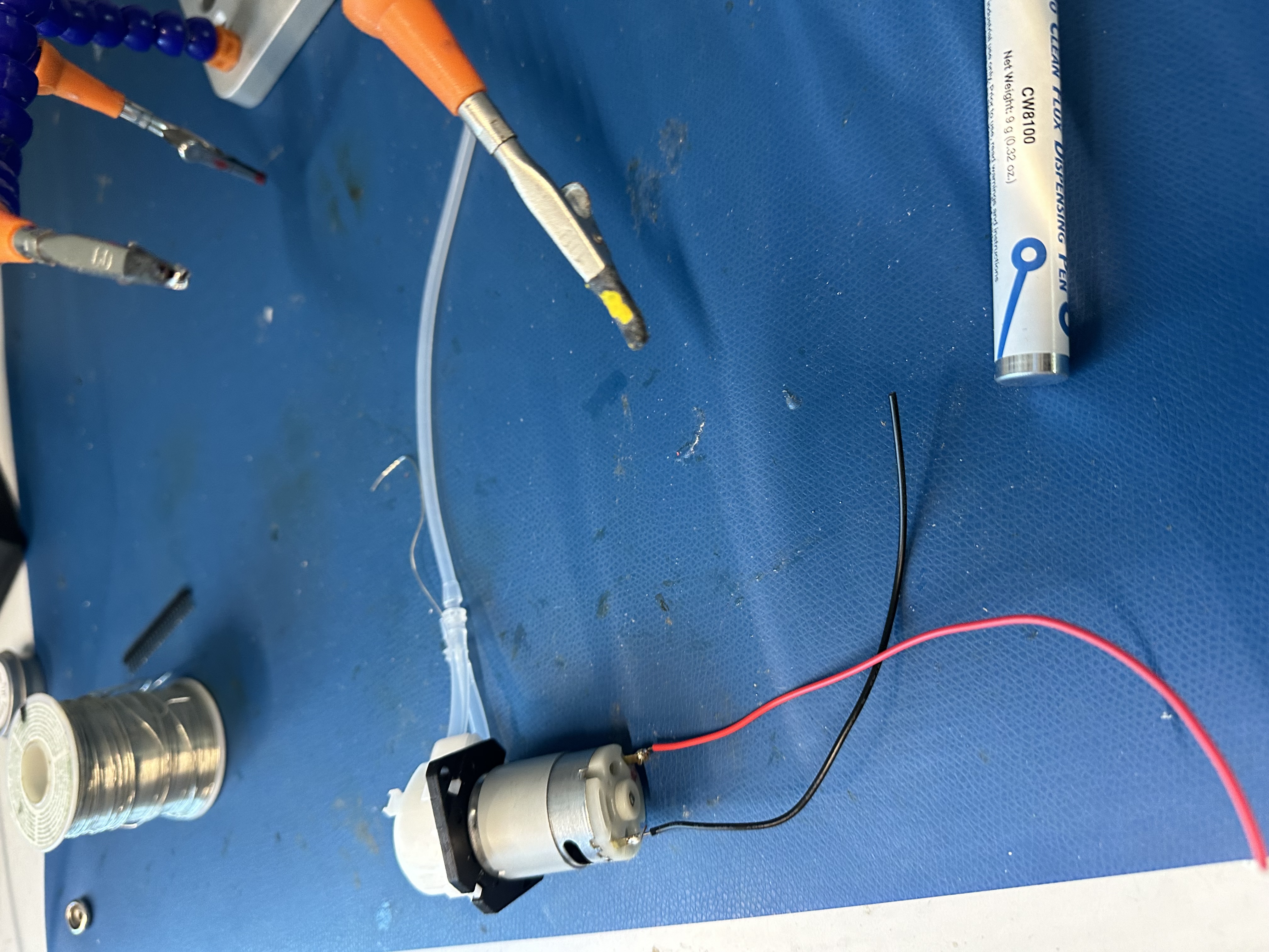
I then decided to test out a pump with the power supply in the REEF. Because I will need a pump for my project, I was trying to start prototyping with one. I borrowed a friend's 12 V pump for this test, which is shown below. I discovered that this motor will run at as little as 3 V, which is perfect for connecting to a Xiao or Pi Pico Board.
Individual Assignment:
Use an EDA tool to design a development board to interact and communicate with an embedded microcontroller
I am completely new to electronics and literally understood nothing about the assignment this week. So I ended up going to YouTube to try and learn some stuff. I initially was looking up PCB courses to try and take some, and Altium had some. However, I cannot download this on my Mac, so I figured I might as well use KiCad or Eagle. KiCad seemed pretty simple, so I ended up using it.
I did not even know what schematics were, so the first video I watched was on how they are structured. The Link is here: YouTube Video.
This was extremely helpful in learning what symbols were. Further, for all the individual schematic symbols, I was able to look things up for them to understand what they are, such as resistors, capacitors, and more.
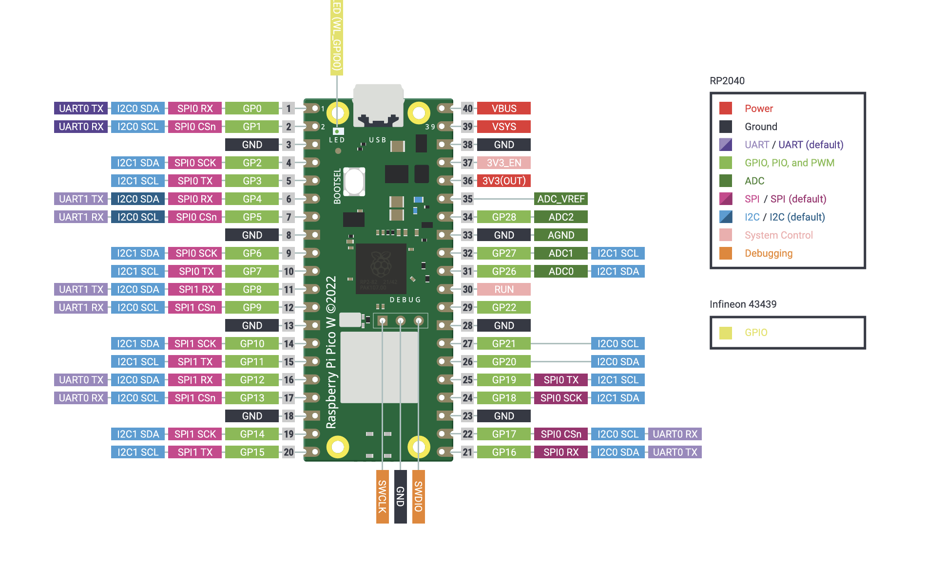
I then watched this video on the Pi Pico to understand more about the microcontroller. I should have done this last week. That would have helped a lot. Nevertheless, it was still extremely useful now. YouTube Video on Pi Pico
What really clicked for me was realizing that a PCB board is just a slicker breadboard, or at least that is how it works in my head. I then got to designing.
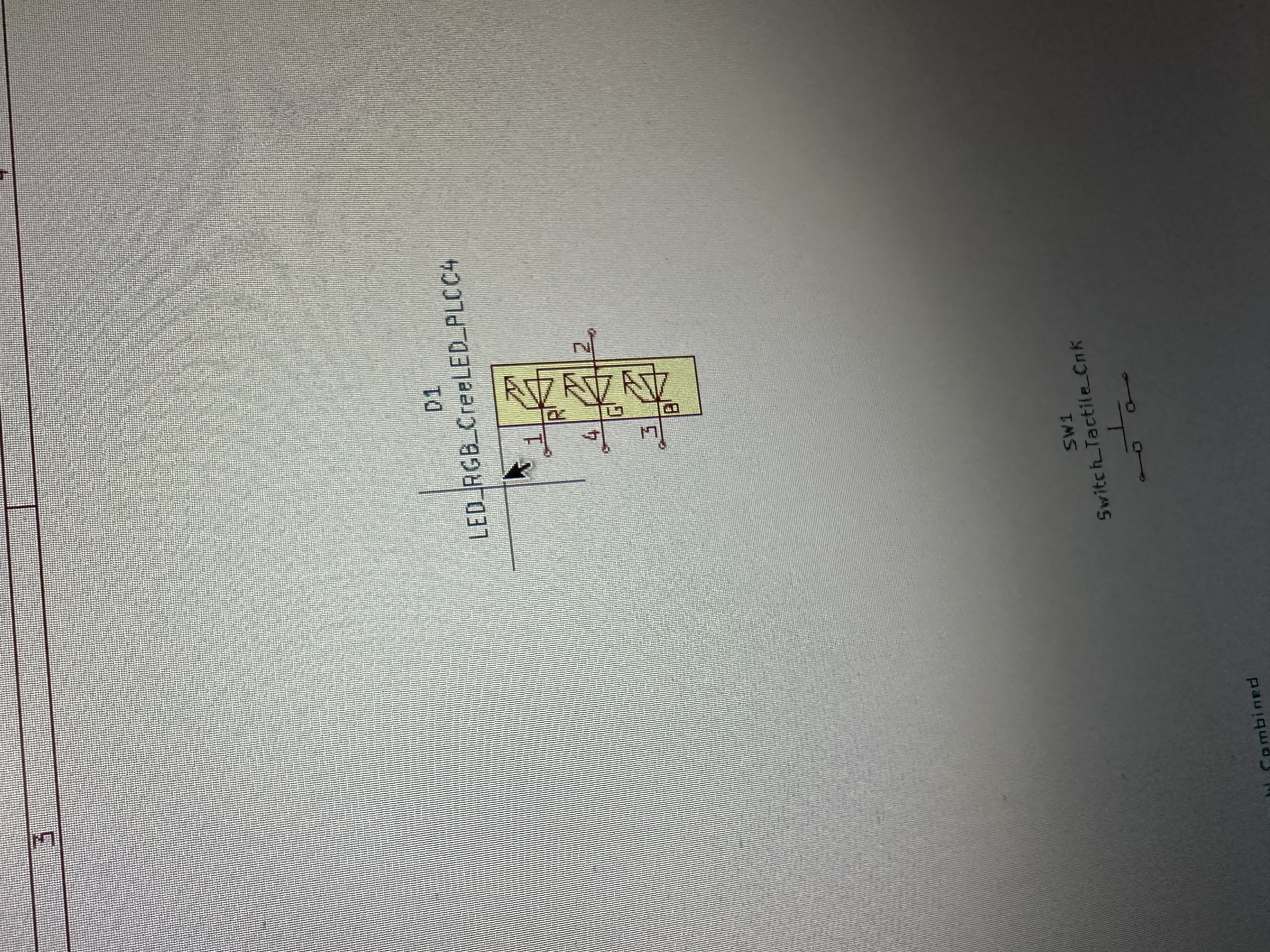
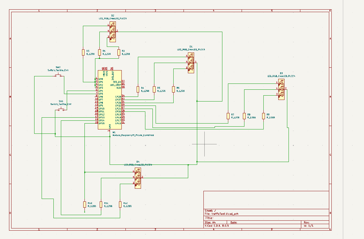
I started by plotting out an idea. I wanted to be able to simulate building a traffic intersection with my PCB board. I got to designing and decided to use a 3-color LED light to act as it. It is RGB, so blue will just have to act as yellow for now. I downloaded KiCad and then libraries for it and started getting my materials on the schematic.
I decided to go with the Pi Pico because I was comfortable with it after watching the YouTube video and felt that I understood how its connections worked.
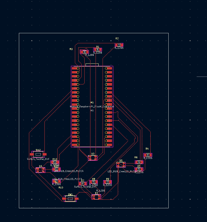
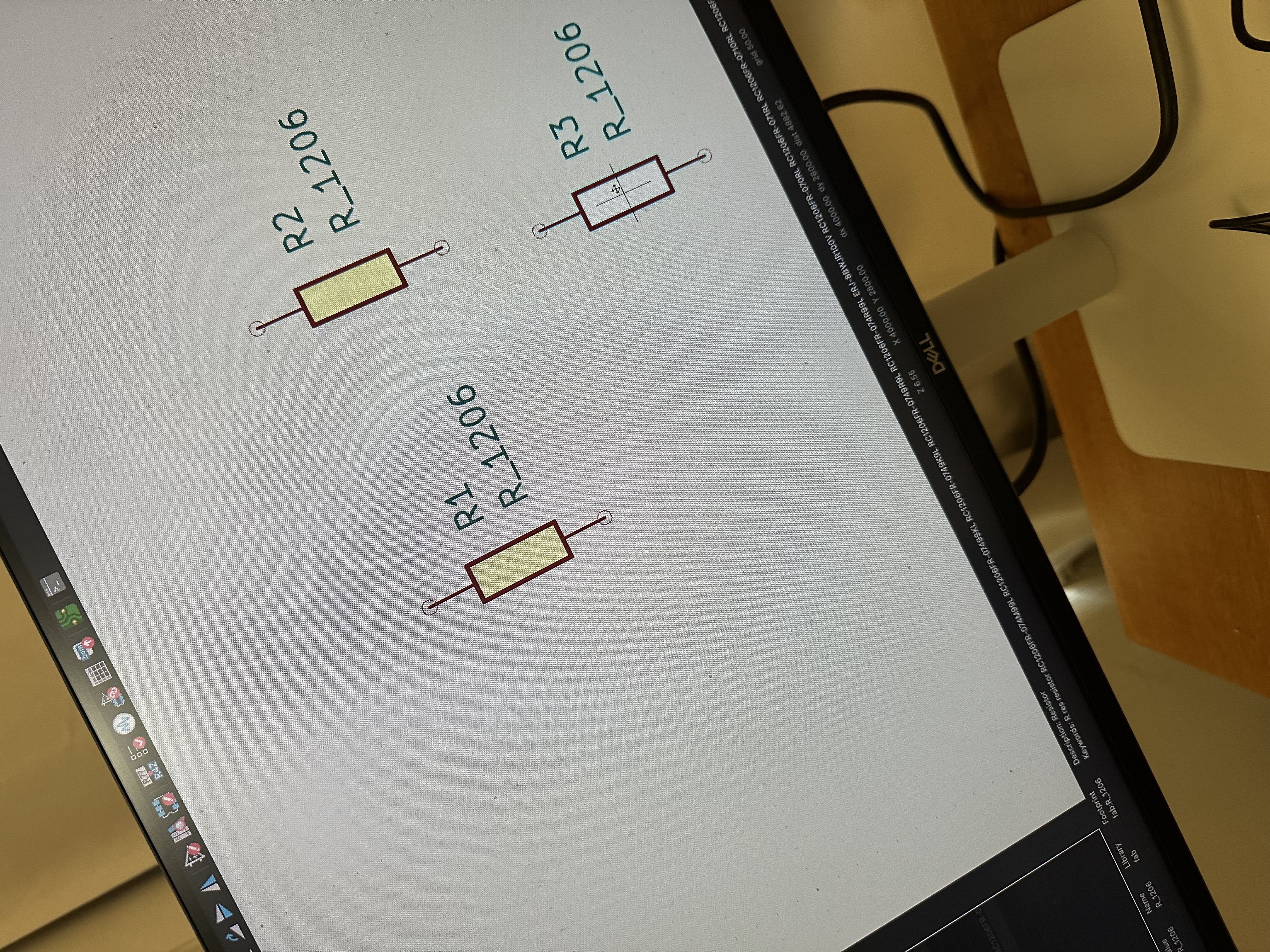
I started by dragging out the resistors onto the schematic and the lights. I needed 3 resistors for every RGB LED. I then attached everything to different GIPO pins on the Pi Pico and then to ground. I also added buttons to act as the buttons pedestrians push on the street.
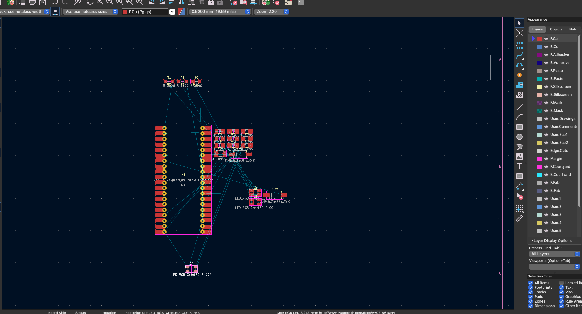
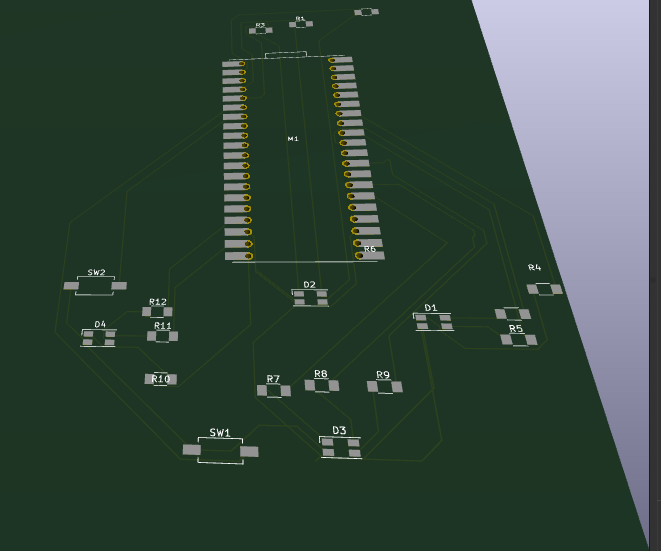
After I designed my schematic, I pushed it out to the PCB design tool. I did not realize initially that each line could not touch one another, so I spent a bit of time dragging and re-dragging things, then re-editing in my schematic to make sure the connections worked. However, they ultimately did. It ended up being quite challenging because I wanted my LEDs to be placed around each other on the final PCB board. I was also initally confused as to what reppresentaded the ground ports on the PCB but after looking at the datasheet I realized which are which