Week 6 Reflection
Reflection:
This week was pretty challenging since I am new to electronics. If I am called on in class, I know I did not finish but I promise I will not fall behind. Anyway, to get into it.
I started by watching a bunch of YouTube videos on how to read schematics and how to power a motor with a Xiao ESP32C3.
I was going to do the board I did for the project last week, however, when I designed it, the lines/traces were too small and we also did not have the parts. So instead of re-doing that, I decided to try something for my project.
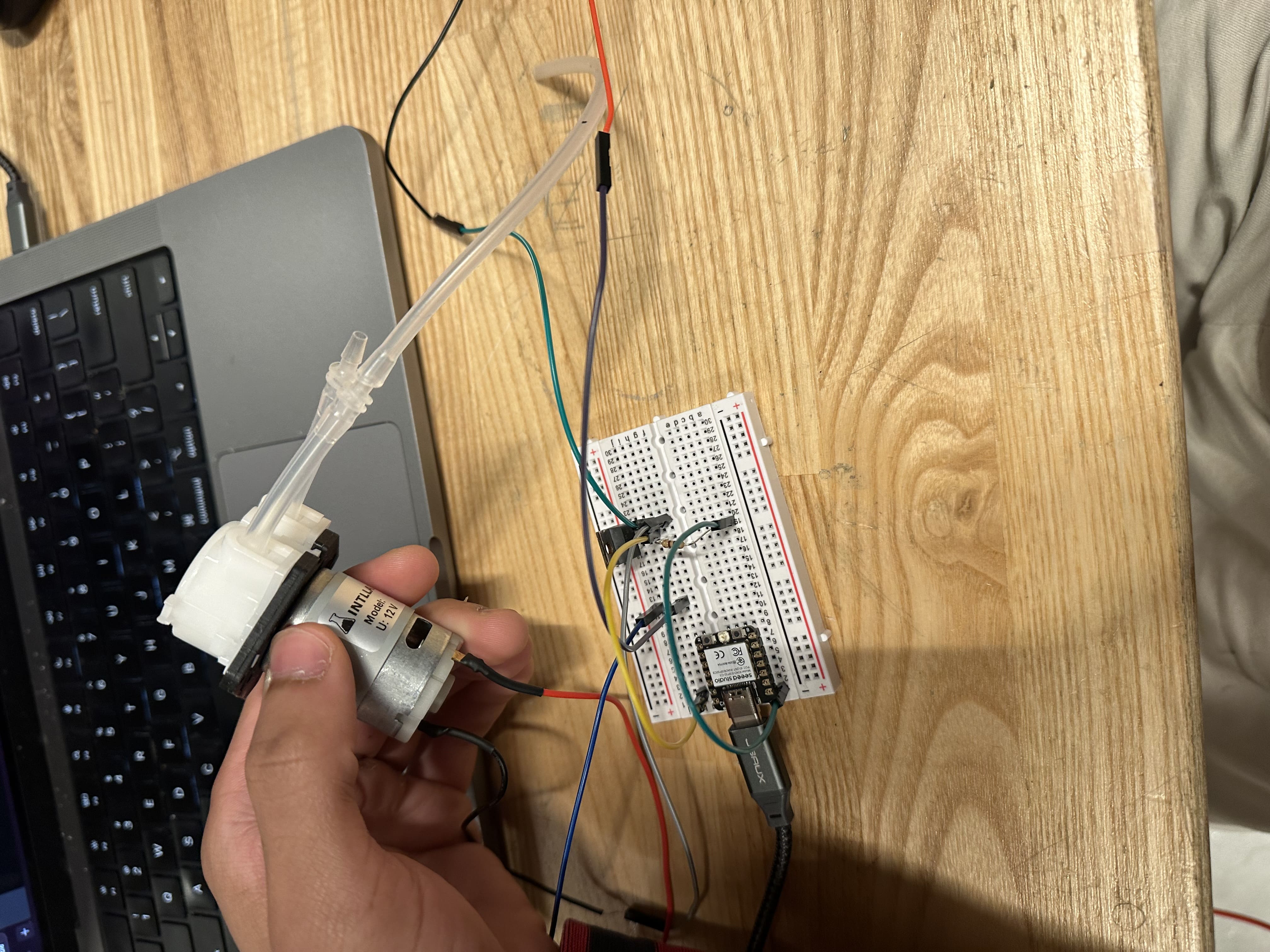
I basically wanted to prototype the process of getting a motor to work since I would need a motor to deliver nicotine onto a patch. While I would need a much smaller motor to make the patch easily wearable, I figured it would still be good to start working with motors.
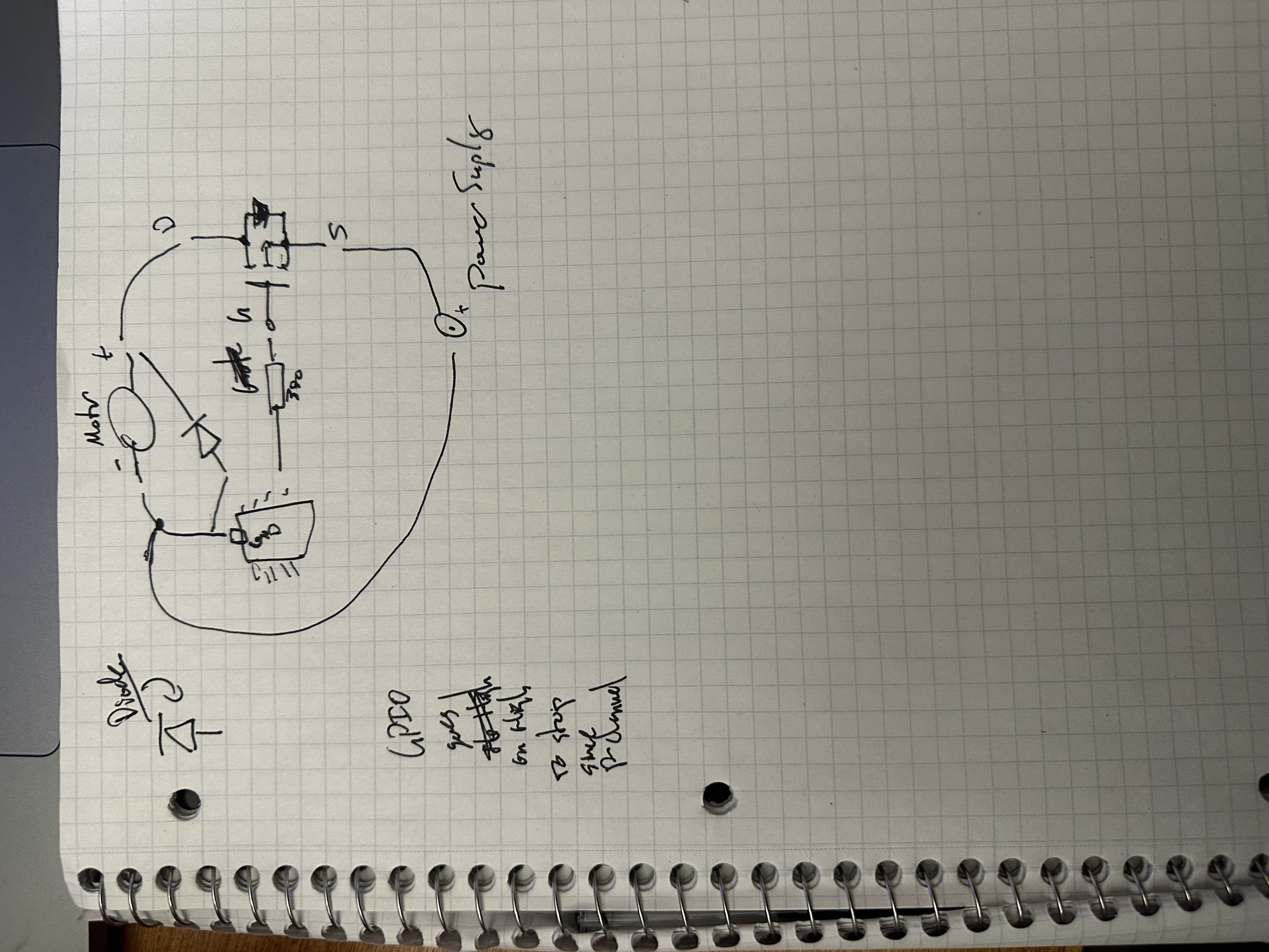
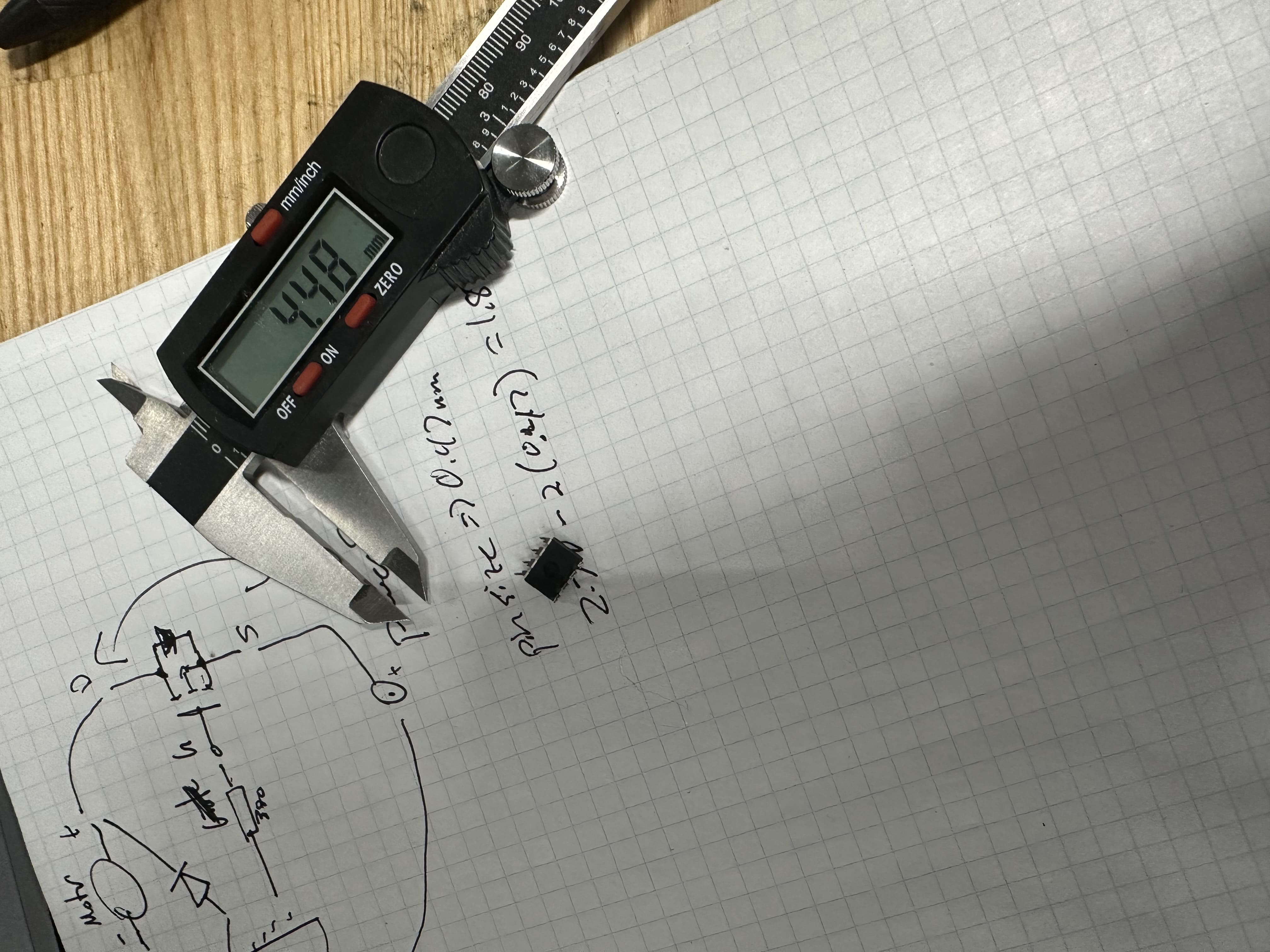
I did a bunch of research into how I could get a Xiao to power a 12V motor and realized that I needed a MOSFET, which is an item that allows a small amount of voltage to establish the connection between the 12V DC motor and its power source. I drew out how my schematics should look to try to understand what I was doing better.
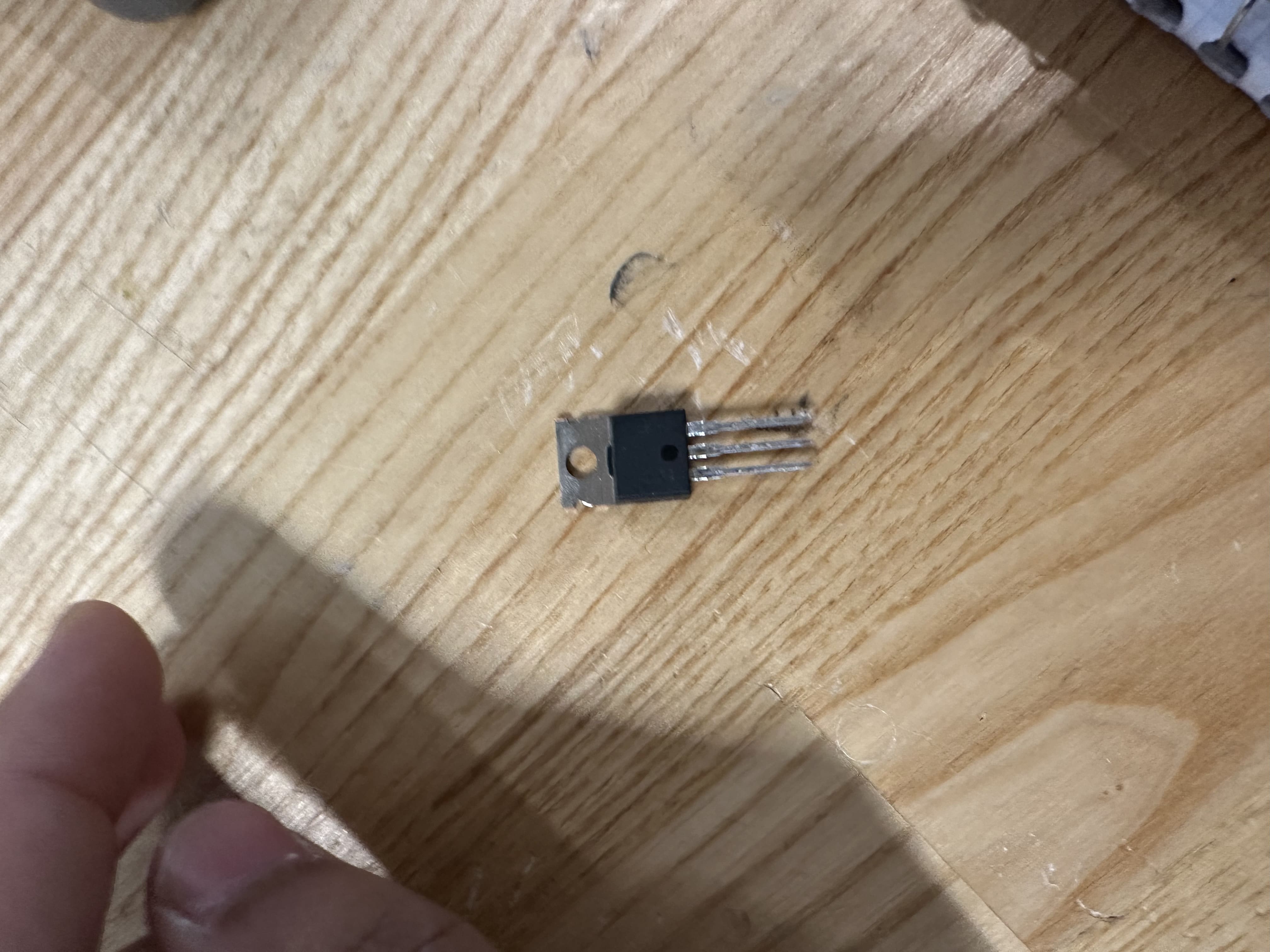
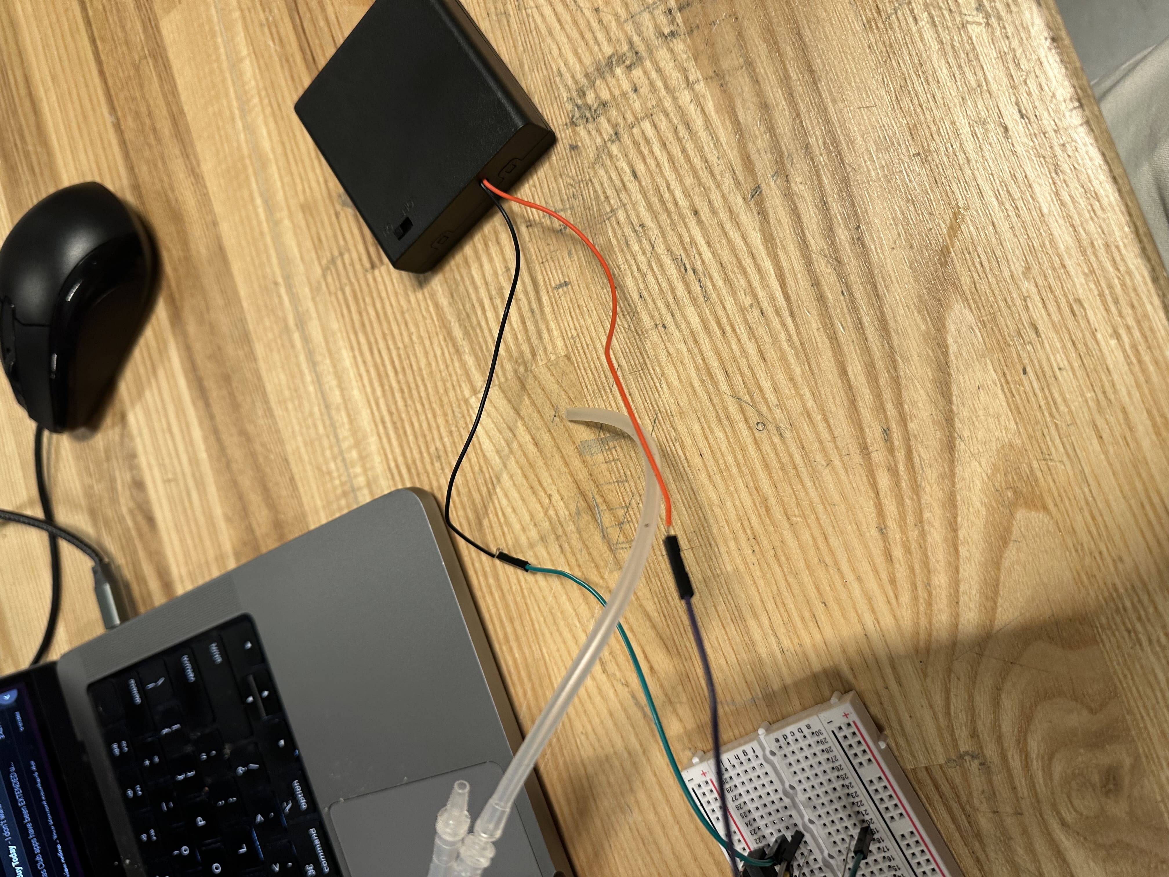
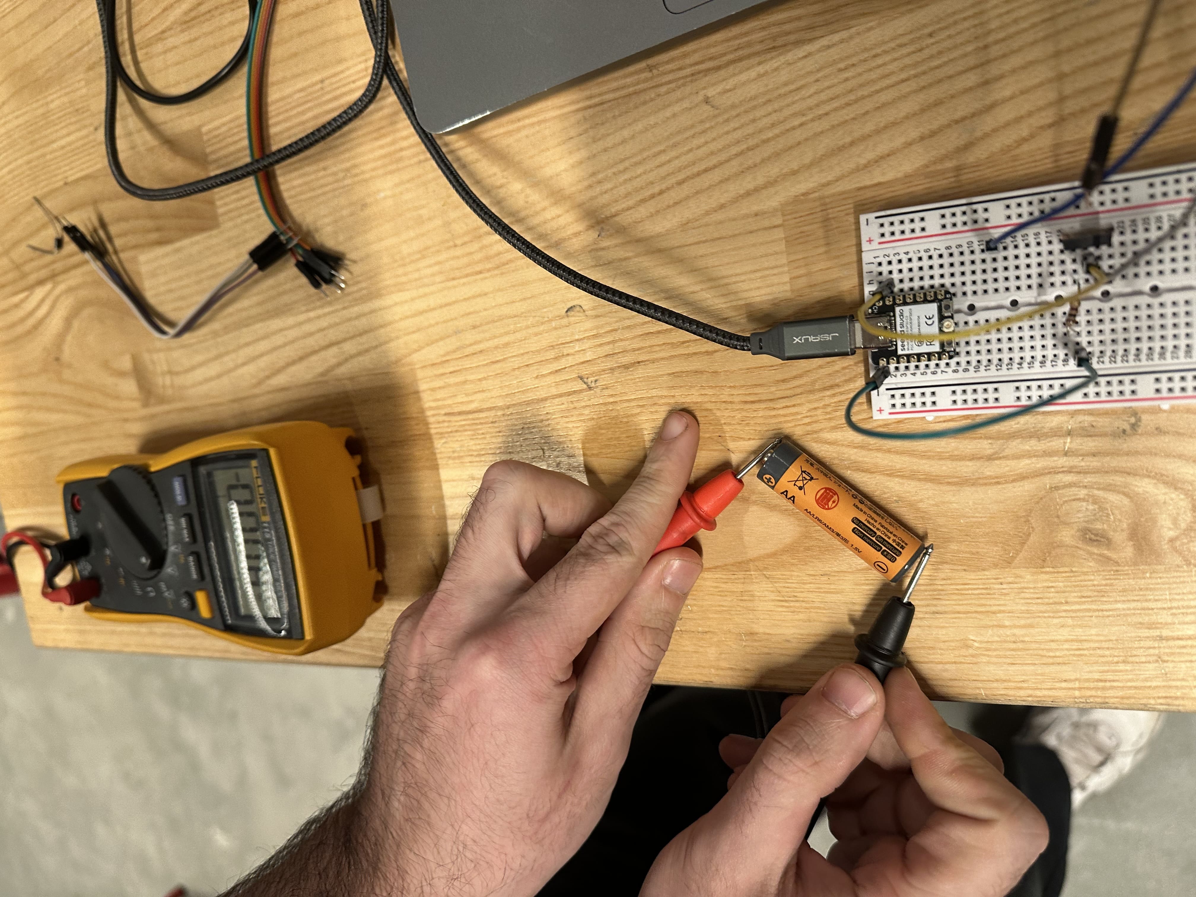
I tried to use a MOSFET I found and measure it out, but eventually realized that it was not in the KiCad component. I found another MOSFET that worked for the breadboard test. I tested the 12V motor with the power source in the lab and it worked, so I got started. I tried doing this with a battery on the breadboard, but the battery connections were pretty faulty, and I could not get them to work. This took me an absurd amount of time to figure out.
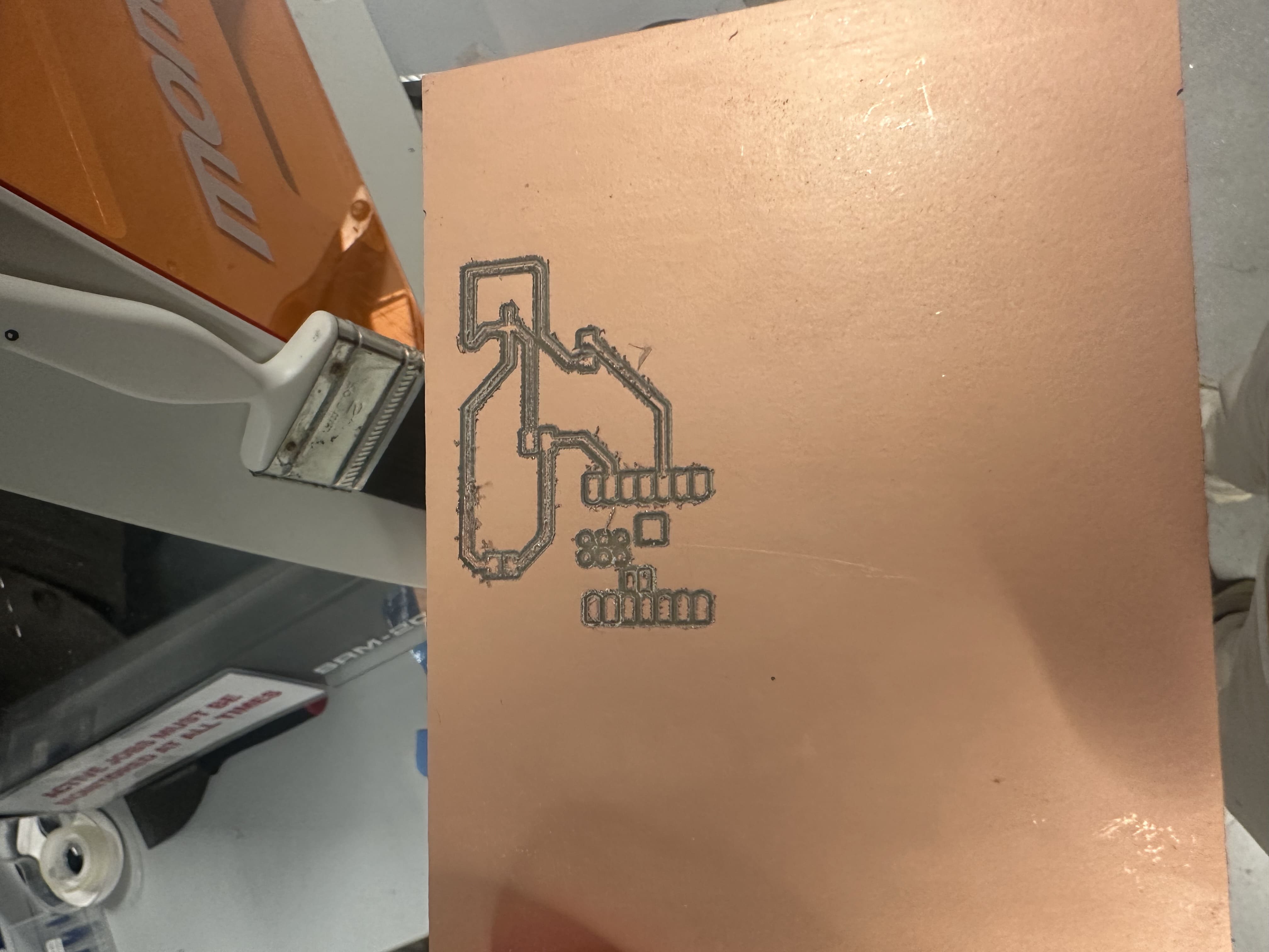
So I started drawing out the schematic, which was not terribly difficult after finding out which parts we had in the lab that were also in KiCad. I also found a smaller MOSFET in the KiCad library which I can solder on. After making this design, I drew out the traces on the PCB editor then got the thing uploaded to MODs.
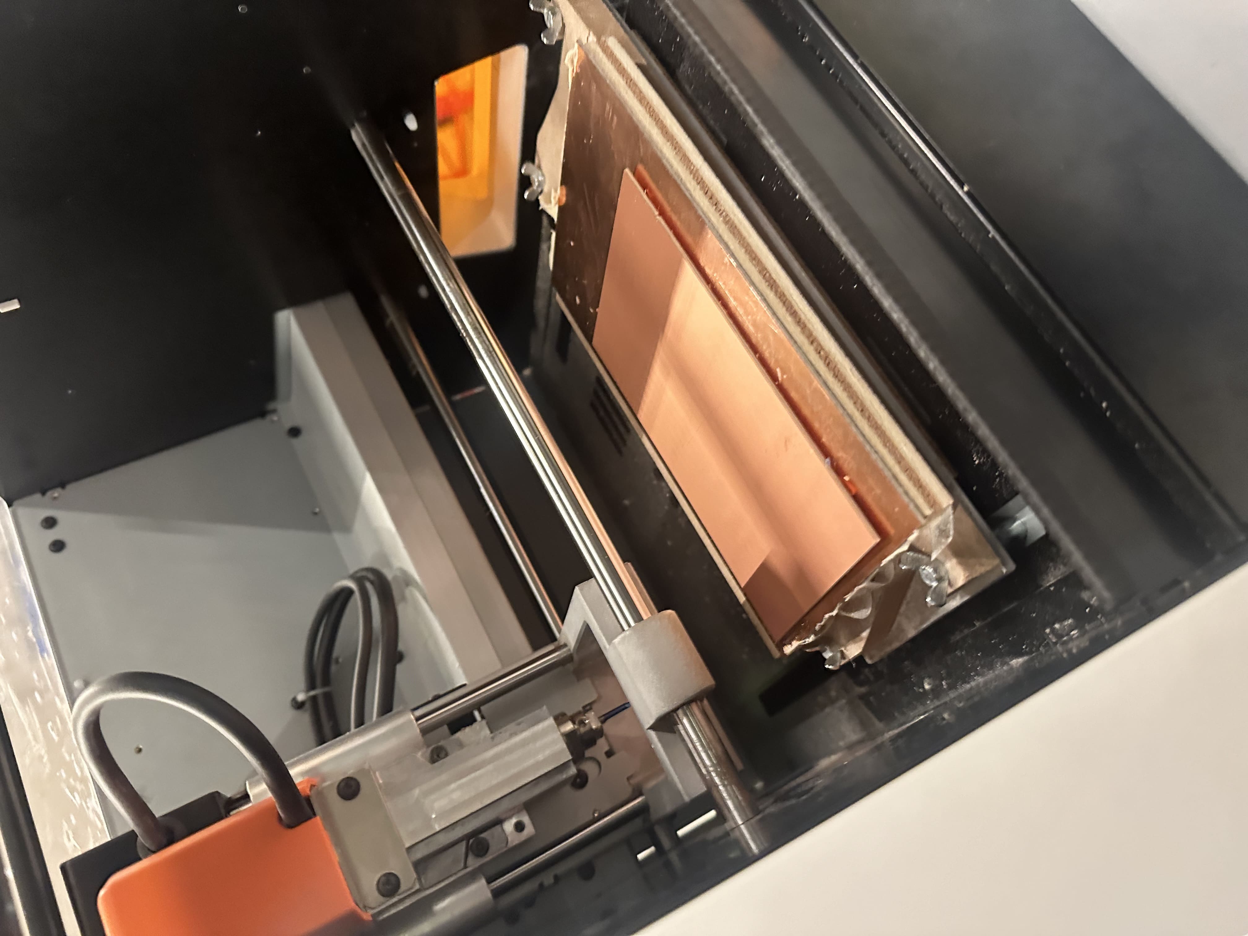
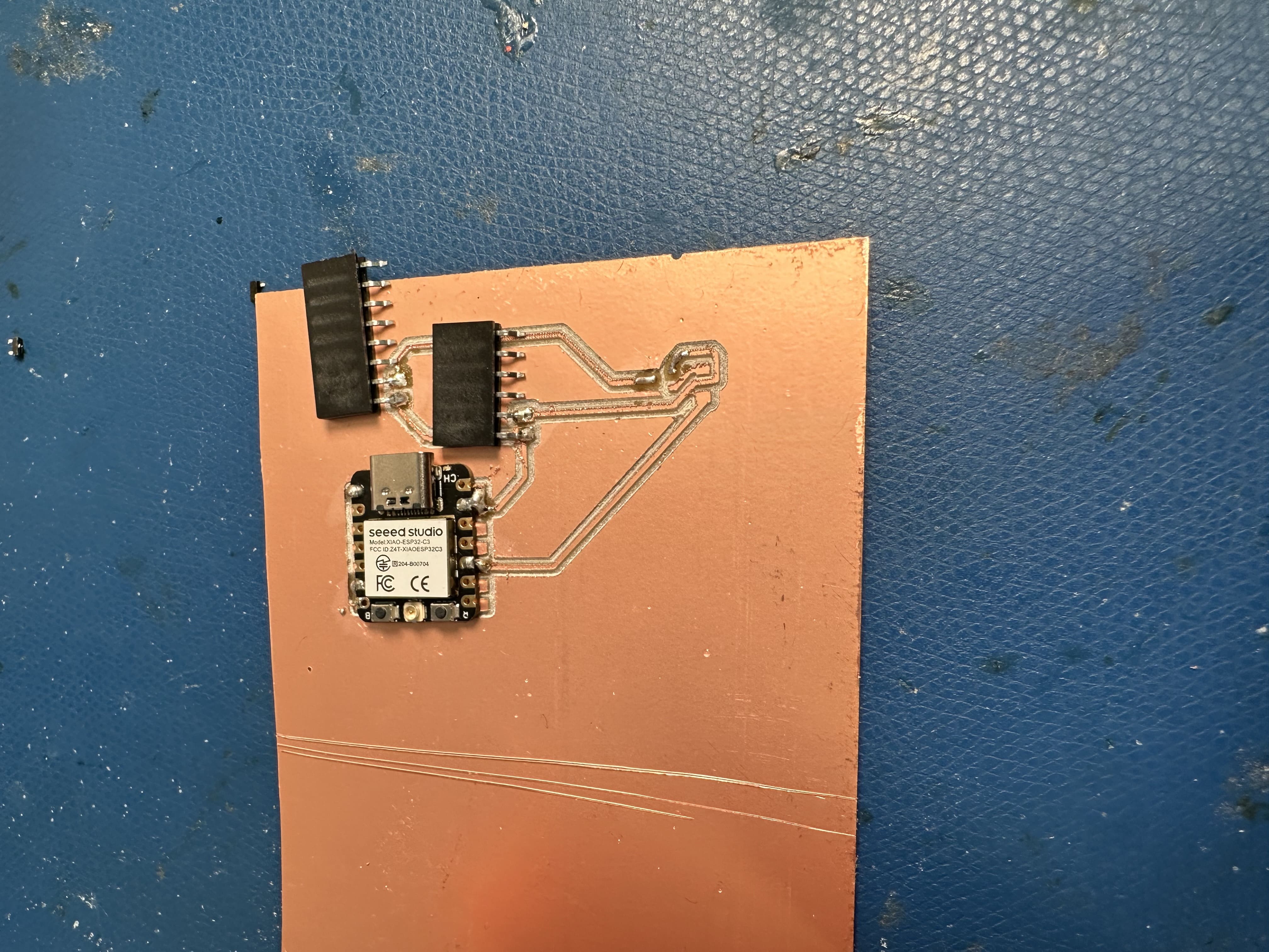
Leo helped show me how the mill worked and how to get it set up. I eventually milled out my PCB board after missing one up and then attempted to solder. I could solder on the microcontroller and the headers I was going to use to connect the pump and power source to, but I could not figure out how to connect the minute pieces on. I will figure this out at office hours soon, but right now I have this.
PCB I can work with:
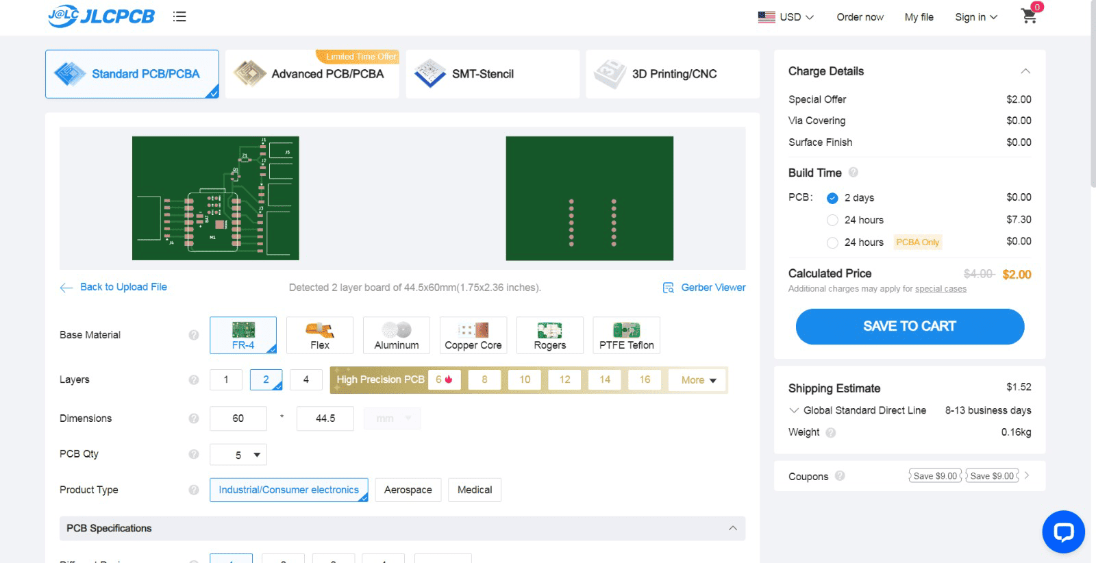
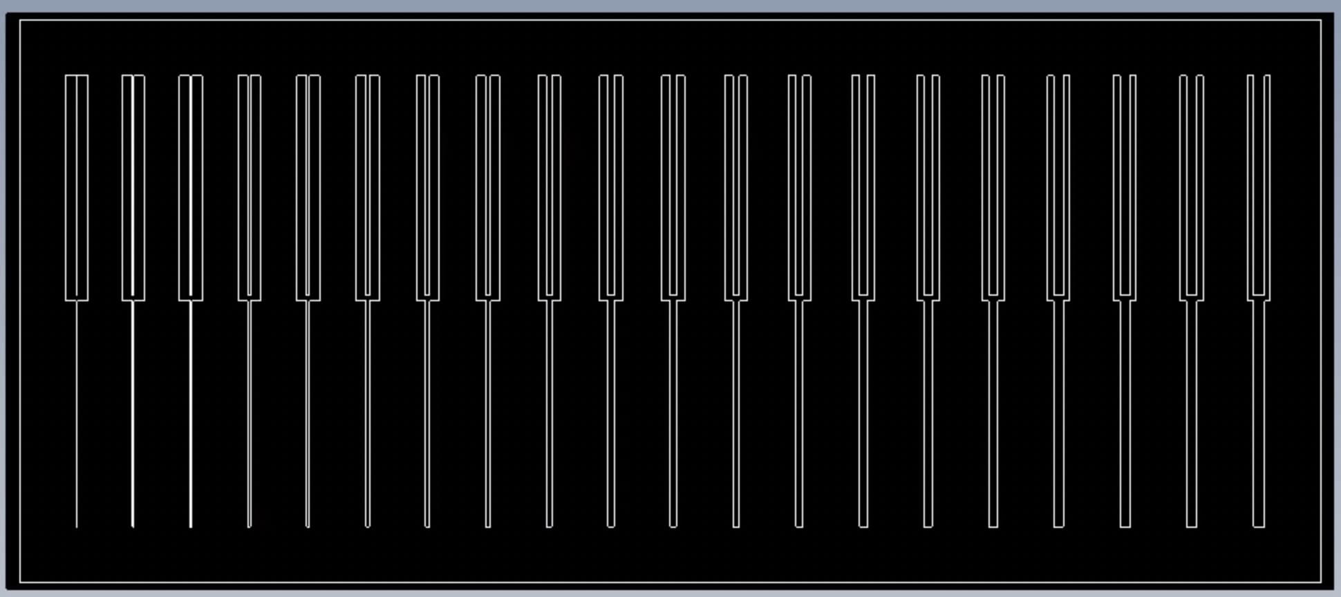
Group Assignment:
For the group assignment this week, I worked with David, Alex, Sara, and Namirah. We used CAD to model out the test measurements for a board which is shown below. Our ranges for the widths of the cuts are from 0.001 to 0.020 by increments of 0.001. Furhter, Alex ordered his board and went through the process with us of how he did so. I will probably order my board in the future, I just did not have time to do it this week