Week 11: Networking
For Networking Week I wanted to get a simple MVP of my final project together with sockets and headers instead of pogo pins (because I still cannot get a reliable connection with them)
First I redesigned my pcbs to be able to work with pin and sockets instead of pogo pins. Changing the puzzle piece to work was pretty trivial as the top stayed the same as the previous design and I just just had to modify the bottom of the puzzle piece to allow header pins to stick out of the bottom. While the puzzle piece bottom needed to be double sided because I had header pins going up to connect it to the upper board and pins going down to connect it to the main grid, I had figure that out how to mill double sided boards during output week.
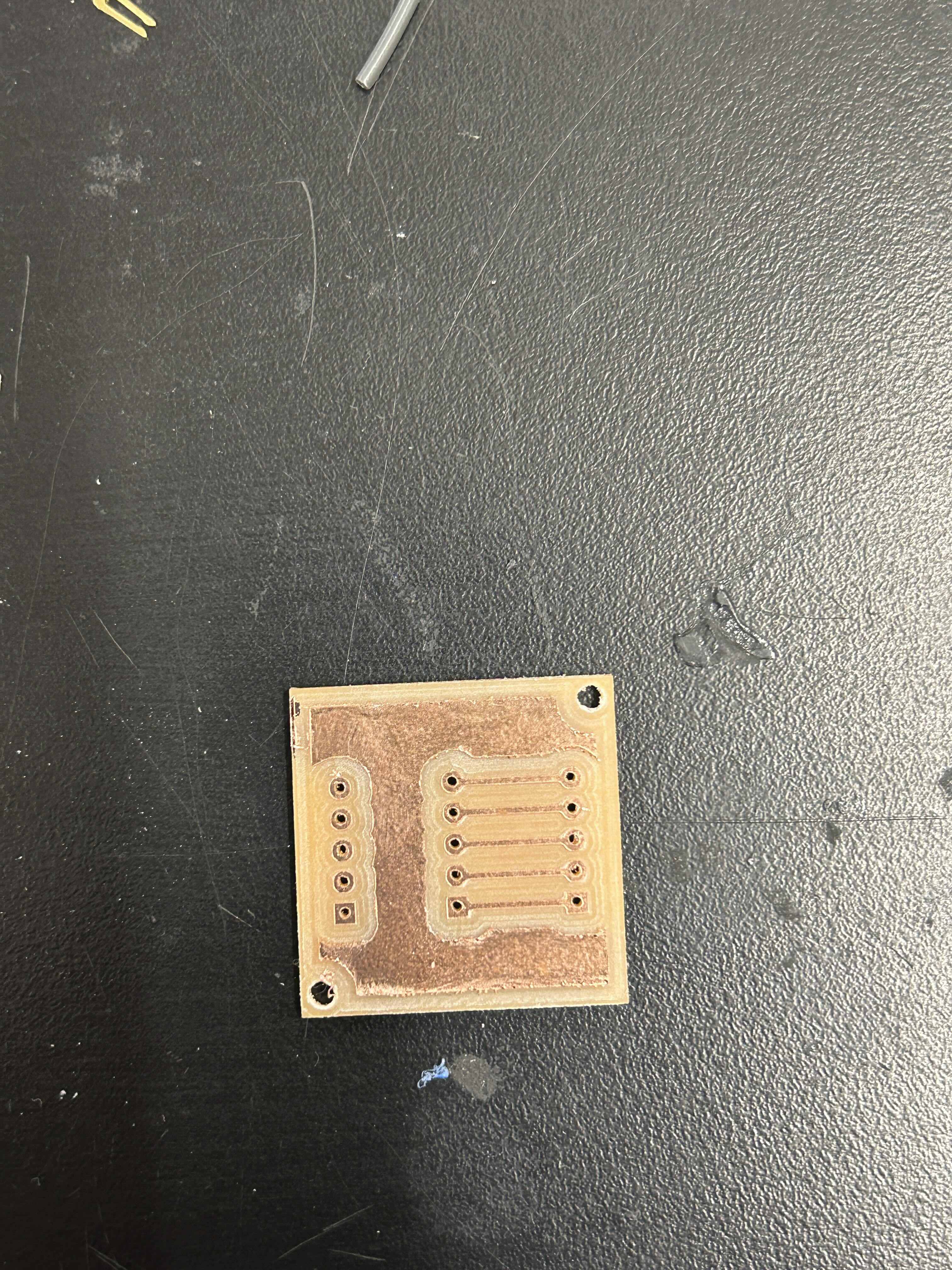
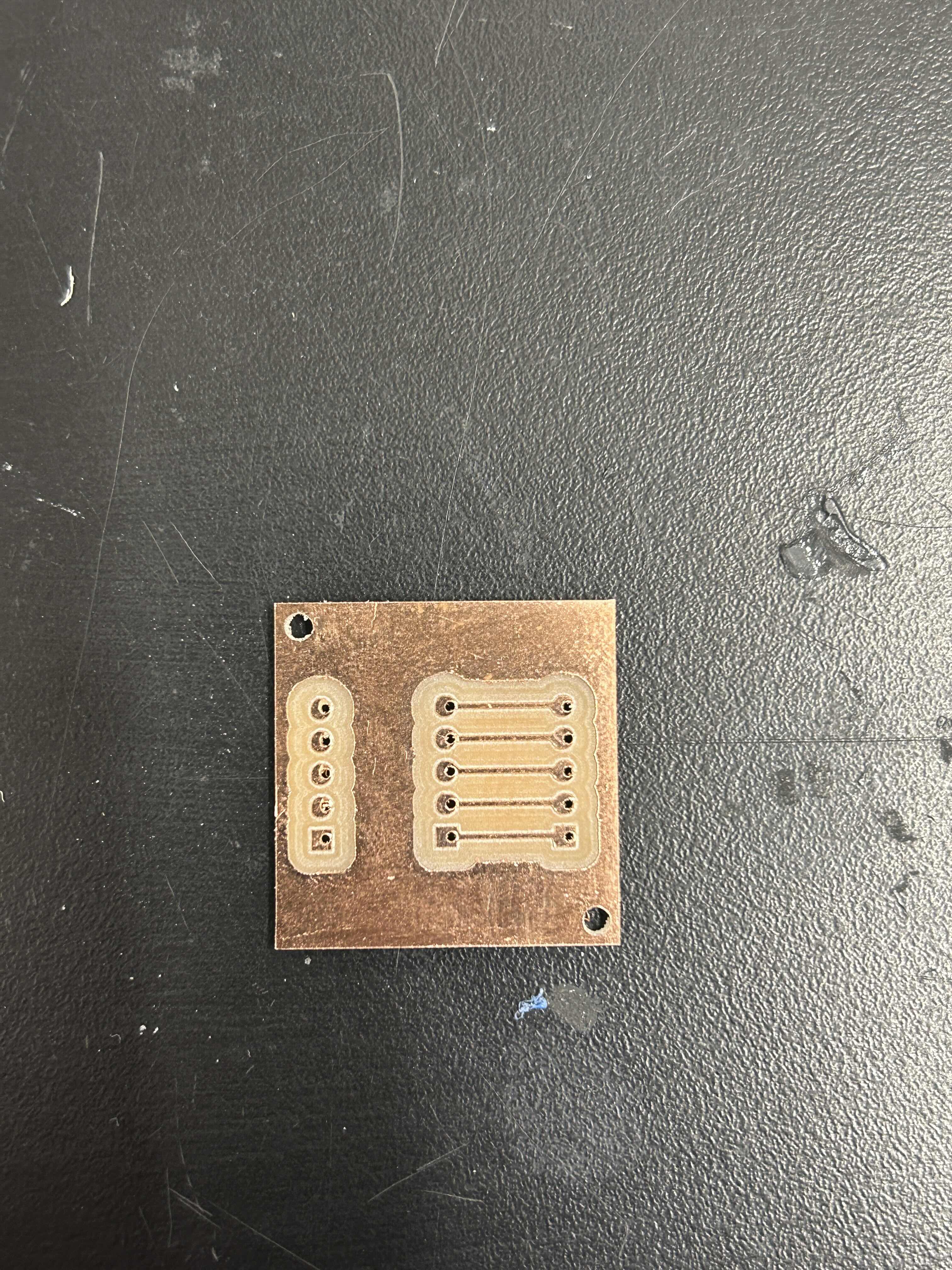
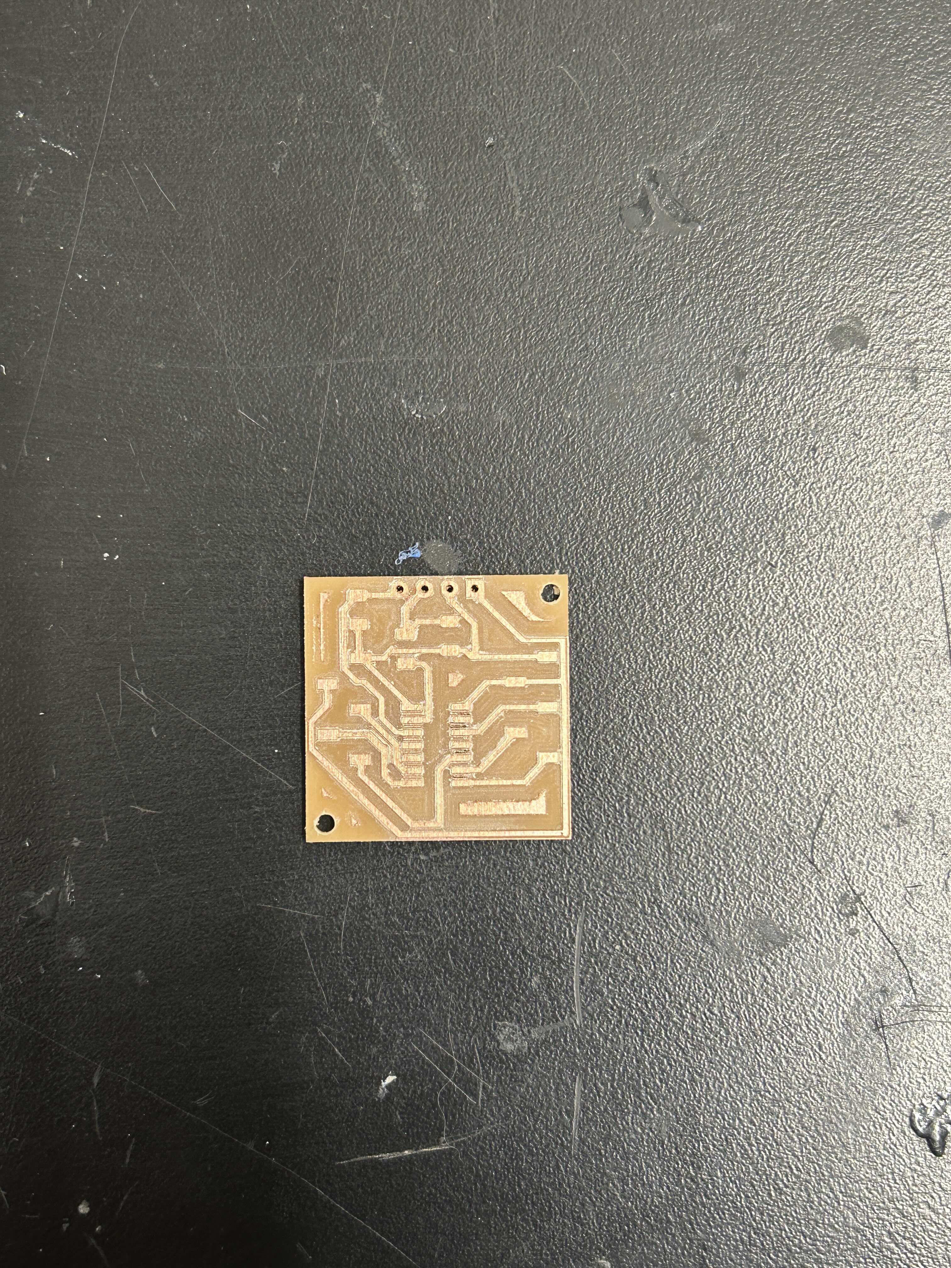
The milling process for the top board was simple, but making the bottom boards was not as easy. Basically I would mill the top side and then flip it over to mill the back. However because the pieces I was milling were so small I could only get one piece of double sided tape on them and only because of that the pcbs were not able to adhere well to the plate of the board and they would slide and sometimes just come right off the of the bed. Because of this I could only make two of these double sided boards because of time constraints
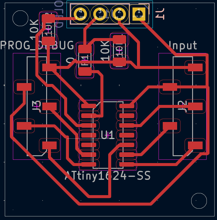
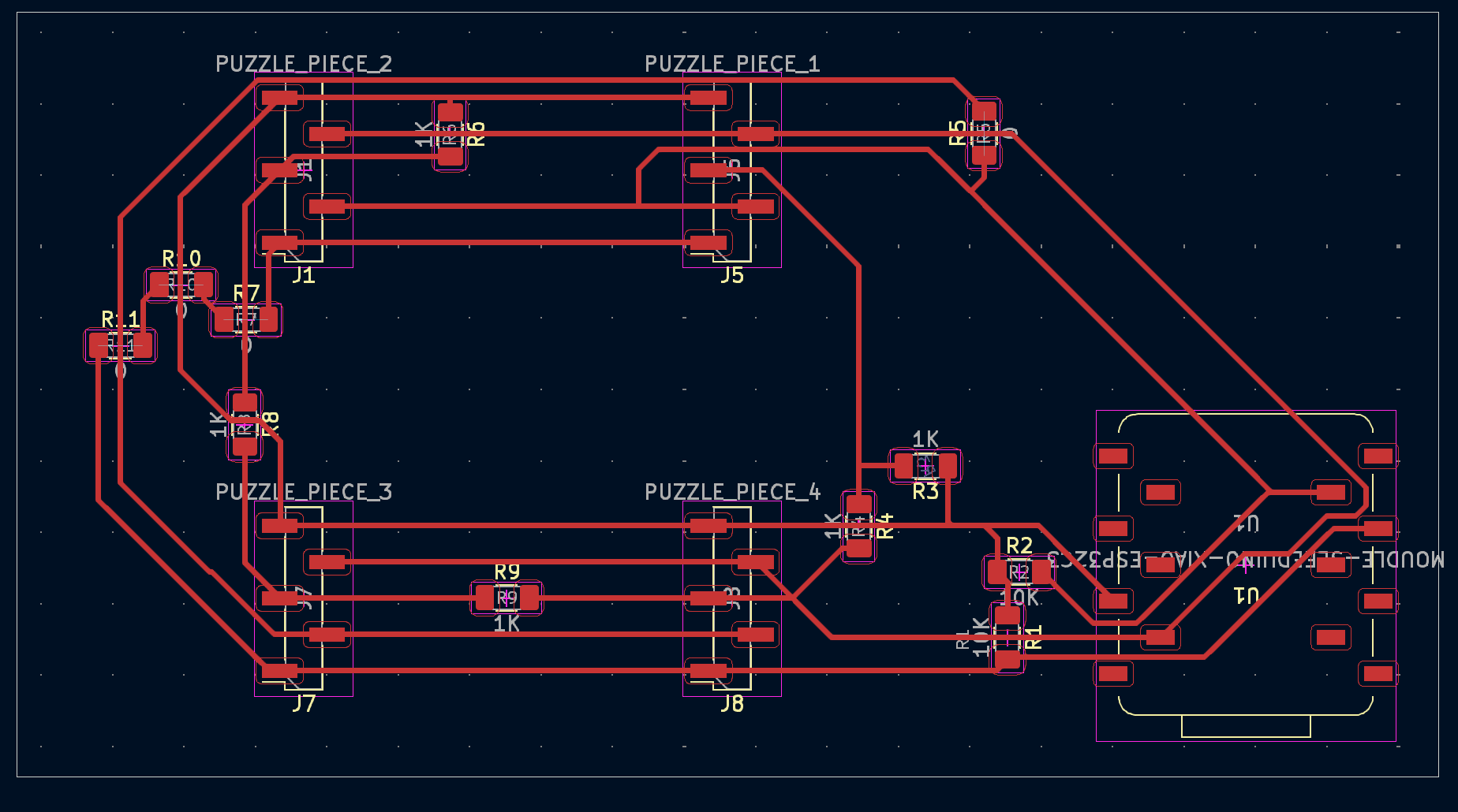
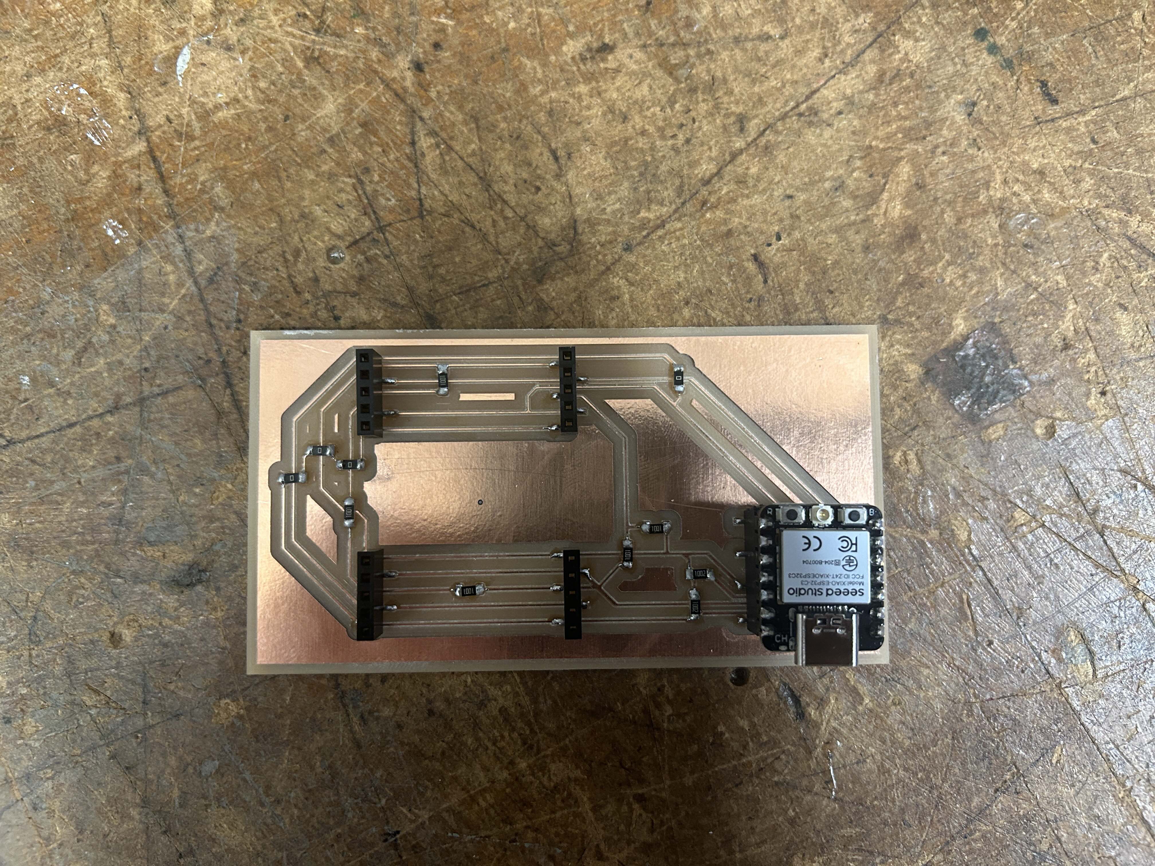
After making the pcbs for the puzzle it was time to make the pcb for the puzzle grid
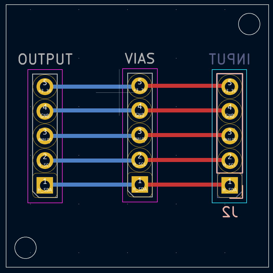
However, before soldering everything together I missed a shorted between the SDA and SCL lines of my board. I cut away from the SDA and SCL lines until their I saw that there was no continuity between those points on my board. However, when I would run an i2c scan test it would take multiple seconds to try and fail to send a message to a peripherial device, where normally if a device is not connected on the i2c line it will fail immediately. I have found this to be an issue with SDA and SCL being shorted together or have a lot of noise on the SDA line. However, I could not find SDA being shorted to any pin
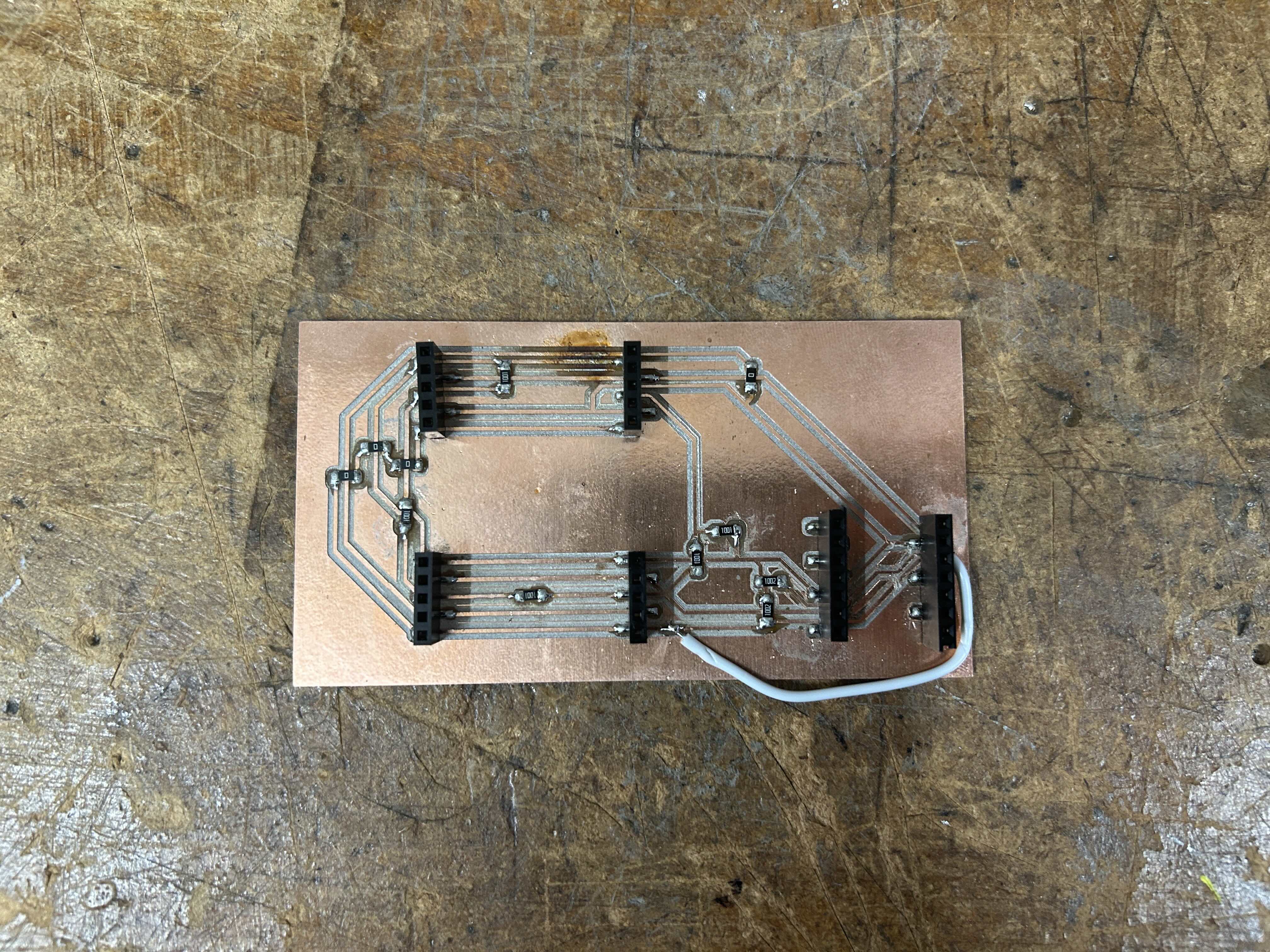
As a last ditch effort I tried cutting the SDA line and resoldered it later in my circuit, but I had a suspicion that the short with SDA was happening on a trace below the sockets that I had already soldered on the board. However, no luck and I simply just had to remill another board
After the boards were milled it was time to program everything. As a reminder of how this system works the pieces get randomly assigned pieces of a puzzle, the puzzle pieces know where they are in the grid because of a set of voltage dividers which put differnet voltages on different pins. The puzzles pieces communicate to a main controller their position and then when the puzzle is in the solved and then play a winning message on the screens
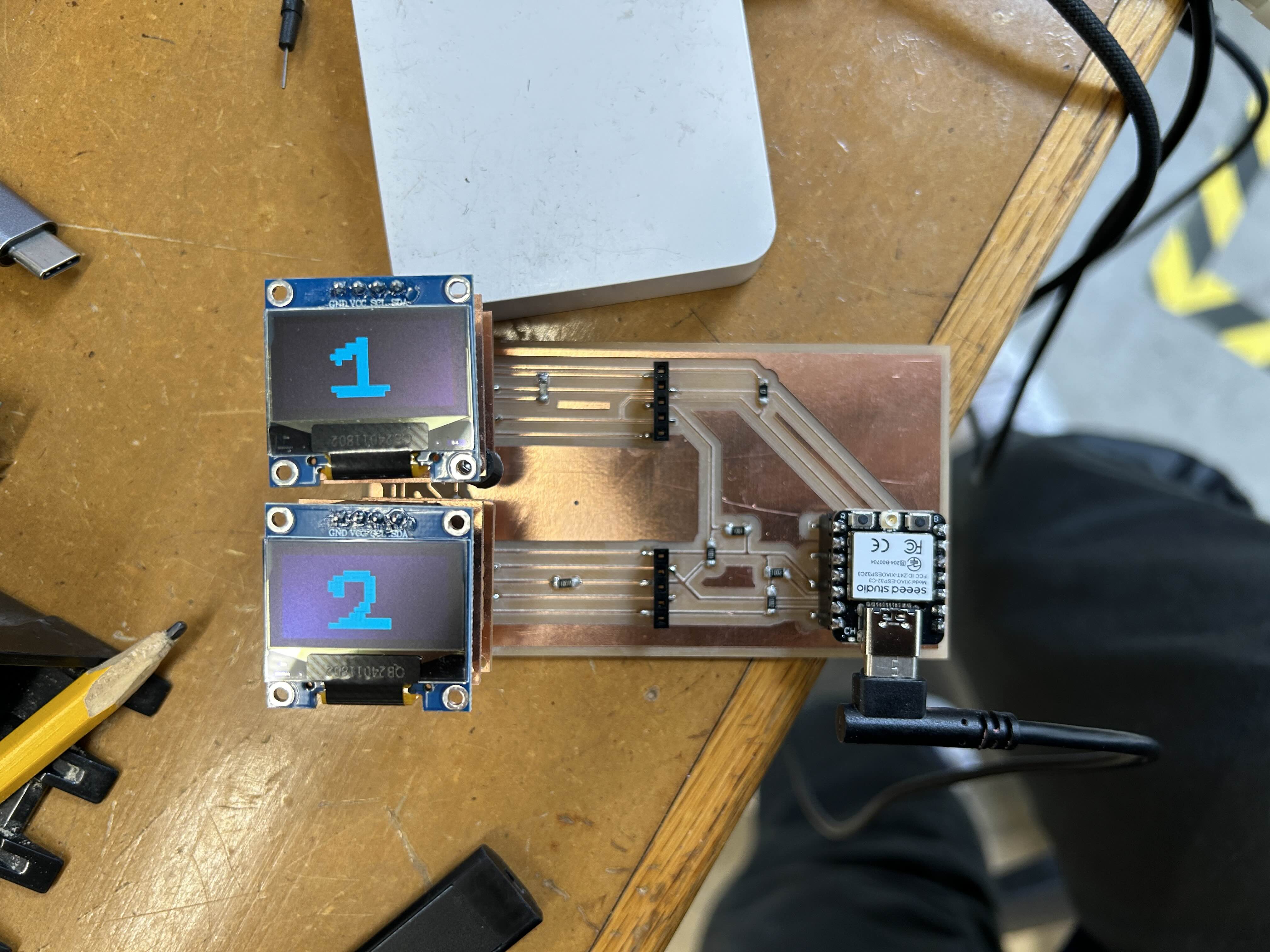
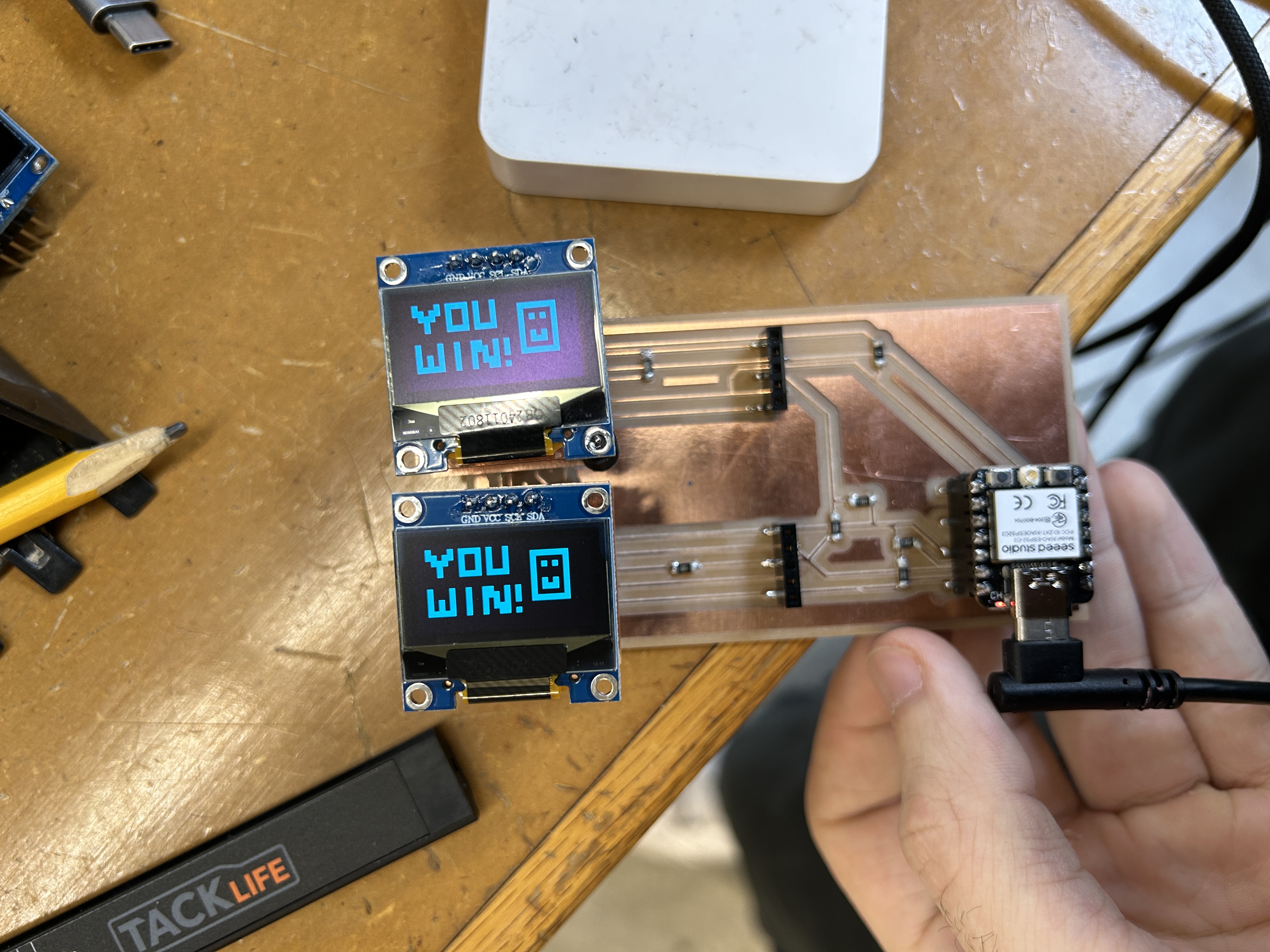
The code integration was actually very smooth. However, one thing that was surprising was how unreliable the connection between the puzzle pieces and the main controller even with the header and socket pins. This I think was caused by the amount of give that the pins and sockets had. Also the fact that the puzzle pieces had no support structure restricting its movement and stoppign the pieces to move around in the sockets.
Demo
Download Files
Issues that I faced
- Bad Set Screw in SRM (possibly stripped)
- Milling on a stock that was mostly cut out or small stock without sufficient tape
- There is more give in pin to socket connect than I would like
- My brain is stupid (That is more of a personal thing)
- There was short between the i2c lines on one of my original boards. I carved away the extra copper and the multimeter did not read continuity between the two lines but I still had the same issue and when I milled a new board the problem disappeared
- I was getting issues sending a lot of data over multiple transmissions over i2c