Week 2: Vinyl Cut + Parametric Lasercut
xdd44, Sep. 18, 2024
Lasercut Test (Group work with Zhi Ray Wang)
We used 1/8" acrylic sheet for this assignment, cut at Building 3 Arch shop's 75W Epilog lasercutter.
The lasercutter supports setting of power, speed, and frequency. The suggested setting of our material from Arch shop is 20 speed, 60 power, 5000 frequency. Therefore, we applied the 20 speed and 5000 frequency, and varied the power value to find the actual suitable setting.
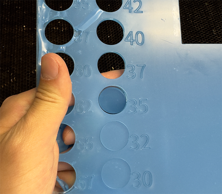
We used color mapping to cut circles with different power at once. In the first round, we varied the power from 50 to 70, and all cut through. Therefore, we performed the second round with power from 47 down to 25.

The second test round: a gradient of blue to map 25 - 47 power to circles, and red to score the annotations.
We found out the circle is barely detachable at power = 35, while it didn't cut through at power <= 32. Therefore, 35 - 40 is pretty much enough power.

Power test result
Next, we designed a simple joint to test the kerf clearance. We offset the joint cutting lines from -0.020 inches to +0.015 inches.

Clearance test cutting lines. Blue denotes cutting line, black denotes original lines, and red is annotation scoring.
We cut them out and tried to join them. The joints with -0.020 to 0.000 offsets turned out to be loose. The pair with +0.005 offset provided comfortable friction. The pair with +0.010 offset cannot be joined with bare hand, but I hammered them together. The pair with +0.015 offset cannot be joined at all. Therefore, the kerf is about 0.005 inches thick.

Testing joints joined together.
Vinyl Cut
I converted my logo + nickname to a sticker.
The cut doesn't match the toolpath. My understanding is the vinyl roll was too wide and the two pinch-rollers at the side were not rotating exactly the same amount. So the vinyl was tilted when loading.

(From top to bottom) Original Logo; Generated Toolpath; Cut; Weeded Sticker; Transferring Sticker; Sticker on Laptop
Lasercut - Generic Assembly Kit
I would like to keep things simple, so I designed a generic assembly kit consists of only polygon-shaped main pieces and capsule-shaped connecting pieces.
For polygon, I put slots at midpoints of each edge. I defined several variables:
-
Inner RadiusDistance from polygon center to its edge.-
Slot DepthLength of the slot.-
Side CountNumber of sides of the polygon (>=3).-
Fillet RadiusRadius of fillet of polygon corners.-
ClearanceClearance for kerf.
The cutting lines of the polygon can be constructed by mirroring/rotating the segment shown below:

Parametrized individual segment.
And I used Grasshopper to construct the cutting line.

Grasshopper script for individual segment.

The script for mirroring/rotating to get the entire polygon.
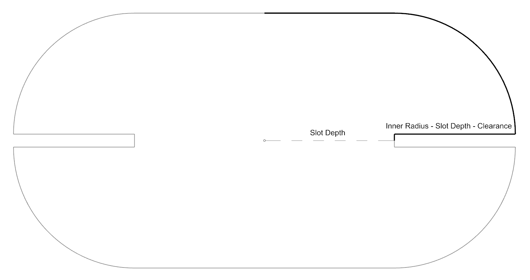
The connecting piece is in capsule shape, with slots at both side.
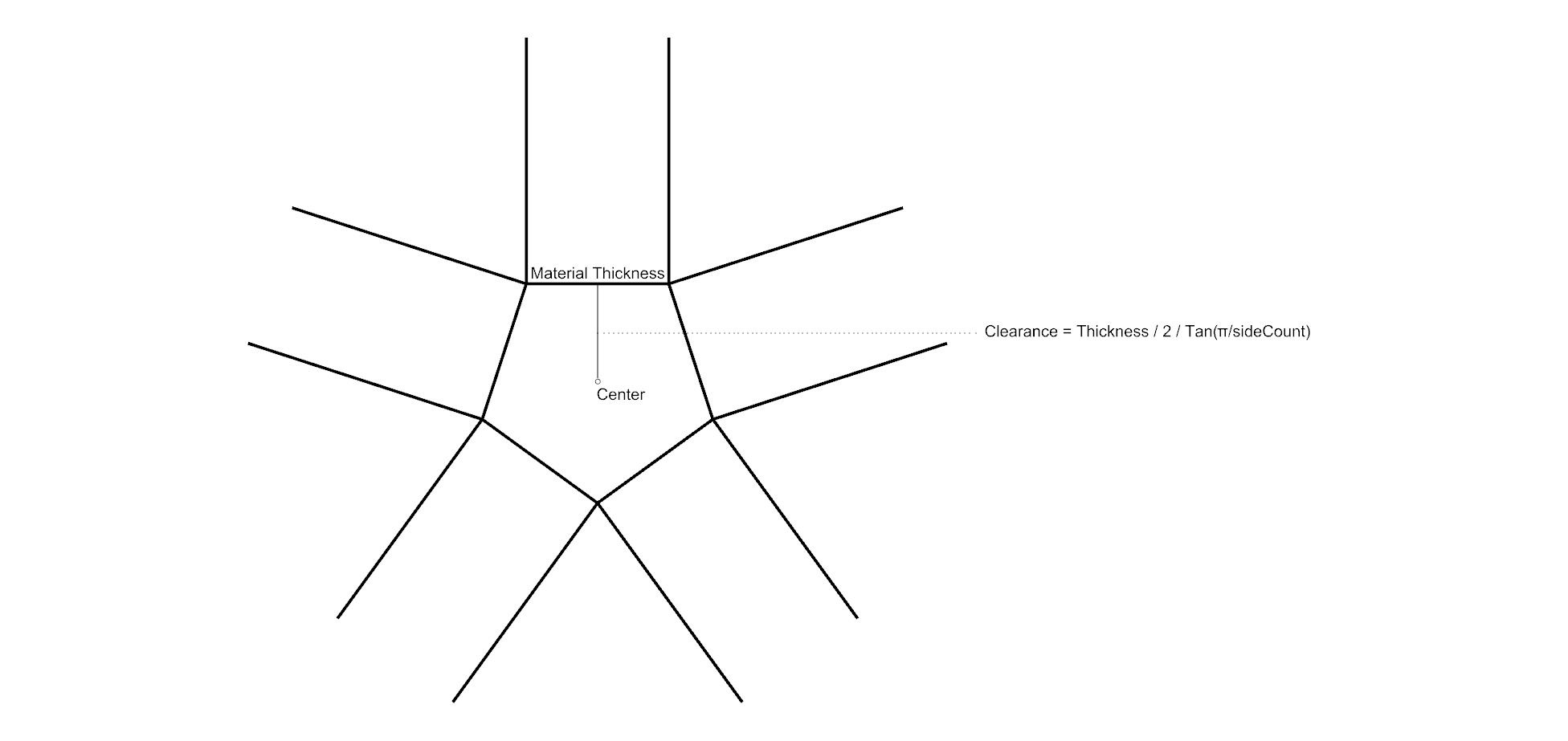
A special thing to notice is that when the connecting pieces meet at the center of the main piece, a clearance should be considered due to material thickness.

Diagram showing clearance consideration at meeting place of 5 connecting pieces.

Cutting line of connecting piece, by mirroring the segment twice.

The script for the steps above.
With scripts ready, I can now produce various kinds of main pieces...

Variants with different side counts, slot depths, and fillet radiuses.
...and plan my assembly virtually.

Assembled "xdd" with triangle main pieces.