Week 5: Electronics Design
xdd44, Oct. 5, 2024
Observe the Operation of a Board (Group work with Zhi Ray Wang)
We used oscilioscope at N51's MAD studio to test the electric signals in my LED matrix. The matrix uses MAX7291 chip driver, and has 5 pins: VCC, GND, Data in, Chip Select, Clock. I kept my 2048 game's matrix layout, and used one extra wire to retrieve the signal from end pins.
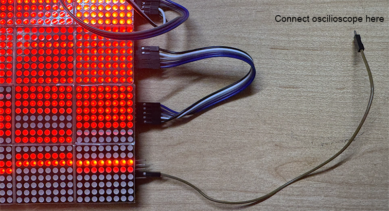
Retrieving wire
First, I write code to set all LED on every frame and test Data In pin, which showed a low/high signal. The cycle length is around 35 - 40 μs, which indicates the data update frequency is around 25 - 30 kHz. However, it is unsure what this cycle does, since to update the whole board of LED, 16 * 8 * 2 data will be sent (16 matrices, 8 bytes address + 8 bytes data for each board).
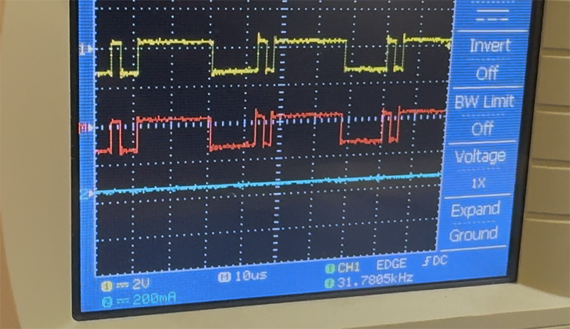
Signal from Data In pin
Meawhile, the clock pin showed a cycle of 2μs, which suggest a clock frequency of 50kHz.
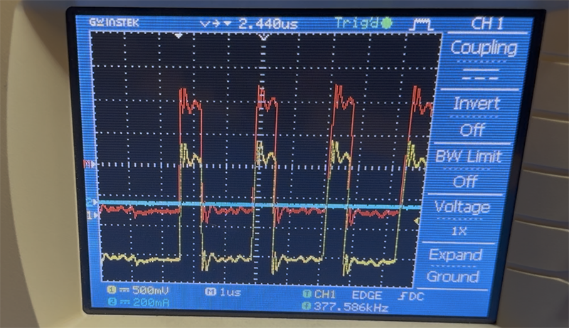
Signal from Clock pin
The Chip Select pin showed a cycle of 625μs, suggesting a data reading frequency of 1600Hz.
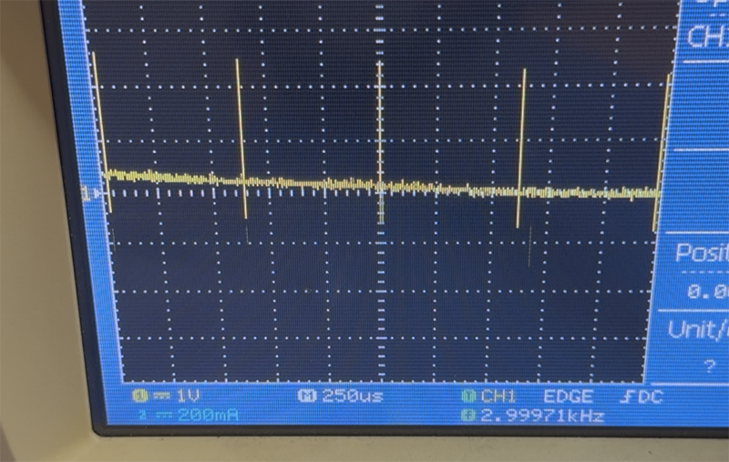
Signal from Chip Select pin
The Chip Select signal cycle should directly reflects how frequent LED data updates. Therefore, I modified the code to update LED once every second. Indeed, Chip Select pin showed an 1Hz signal.
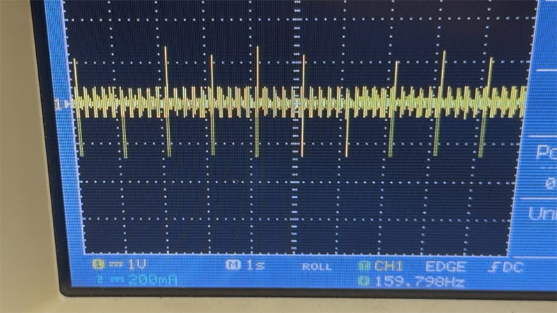
Signal from Chip Select pin after modification
What we did not understand at all was both VCC and GND pins showed a wave of nearly 1V at 60Hz. We connected VCC to Arduino board's 5V out, and the board is powered by my MacBook without external power, which means we shouldn't get alternating current.
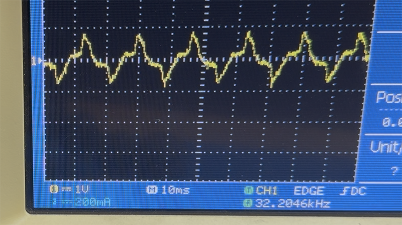
Signal from VCC and GND pin
Design a Development Board
My idea is to design a board that 1) integrates an RGB sensor; 2) controls my previous MAX7291 LED Matrix or similar drivers. I decided to use a XIAO ESP32-C3 chip and referred to Adrian's works in order to understand pins and basic components including on-board button and LED.

Schematic Diagram of My PCB
Most of the design is simple once I understand which pin goes where. One thing I'm particularly confused about is the connection of APDS-9960 the RGB sensor. It is at a smaller scale than components that Adrian used. Also, KiCAD does not allow me to connect to the pins.
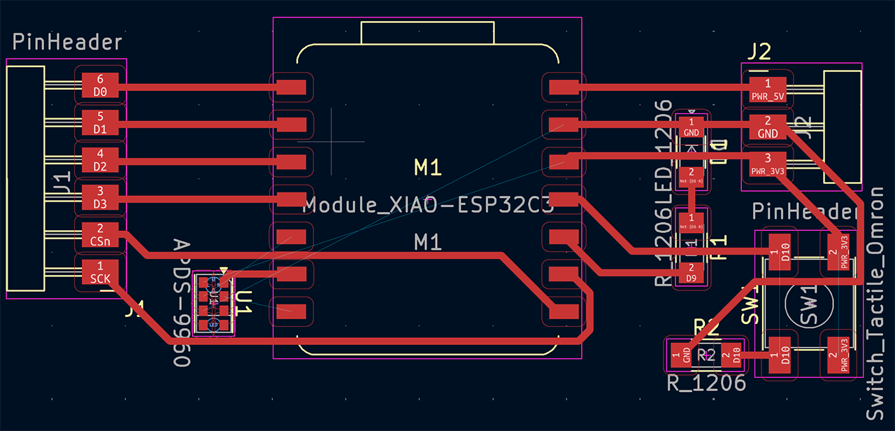
Actual Trace of My PCB
Anthony kindly pointed out that I could use an easier sensor with 4 pins from inventory, and use 0 ohm resistor for trace crossing. Therefore I revised my design.
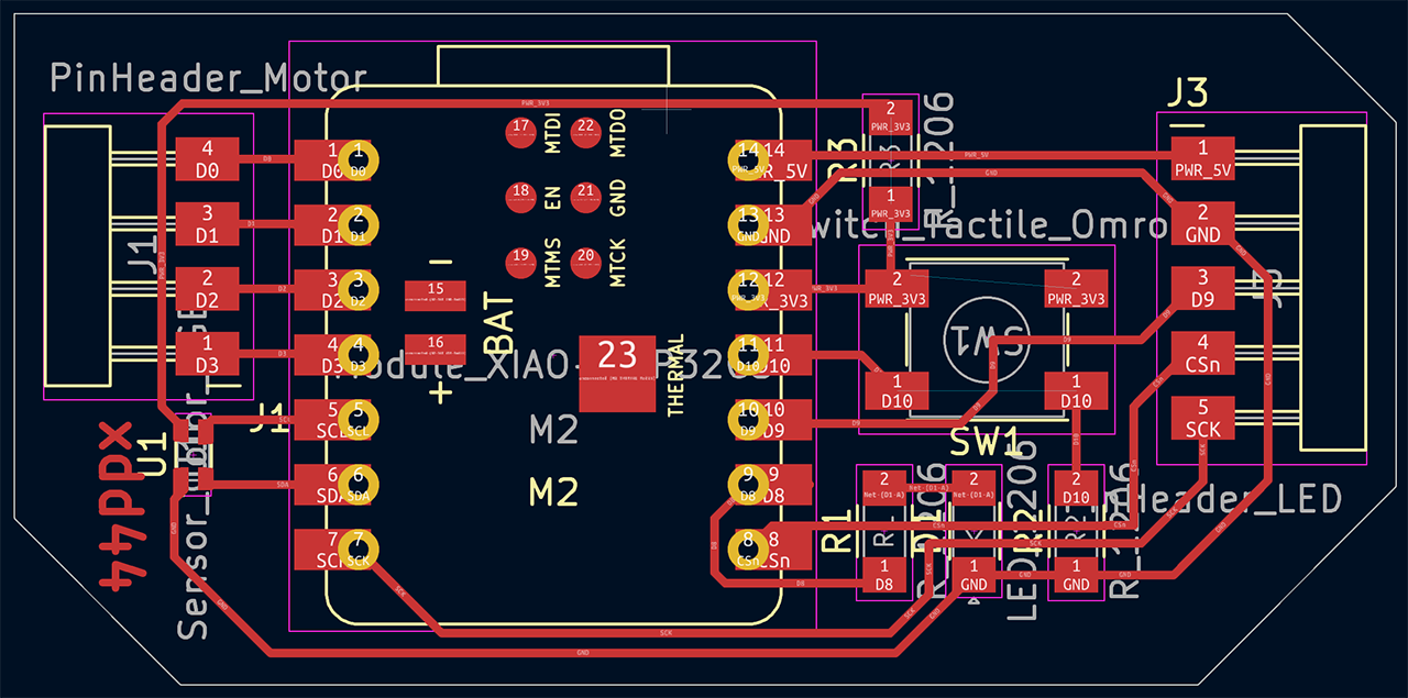
Second Design My PCB