Final Project
Building Process
Materials and Components
I ordered the following components from Amazon:
- Large OLED screen (here) - $14.88
- Buttons (here) - $7.99 for 10
- Speaker (here) - $11.18 for 4
- On/Off switch (here) - $6.99 for 5
- Battery pack (here) - $6.99 for 8
- Force Sensitive Resistor (here) - $8.98
I also used the following components, which I got myself or from inventory:
- Raspberry Pi Pico W - $6.00
- Adafruit SPW 2430 Microphone - $4.95
- Adafruit MAX98306 Amplifier - $8.95
- Resistors - 0, 10k
- Birch plywood - 1/4" & 1/8"
- Clear resin (Formlabs resin printer)
Breadboarding
I started off breadboarding all the smaller component systems, to ensure that my wiring was correct and the components were all functional (since some of them were dubious Amazon purchases with questionable reviews).
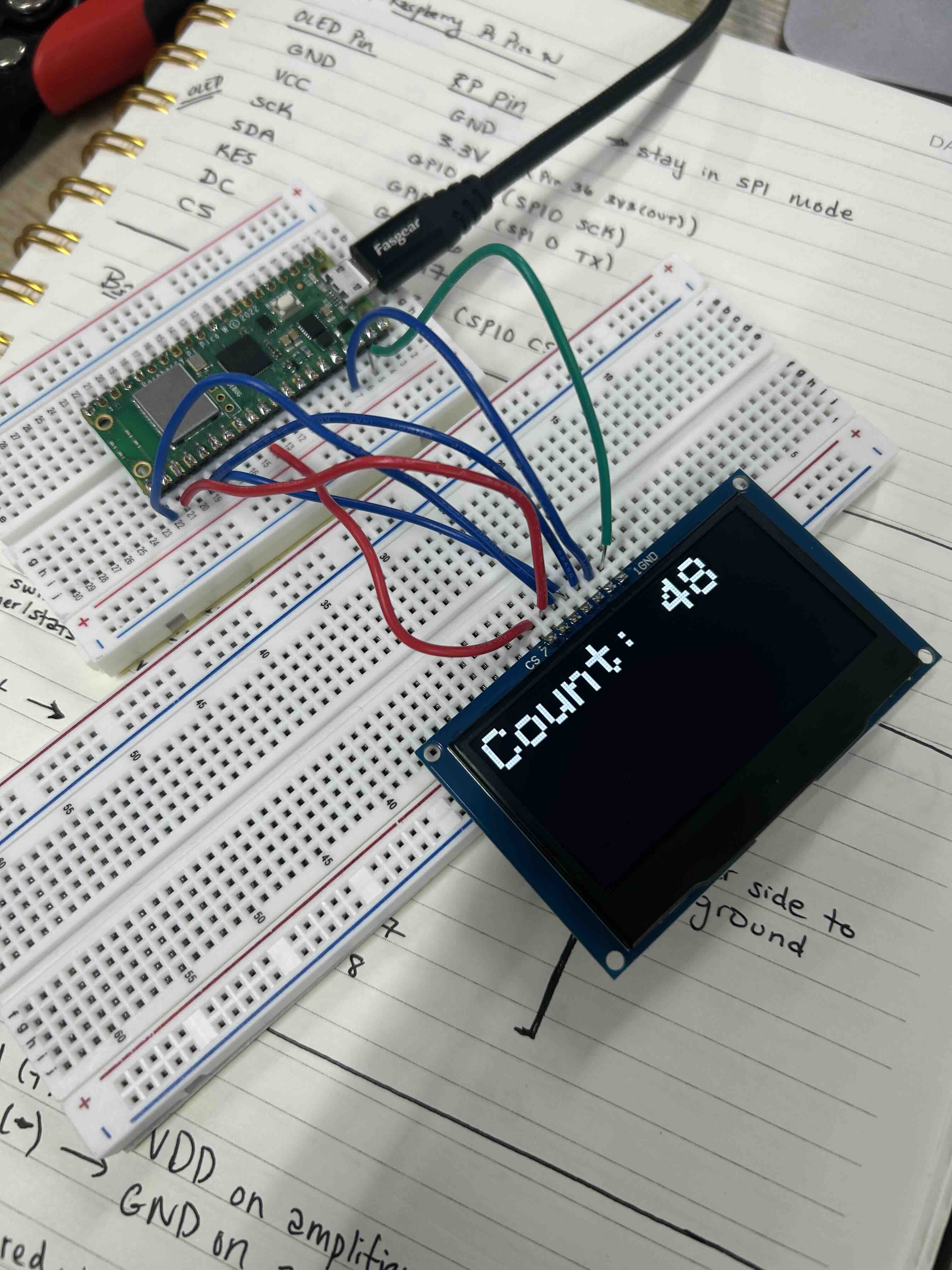
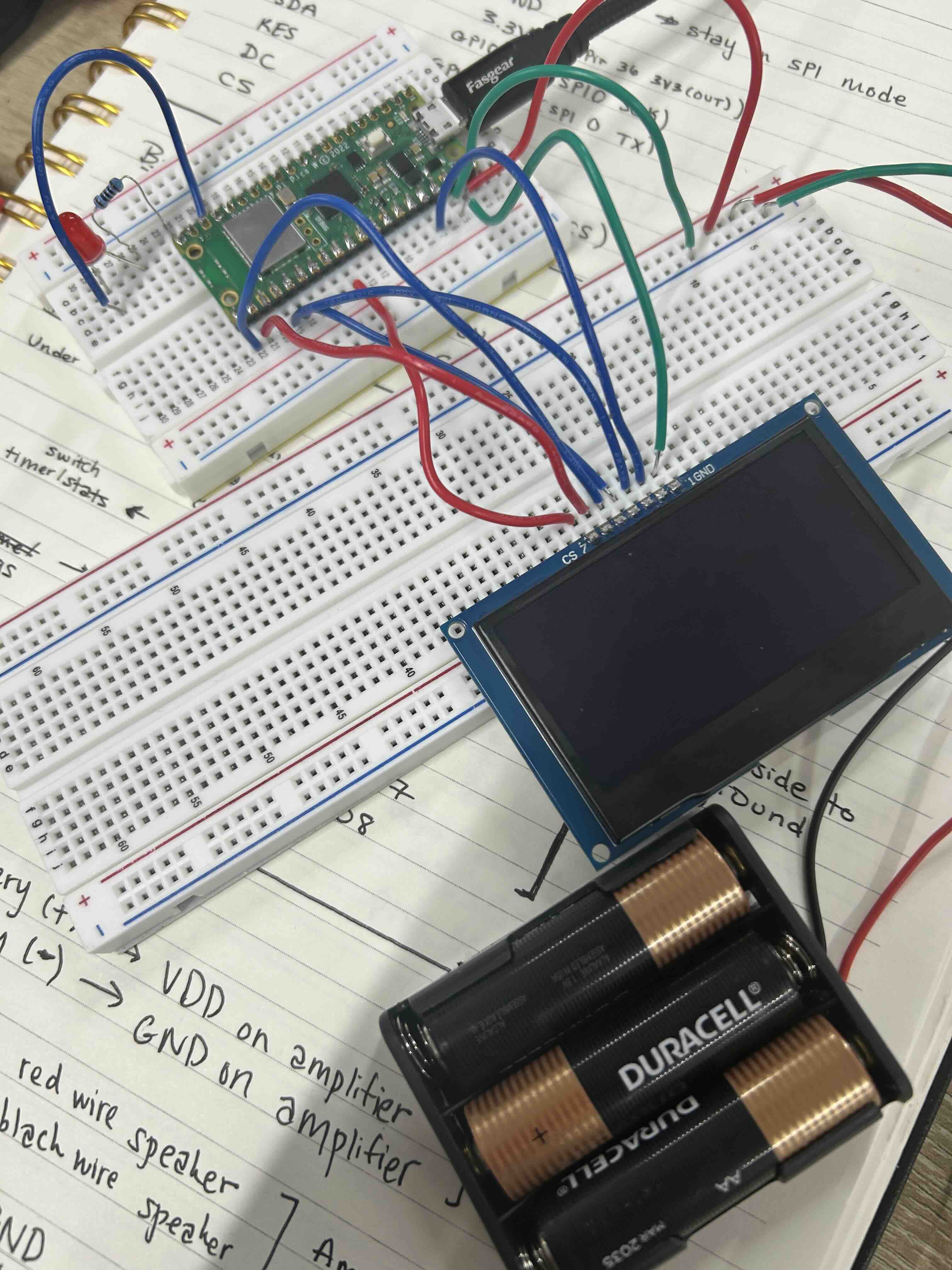
I started off with the OLED screen, having it run a simple program to count up from 0. I then modified the circuit to add a battery pack, so it could be powered independently of my computer. It took a rather embarrassing amount of time to get that working, as initially the OLED simply didn't turn on when I plugged in the battery. I checked the voltage going to all the pins and it was getting the correct amount of power, but for some reason the display wouldn't turn on. After trying to debug the hardware forever, I realized it could be a software issue... and quickly found a "while (!Serial) {;" that was waiting for a Serial Monitor to open... on my computer. Deleting that fixed the issue and got the OLED up and running on battery power. I then added an on/off switch and things went much quicker from there.
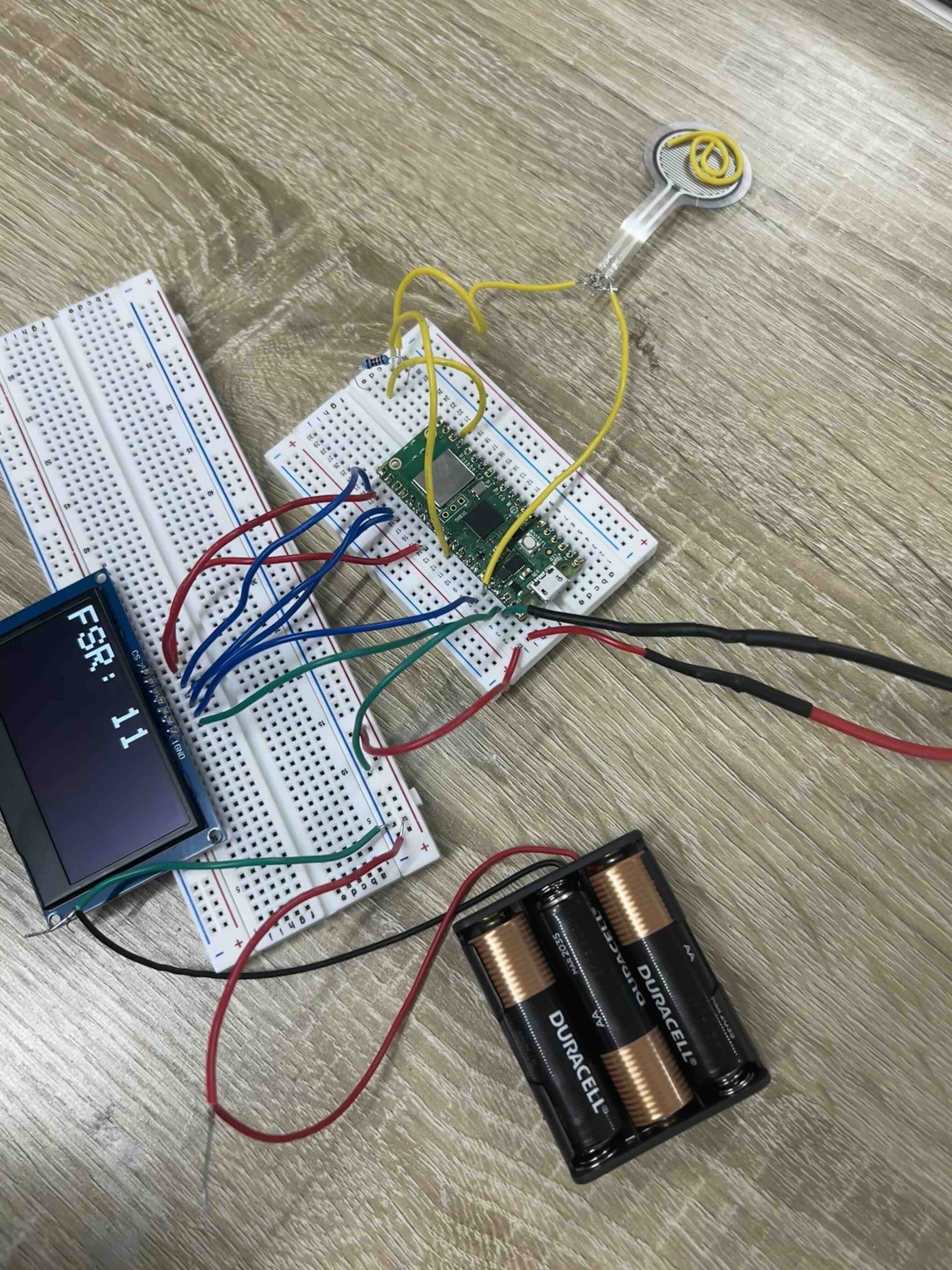
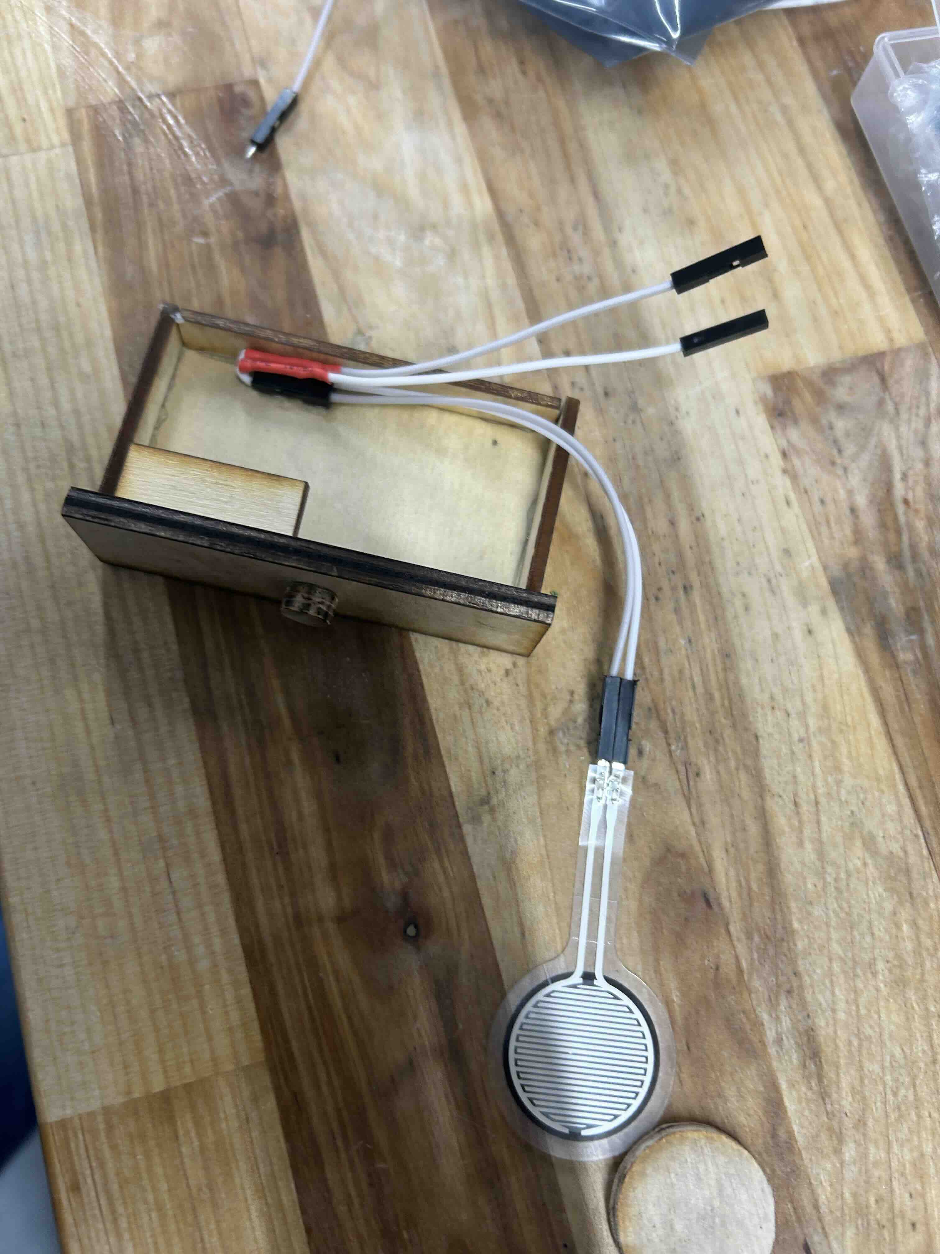
After that, I tested the remaining systems: rigging up the force sensor, the speaker, and the microphone:
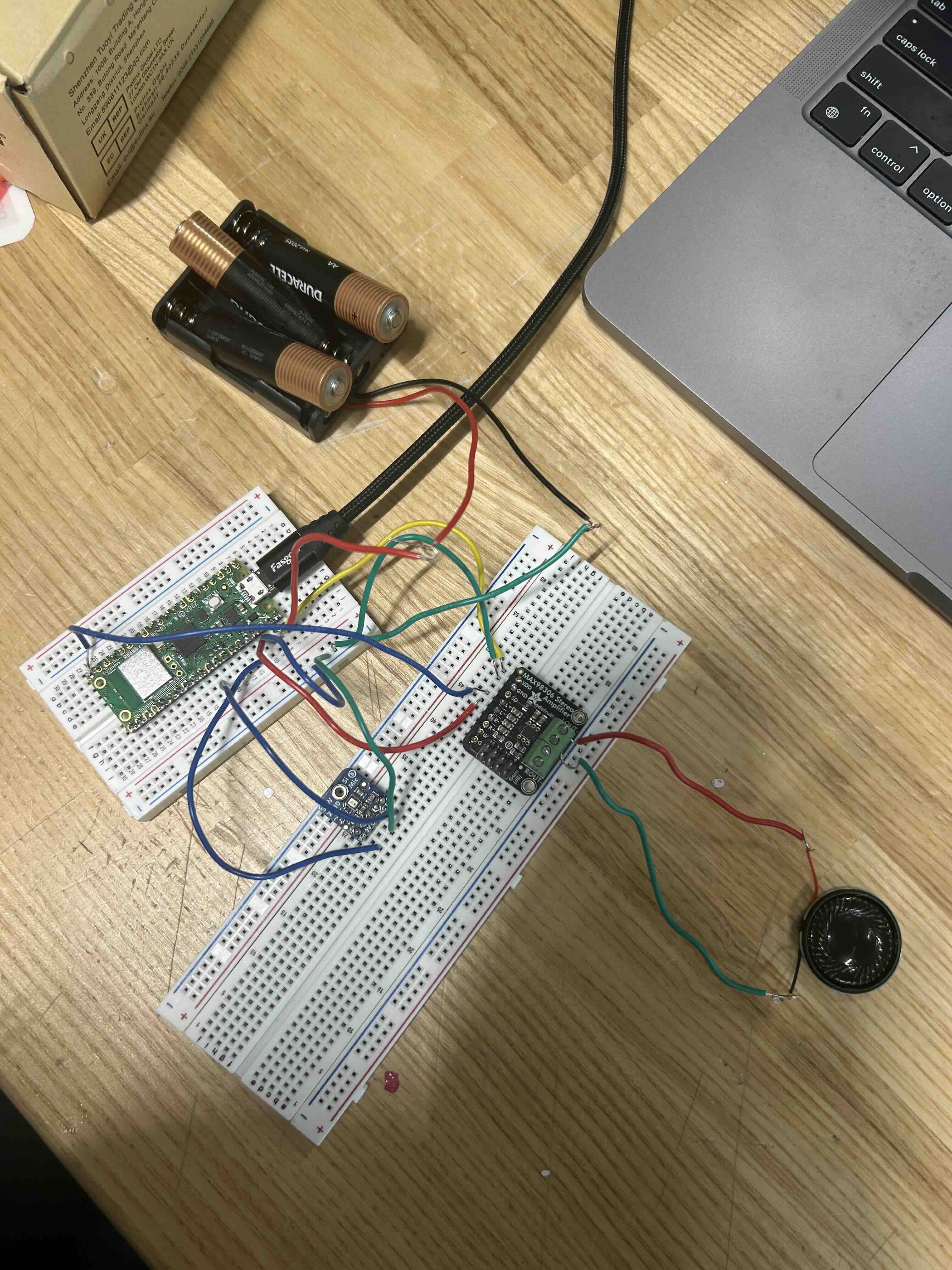
I was able to read out signal from the microphone, but was having some trouble getting it to work with the speaker the way I wanted to from a software perspective. I shelved this problem to come back to if time allowed at the end, since the basic system would work without it.
PCB Design and Fabrication
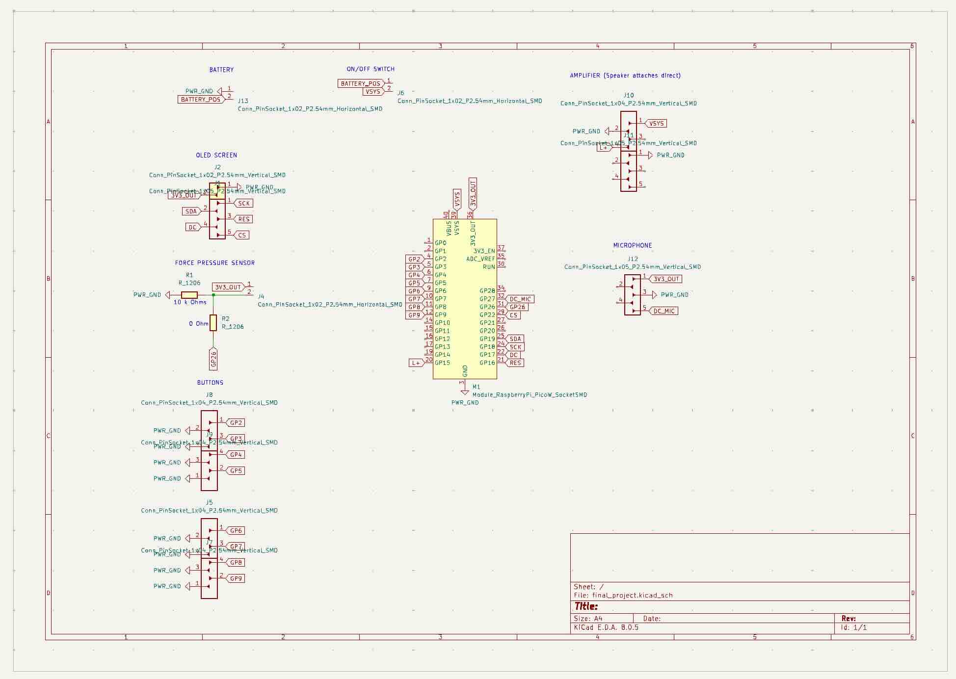
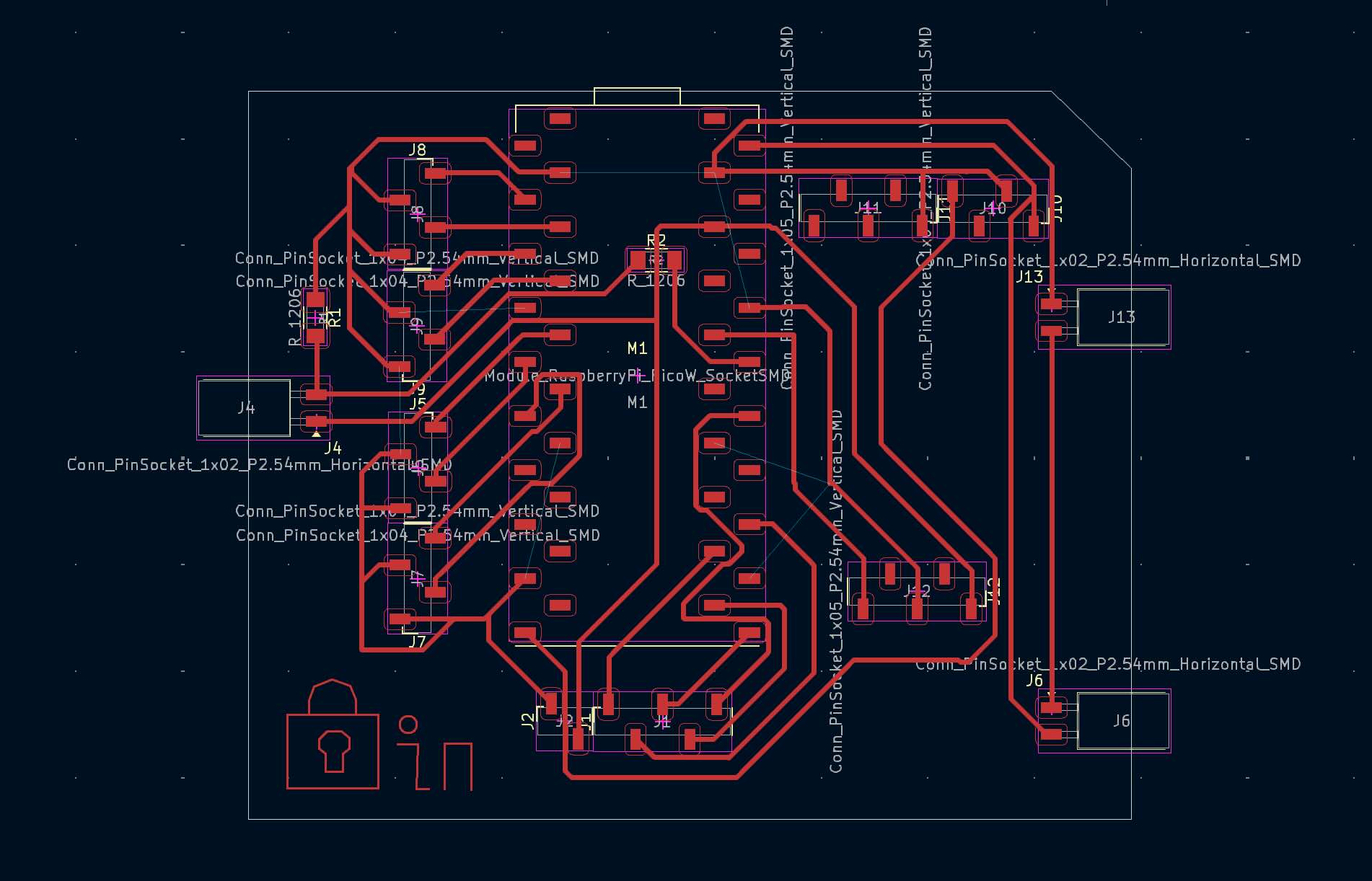
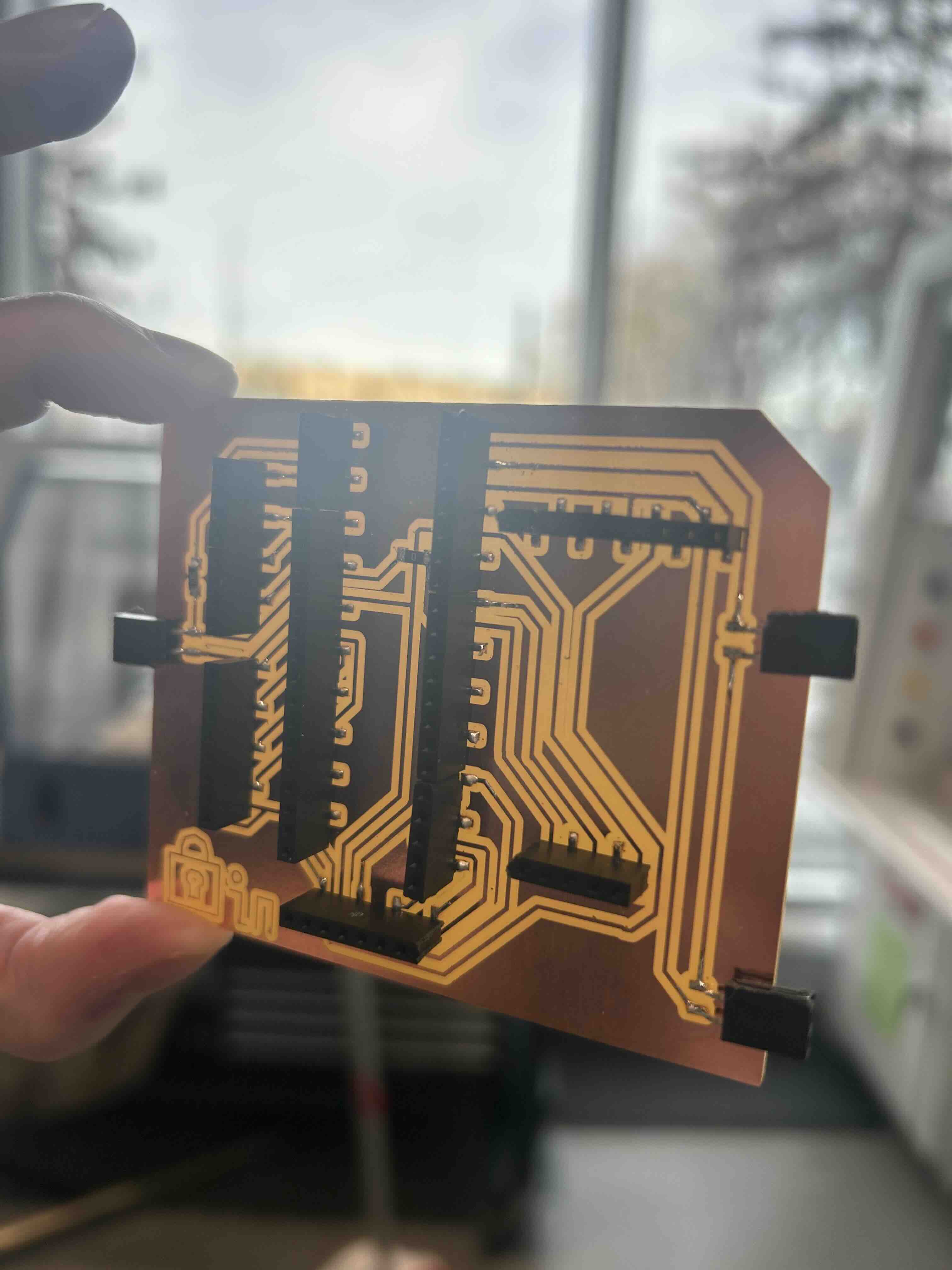
Based on the wiring from the breadboarding, I then designed my PCB in KiCad, where most of the actual components were just headers to connect to non-surface mount components:
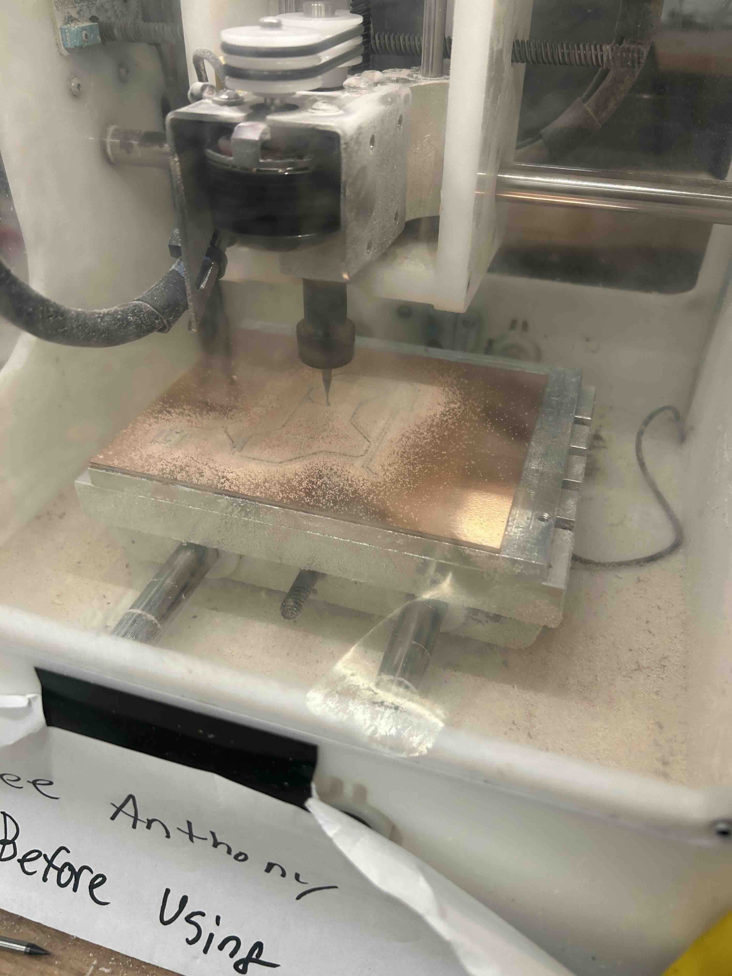
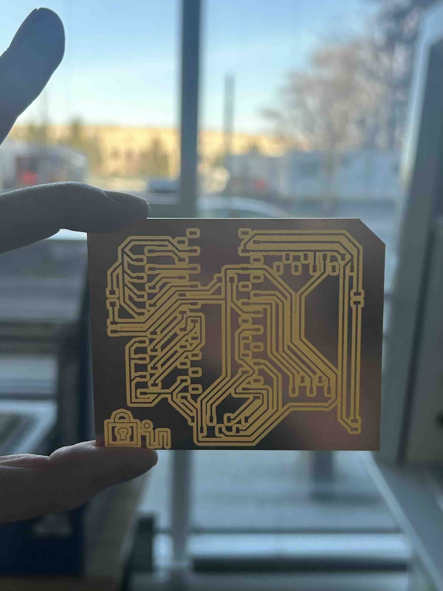
I had some issues milling with the Roland machine in the Harvard lab, where I kept getting portions of the board simply not fully milling. This is probably due to all the 1/64" endmills being broken, and the sacrificial layer not being fully level and flat:
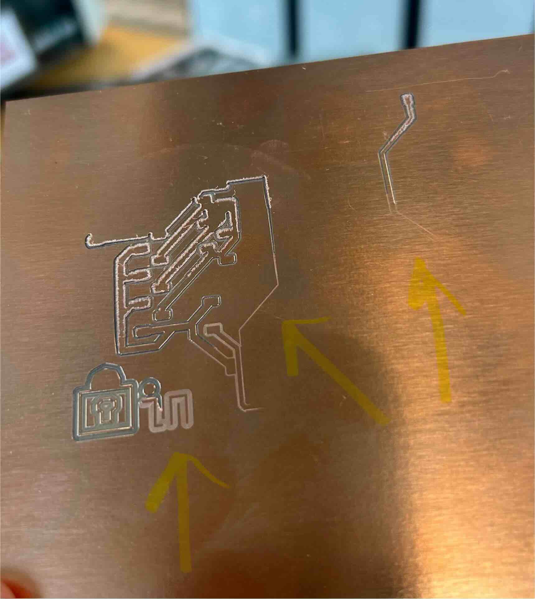
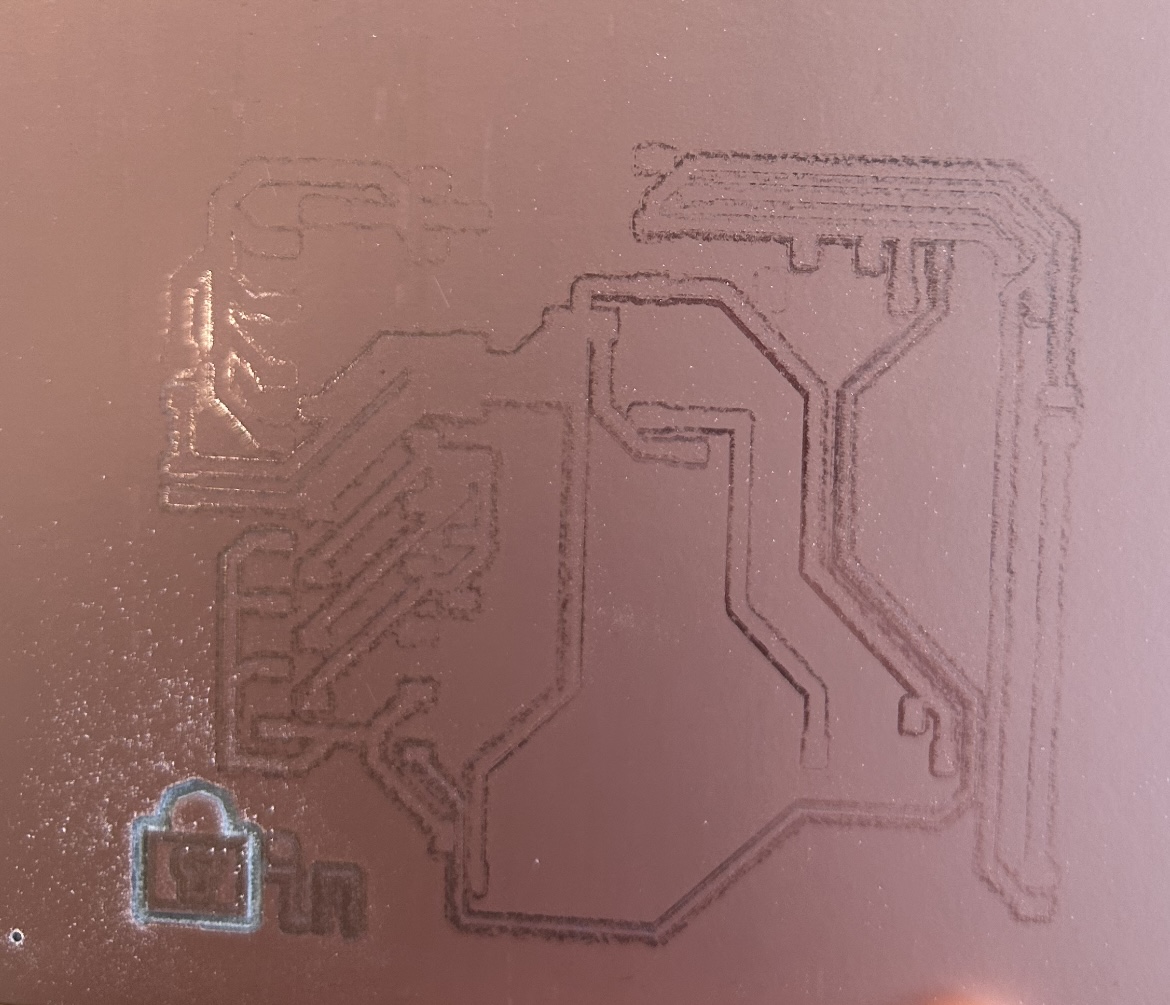
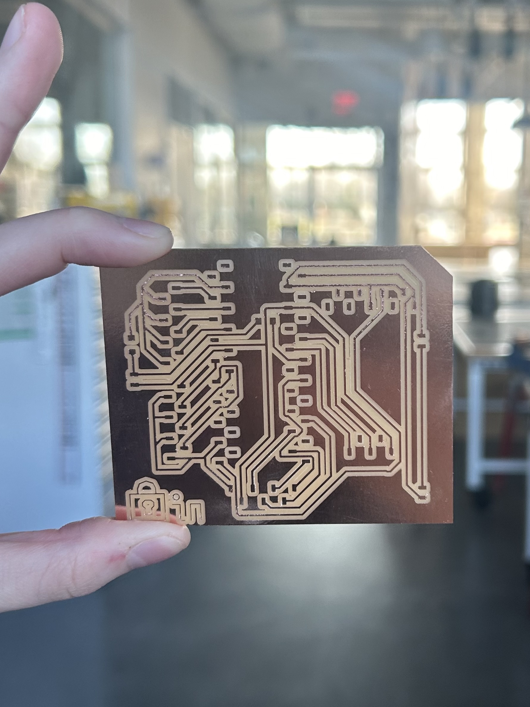
With time ticking, I eventually decided to go use the mill at one of the MIT shops, and things went smoothly from there:
Soldering
Next it was time to solder everything onto the board. Most of the soldering was just putting on headers, with the exception of a few surface mounted resistors. After doing quite a bit of surgery to break some female headers into the right size, I had the finished board:
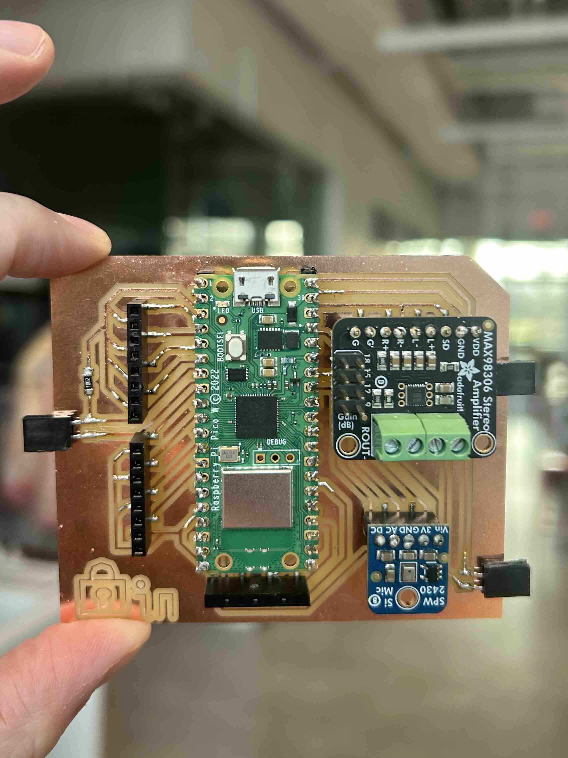
I then realized that having the headers sticking off the sides was not in fact a brilliant design choice, after promptly snapping one off and nearly breaking my PCB. Those all got cacooned in hot glue immediately after to prevent further damage. However, having them sticking off also took up unneccessary space, which made things harder when trying to fit everything into the box later on.
Box Design
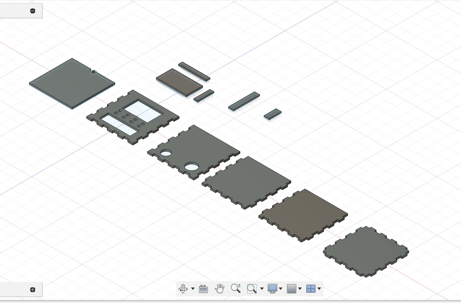
I used Fusion 360 to design the box:
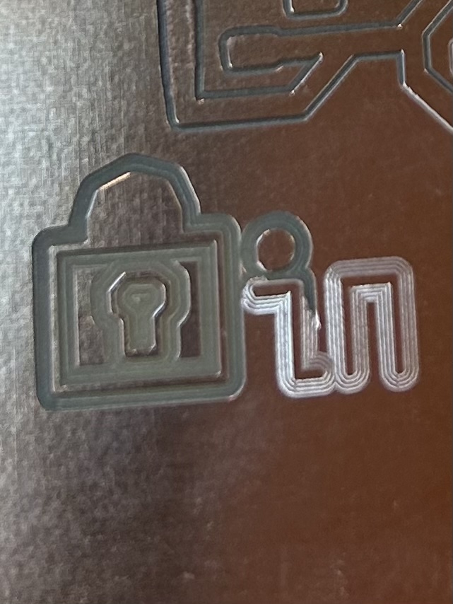
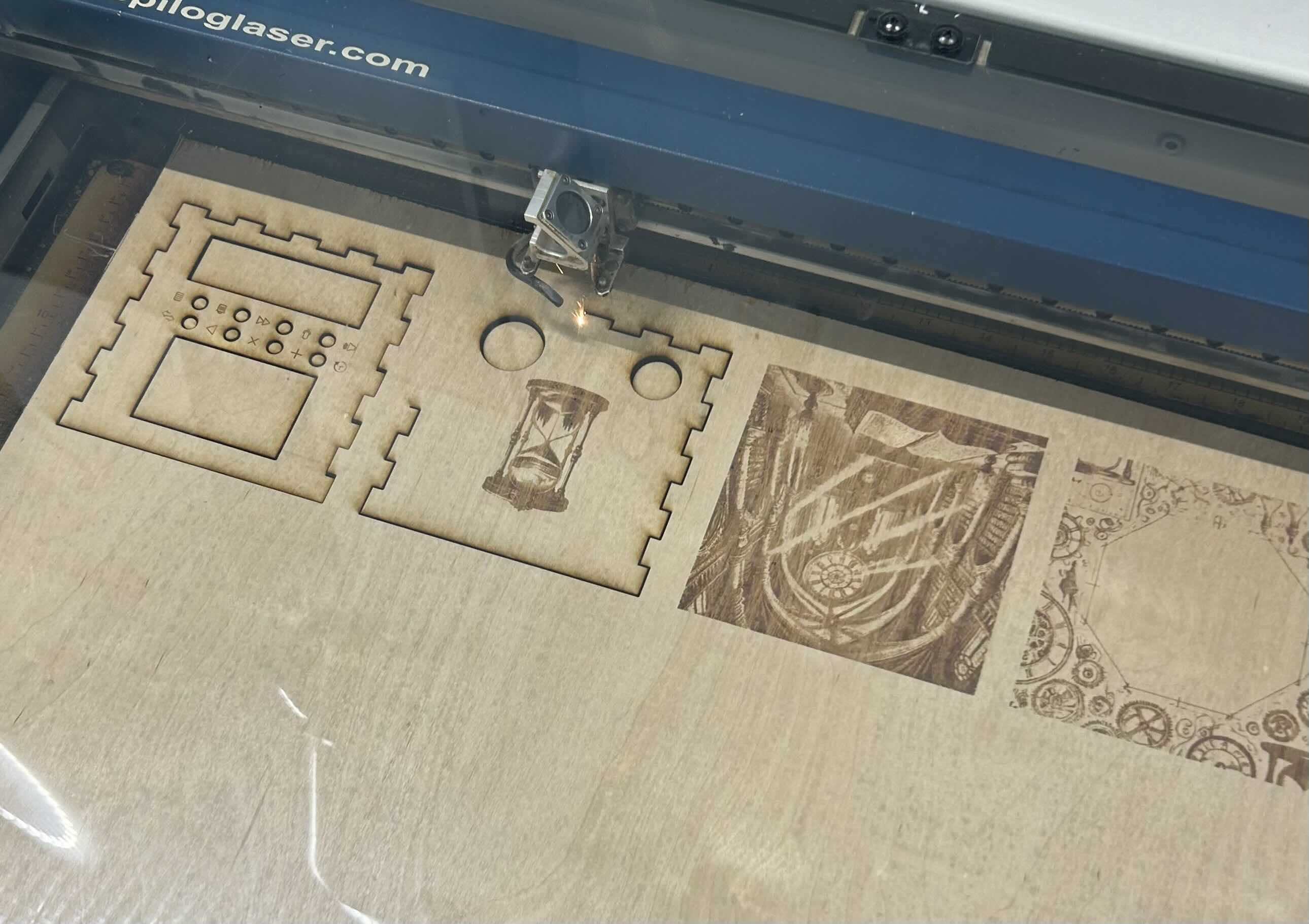
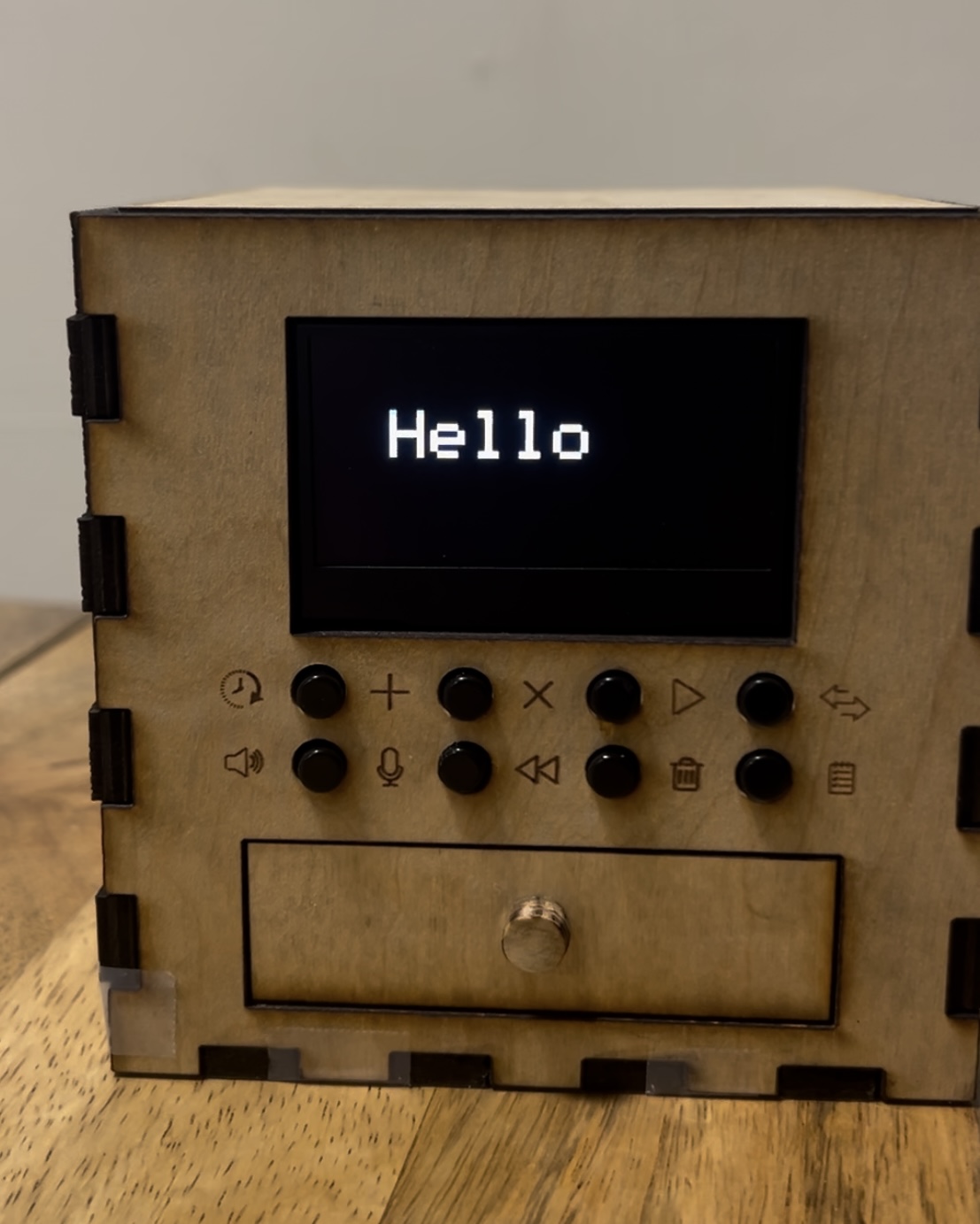
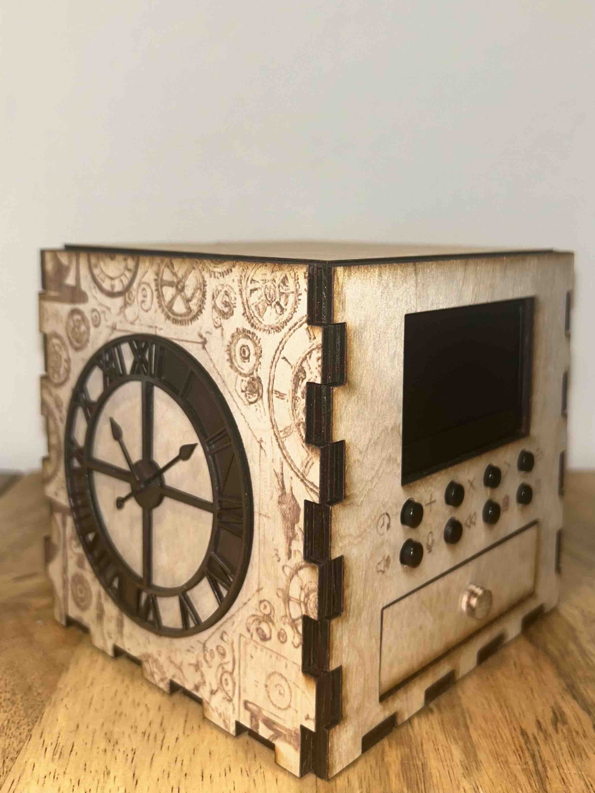
I used a laser cutter to cut it out of 1/4" wood, and all of the components (oled, speaker, on/off, buttons, etc.) fit perfectly into their respective slots/holes. Afterwards, I ended up going back and rastering some designs onto the wood, which I generated using Chat GPT, made black and white, and edited to increase the contrast.
Unfortunately, I made the box prior to finishing the PCB, and quickly realized that in my attempt to make the box small and cute, I'd made a box barely big enough to hold the PCB. But it was the weekend and I couldn't access the laser cutting room, so this project turned into a jigsaw puzzle of trying to fit all the wires inside.
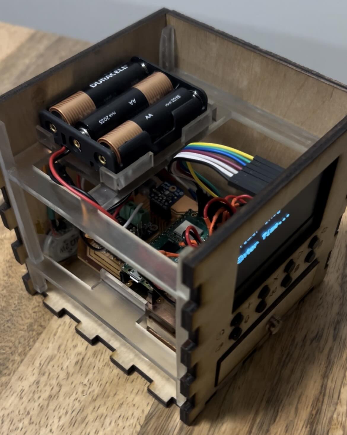
To help with this, I 3D printed an internal structure to hold the PCB and the battery pack (using a Formlabs Resin printer). This made it much more manageable to fit everything inside, keep it neat, and place wires in the right areas.
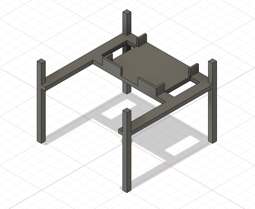
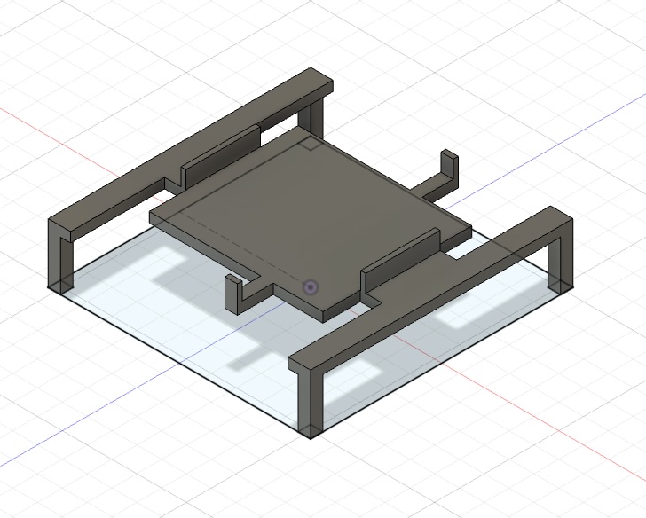
Here are the pieces together!
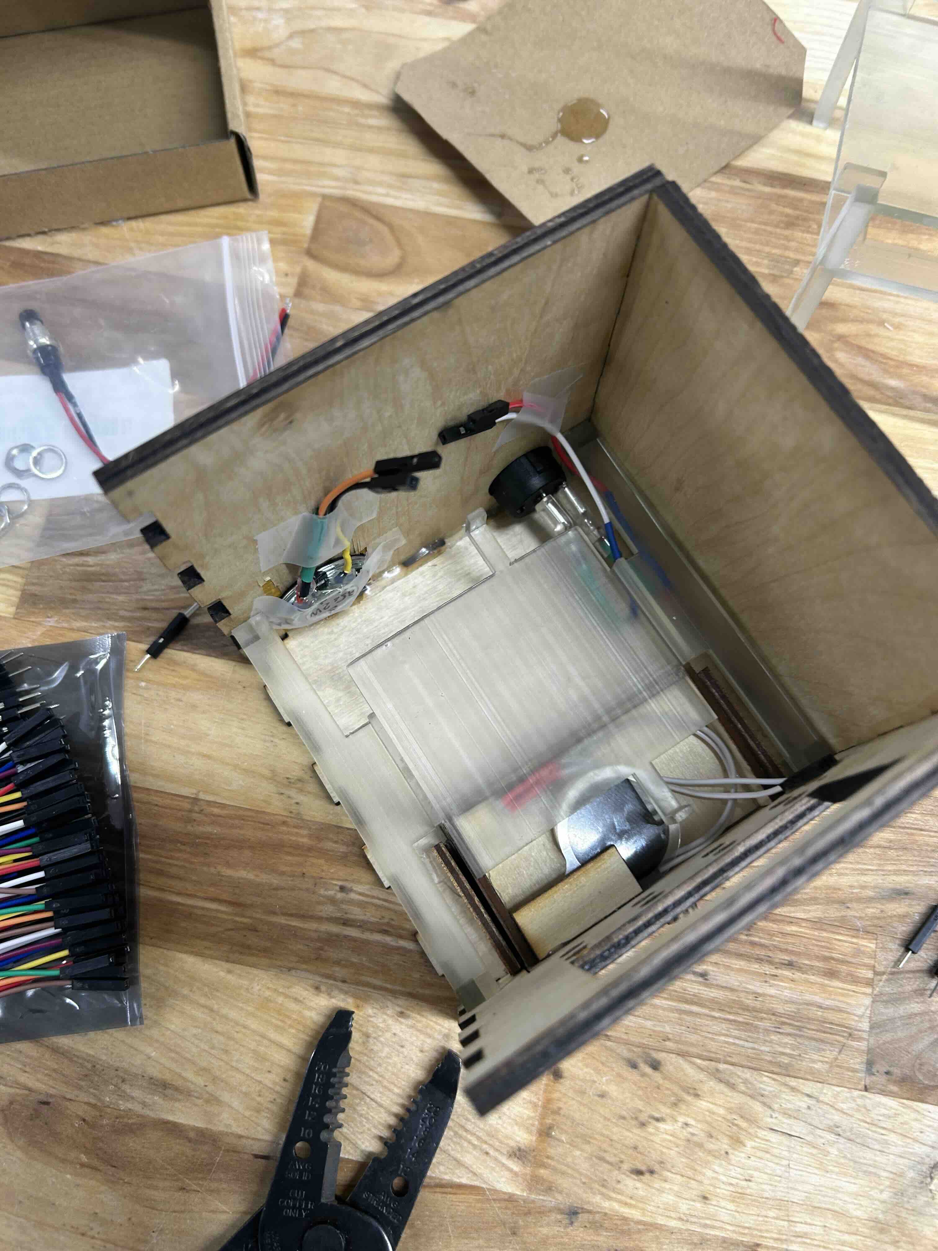
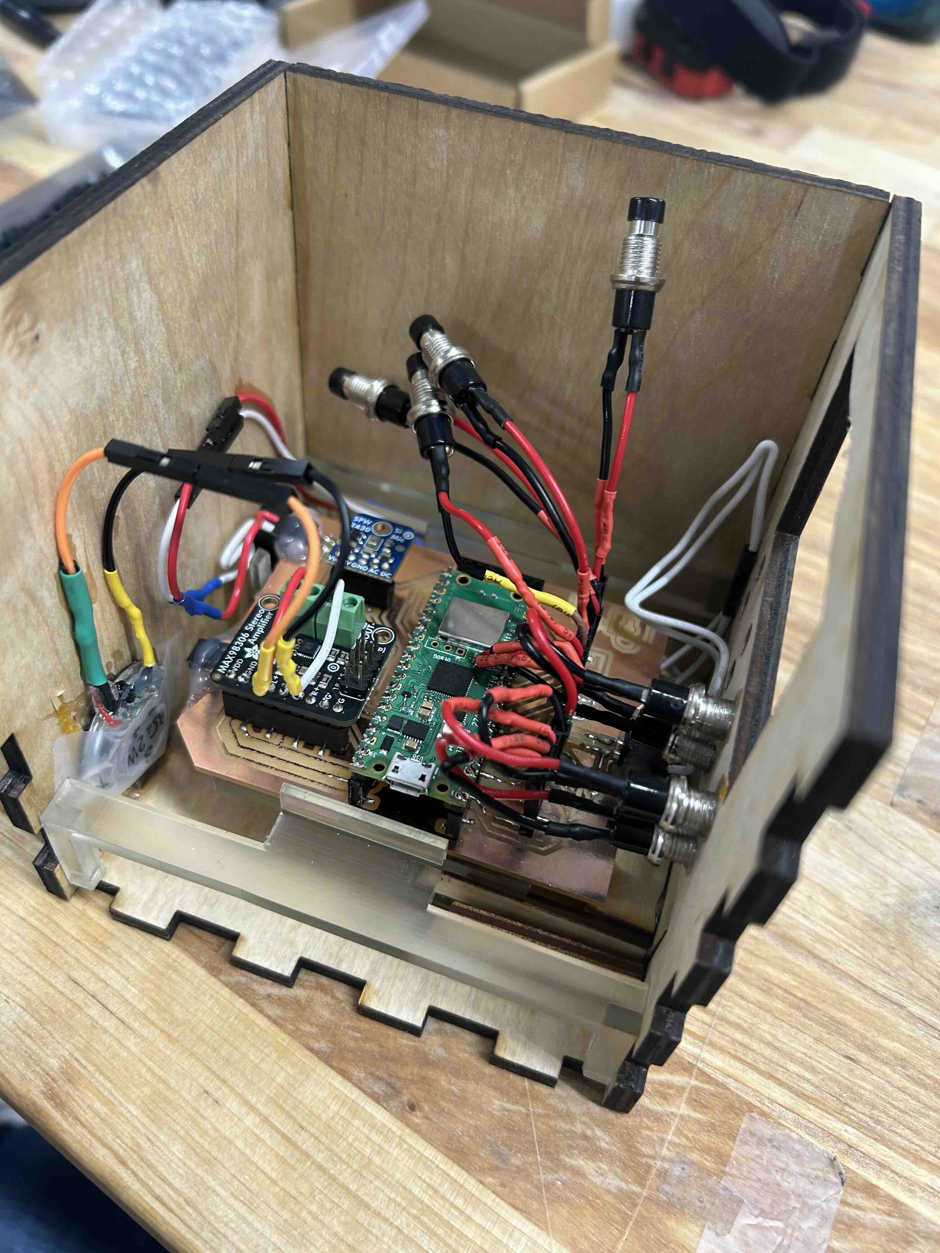
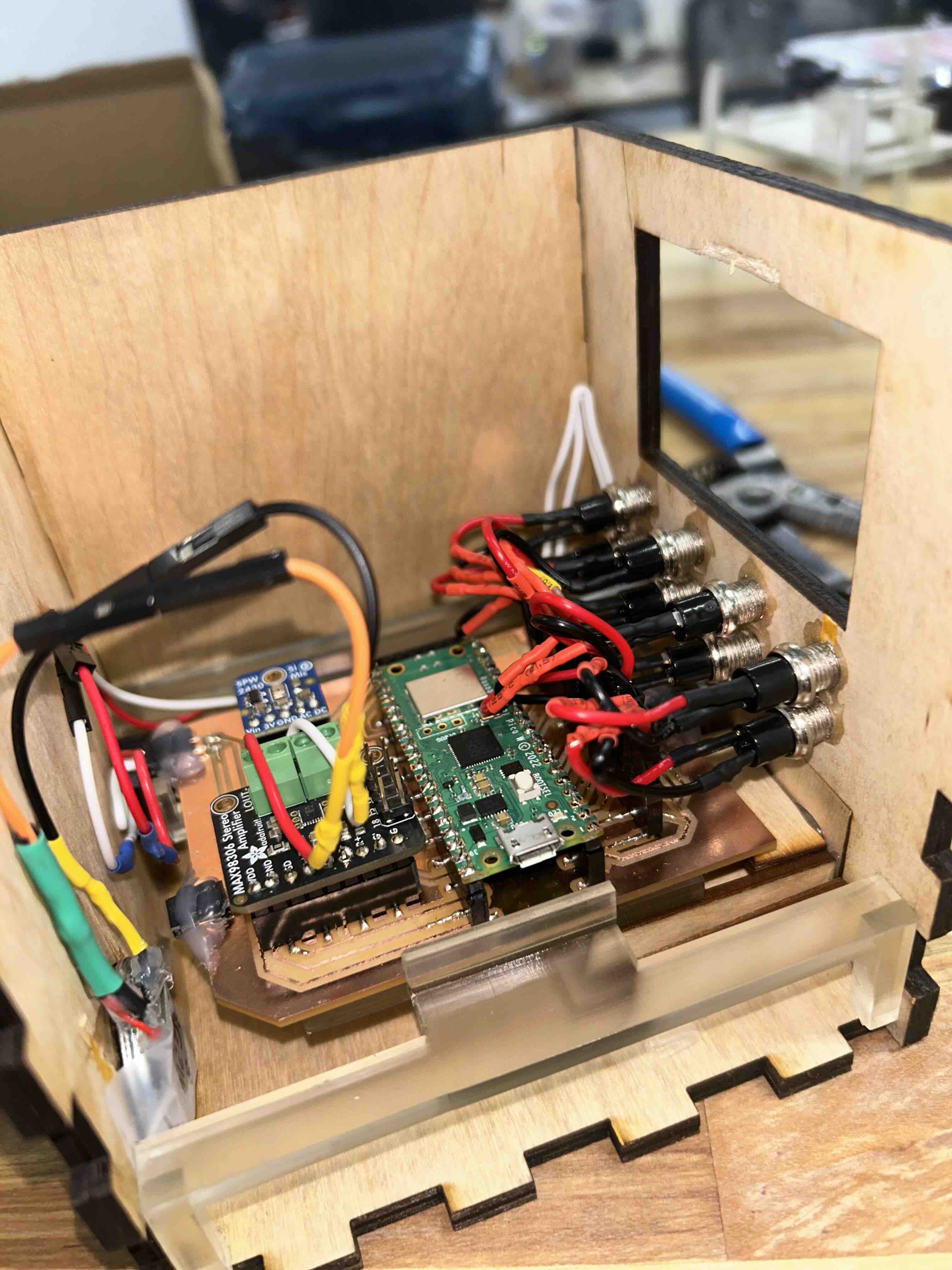
Assembly
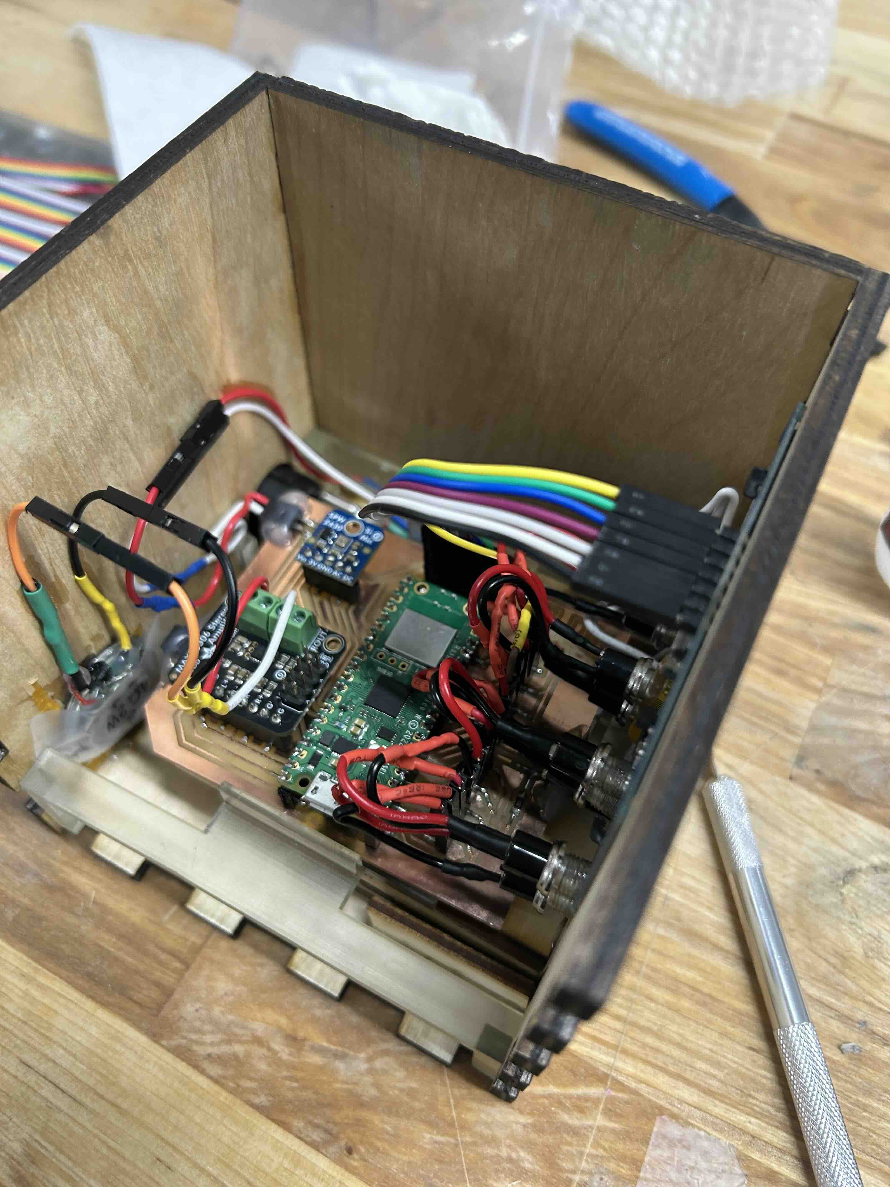
Next I had to put all the components into the box and wire things. Some of the challenges with this were: (1) The box was barely big enough to hold the PCB, making wiring a bit challenging (2) Designing/building the tiny drawer to hold the force sensor--I should have drilled a hole in the back for the wire, instead of sending the wire over the top of the back of the drawer. What I have works, but it could be prettier. (3) A lot of splicing together wires in various configurations, since the components I bought didn't have nice male/female headers on the ends (4) Three of my four speakers breaking (the wires snapping clean off) because I bought cheap Amazon ones (5) The button wires were too short to easily reach the PCB, and getting them to stay put took a lot of super glue.
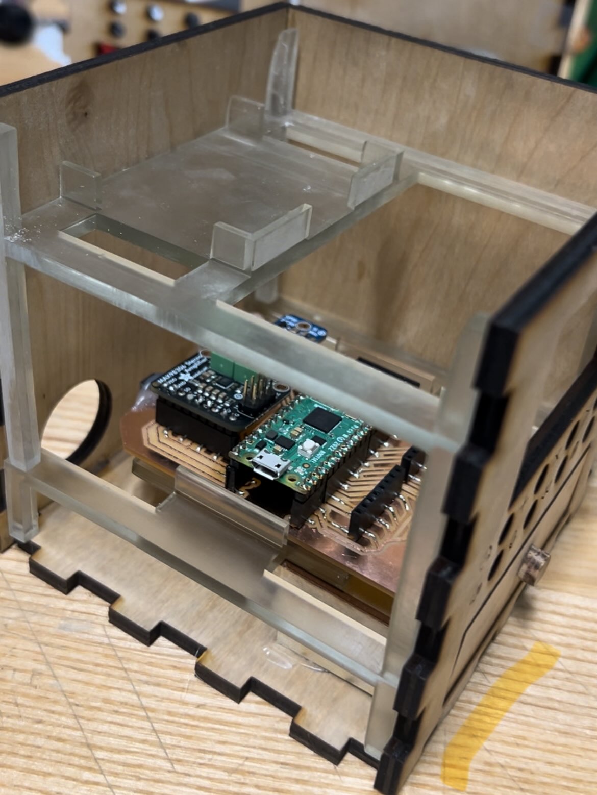
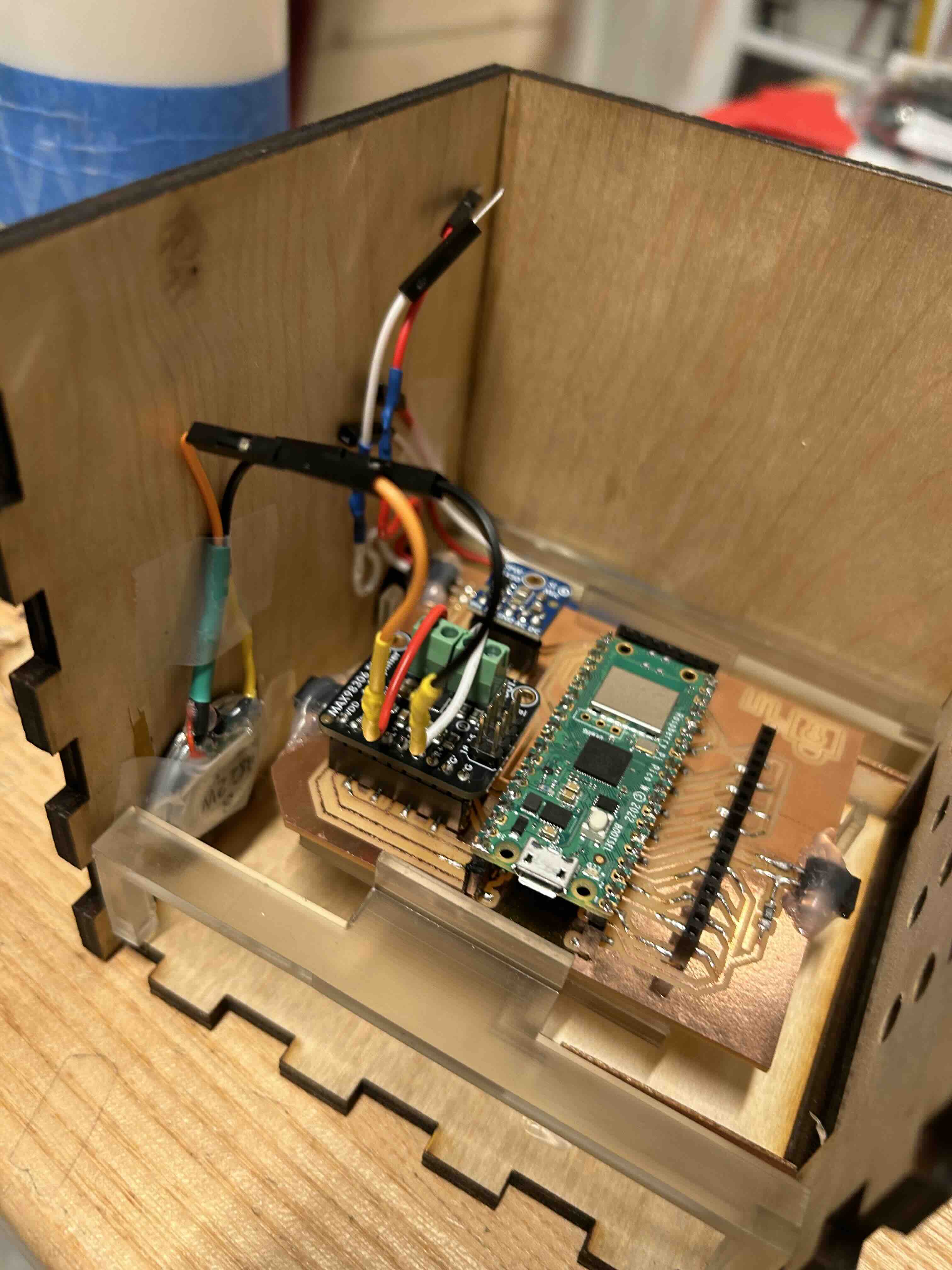
Here are some pictures of the assembly process!
Programming
Finally it was time to program the system! I used the Arduino IDE and got some help from ChatGPT to speed things up. While I was able to read signals from the microphone, I didn't have time to finish coding those related features. I ended up with a system that does the following:
- Allows users to add time to the the Pomodoro timer, clear, start, etc.
- Beeps when the timer goes off
- Switch between two modes: one using the force sensor to detect if you're using your phone, and the other just a normal timer.
- In the 'Strict Focus' mode, if you pick up your phone, the system will continuously beep at you until you put it down.
I have the hardware neccessary to add additional features in the future, which I'll likely do after finals period is over :) I want to add functionality that tracks the cumulative amount of time studied per day/week, uses the microphone to record, and integrate it with an app to access your todo list and display important items for the day. The code is attached below.