Week 10
Computer Controlled Machining
Part 1: Make Something Big
Assignment: make (design+mill+assemble) something big
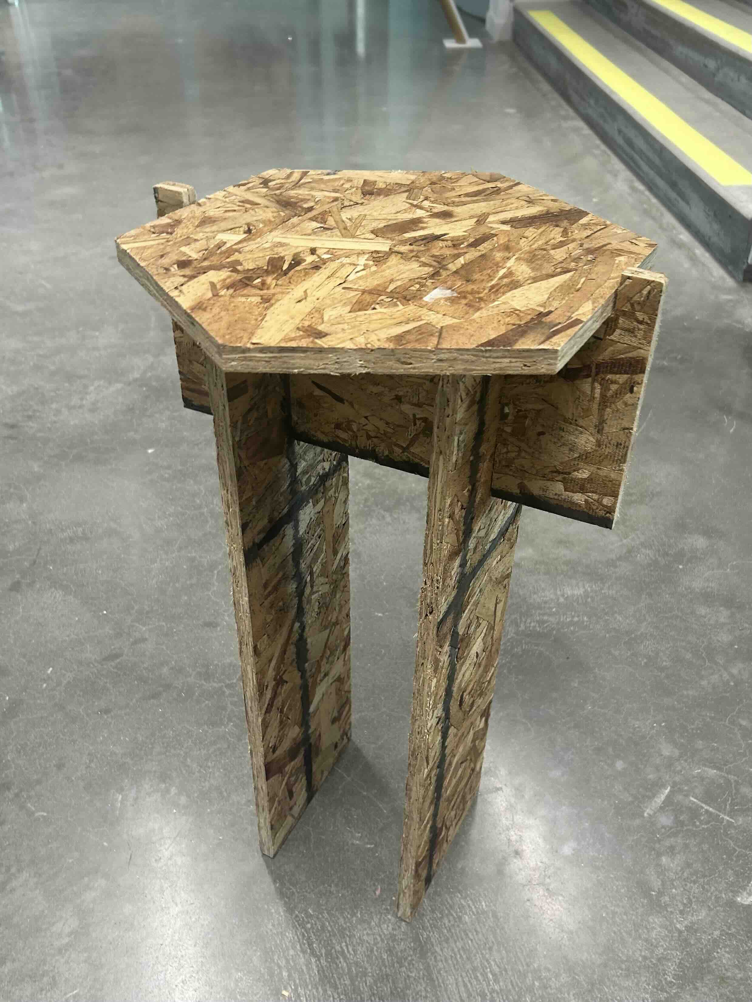
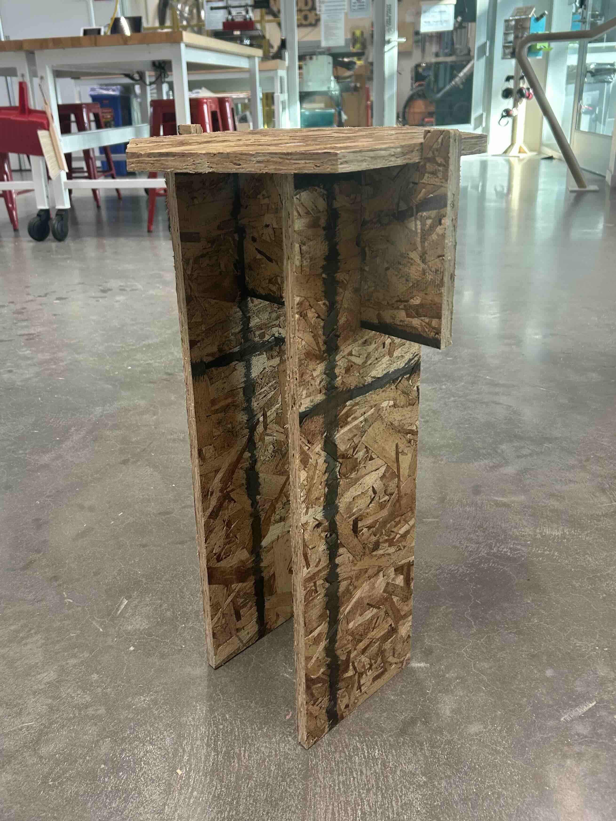
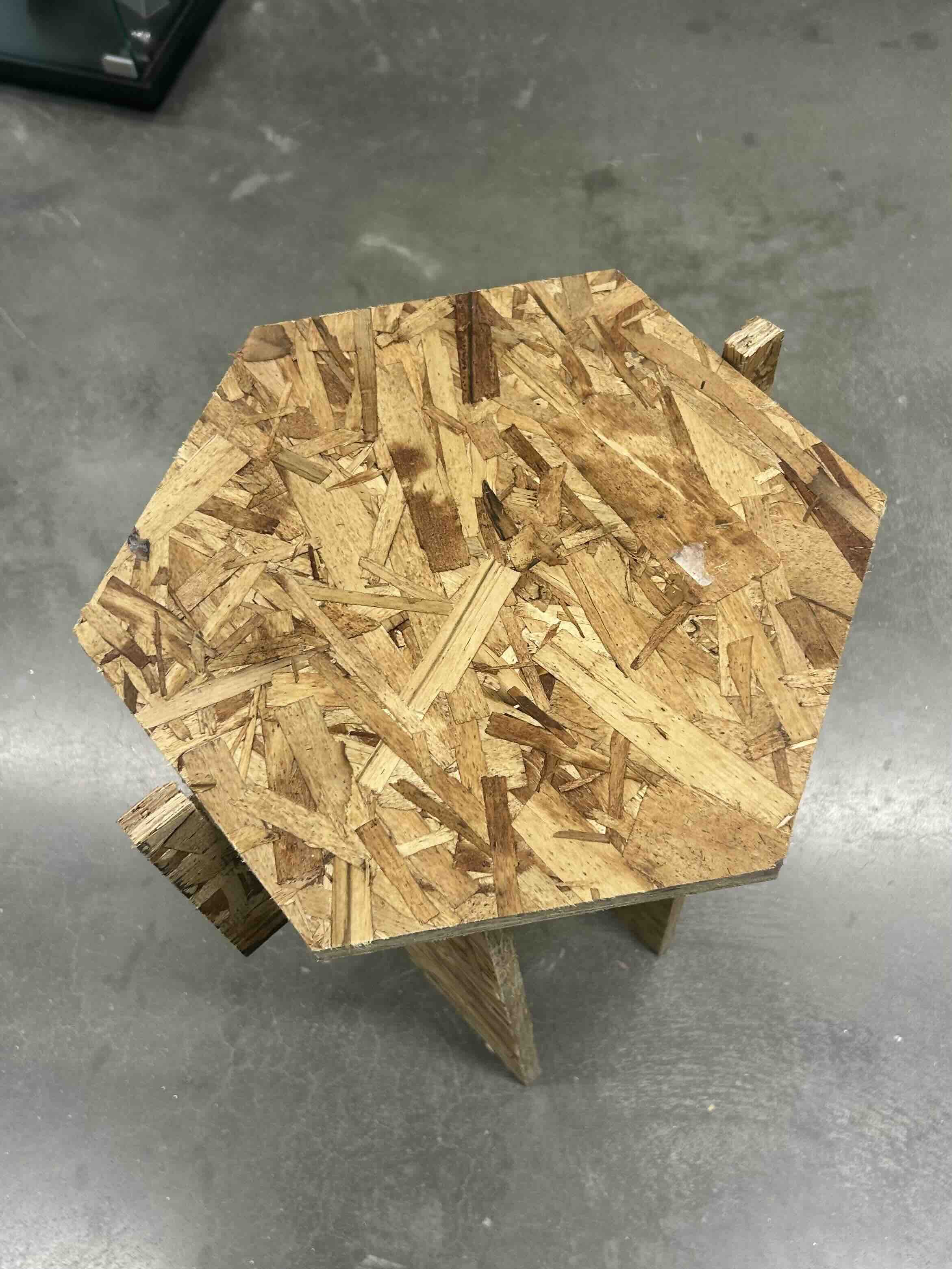
This week we were making something big out of wood--so I decided to build a side table. Disclaimer: It didn't turn out particularly *pretty*
Part 2: CAD Design
I started off with modeling a simple side table in Fusion 360. The general idea was to have a hexagonal top, with two legs connected through a brace. I didn't want to have to use any glue/screws to keep it together, so I built in slots for the pieces to all slide together.
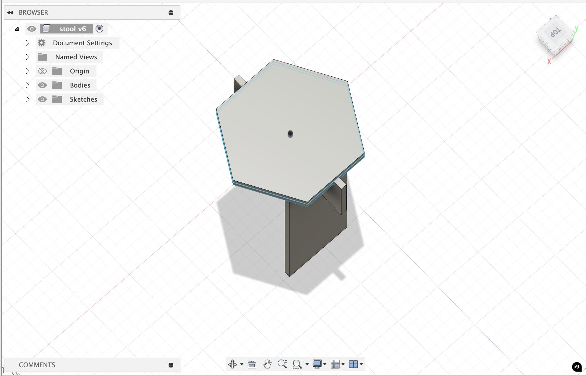
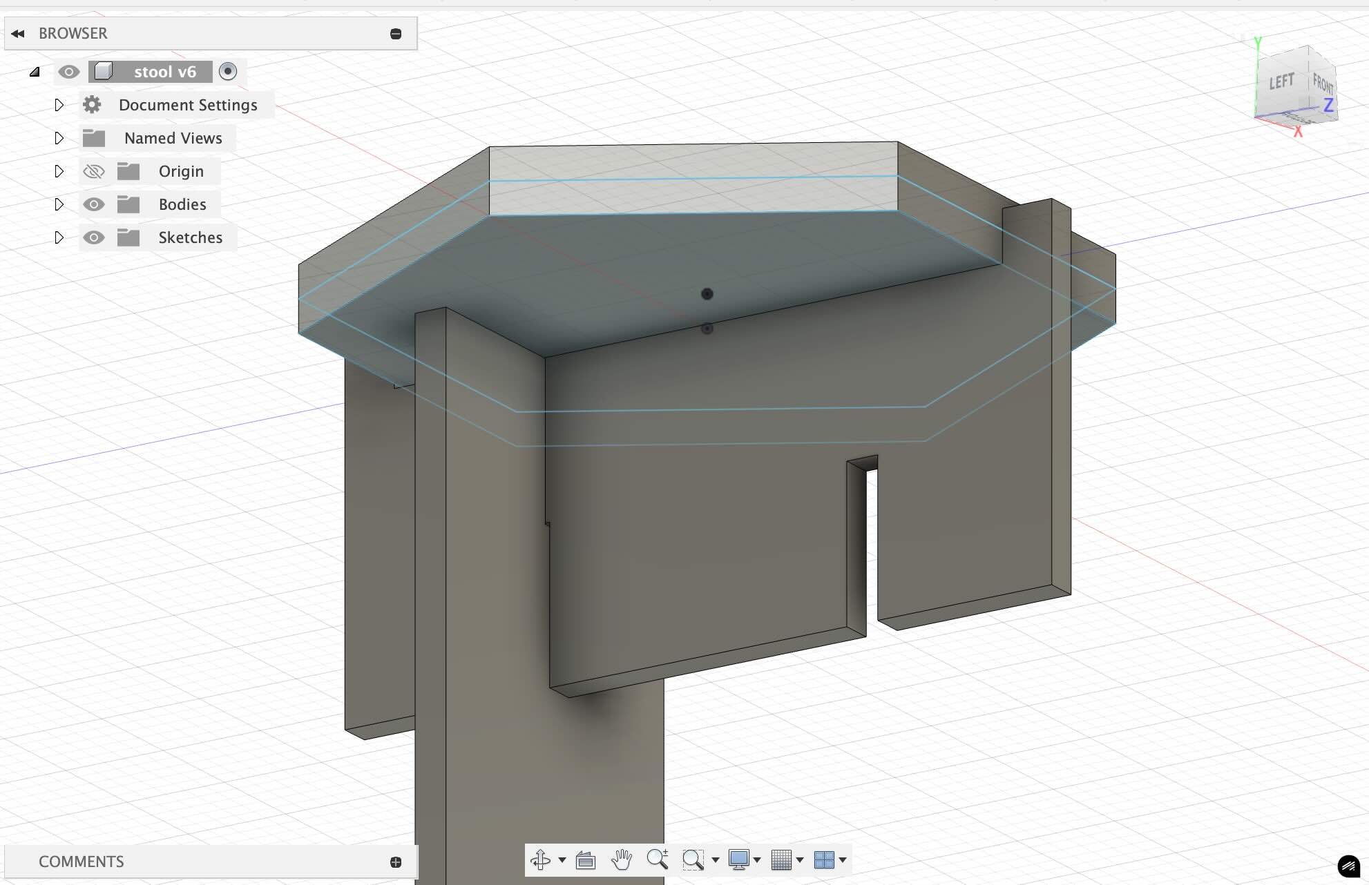
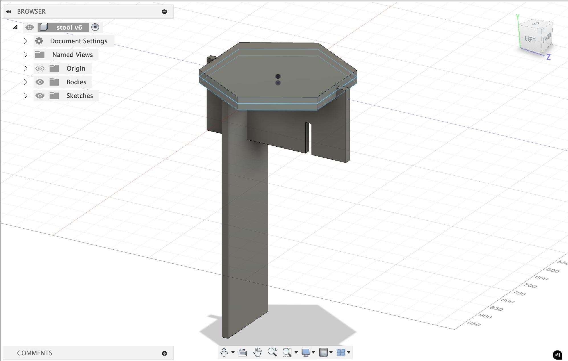
I exported the base sketches as DXF files, which I could then use for the computer controlled cutting.
Part 3: Carbide Create
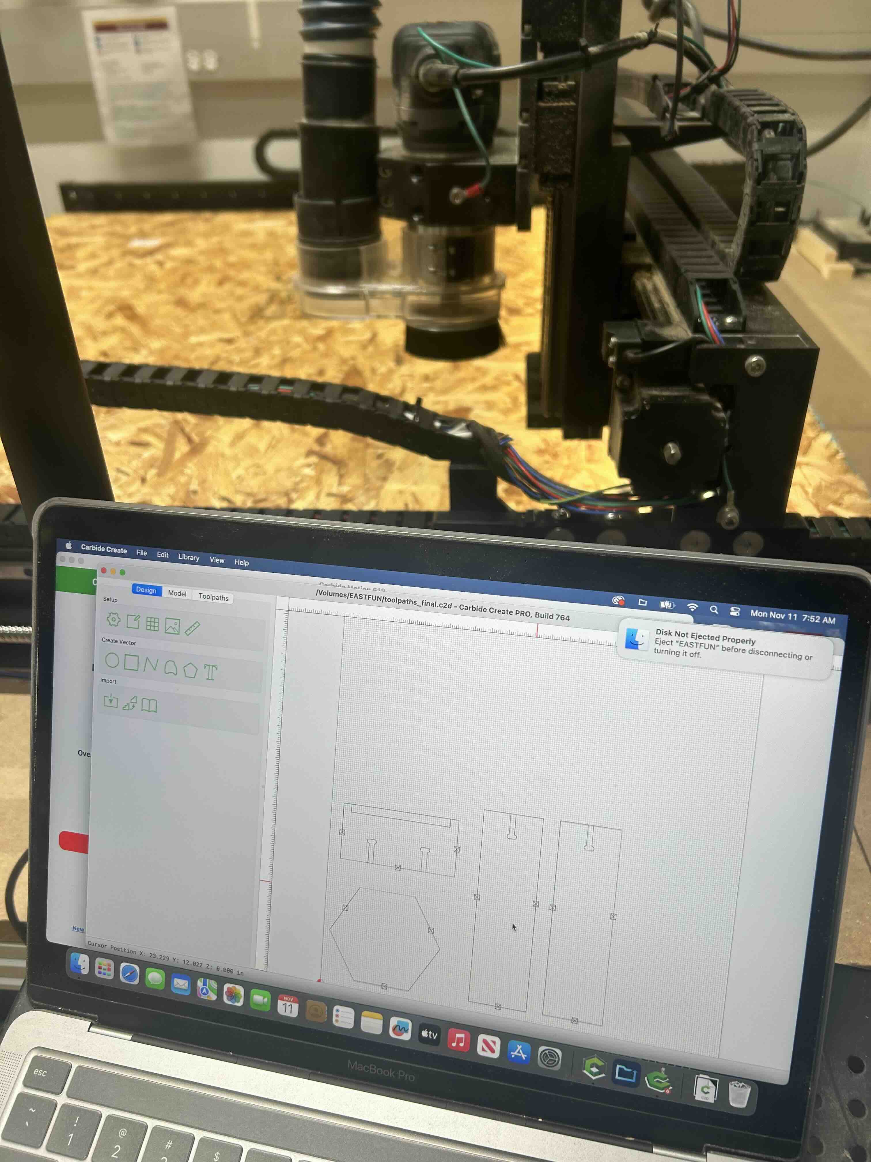
I imported the DXF files into Carbide Create, where I'd be able to set up the toolpaths. Because the machine wouldn't be able to make the small right angles in the slots, I added curves around the corners. I also added 3 tabs on each piece (to keep the pieces from flying out of the machine), which I had to cut off later.
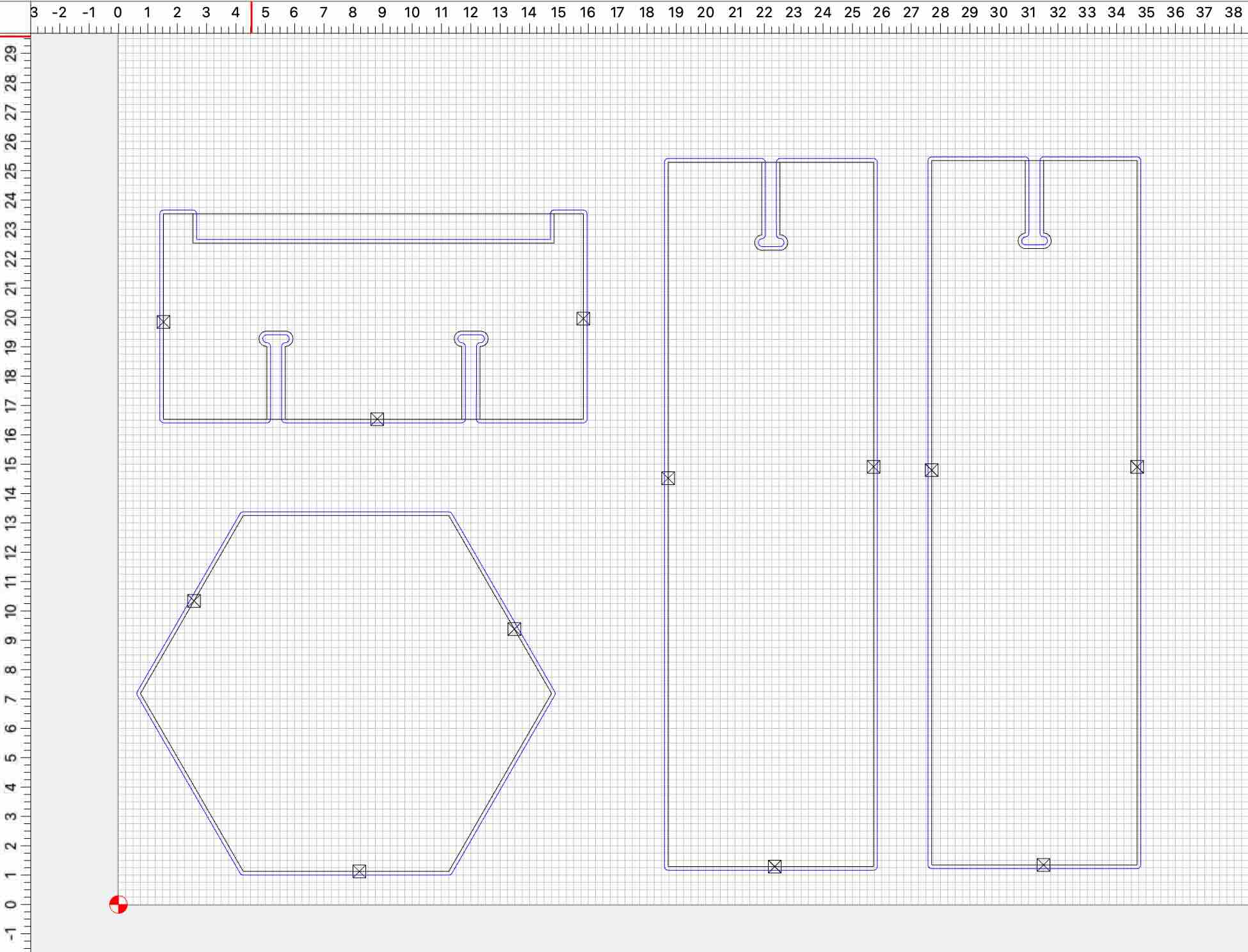
For the toolpath configuration, I used the #201 End Mill (1/4") with a depth per pass of 0.1", a max depth of 0.620", and the offset direction of Outside/Right.
Part 4: Cutting
Next was cutting! I screwed down the board to the bed of the machine to keep it in place, changed out the bit, and zero'd out the machine.
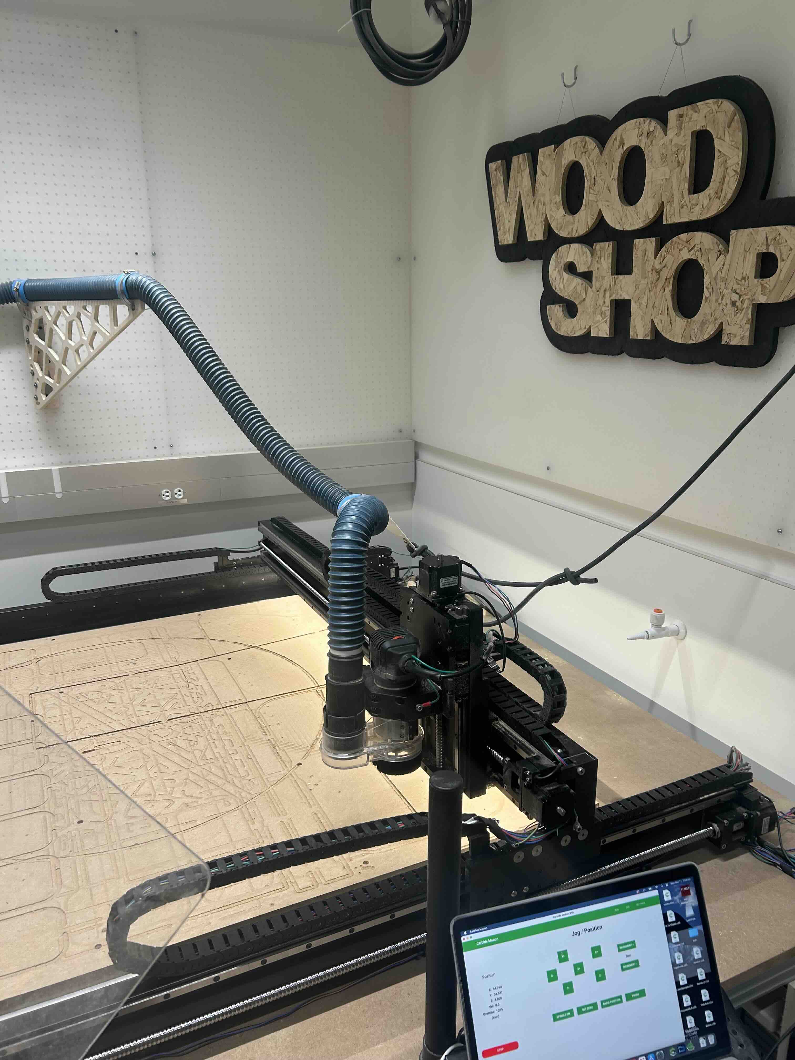
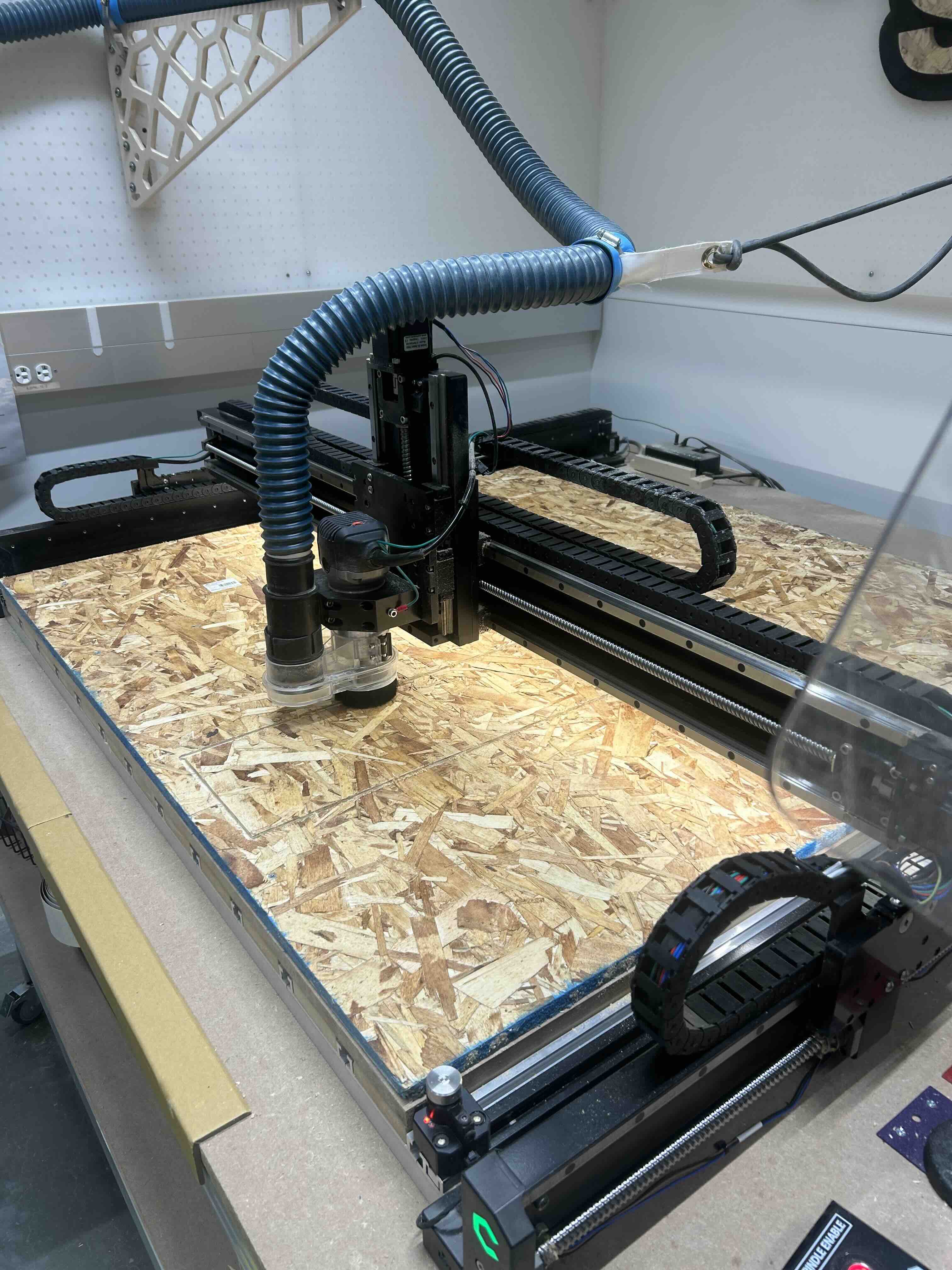
The job took about 30 minutes to complete, leaving me with the pieces cut out (except for the tabs):
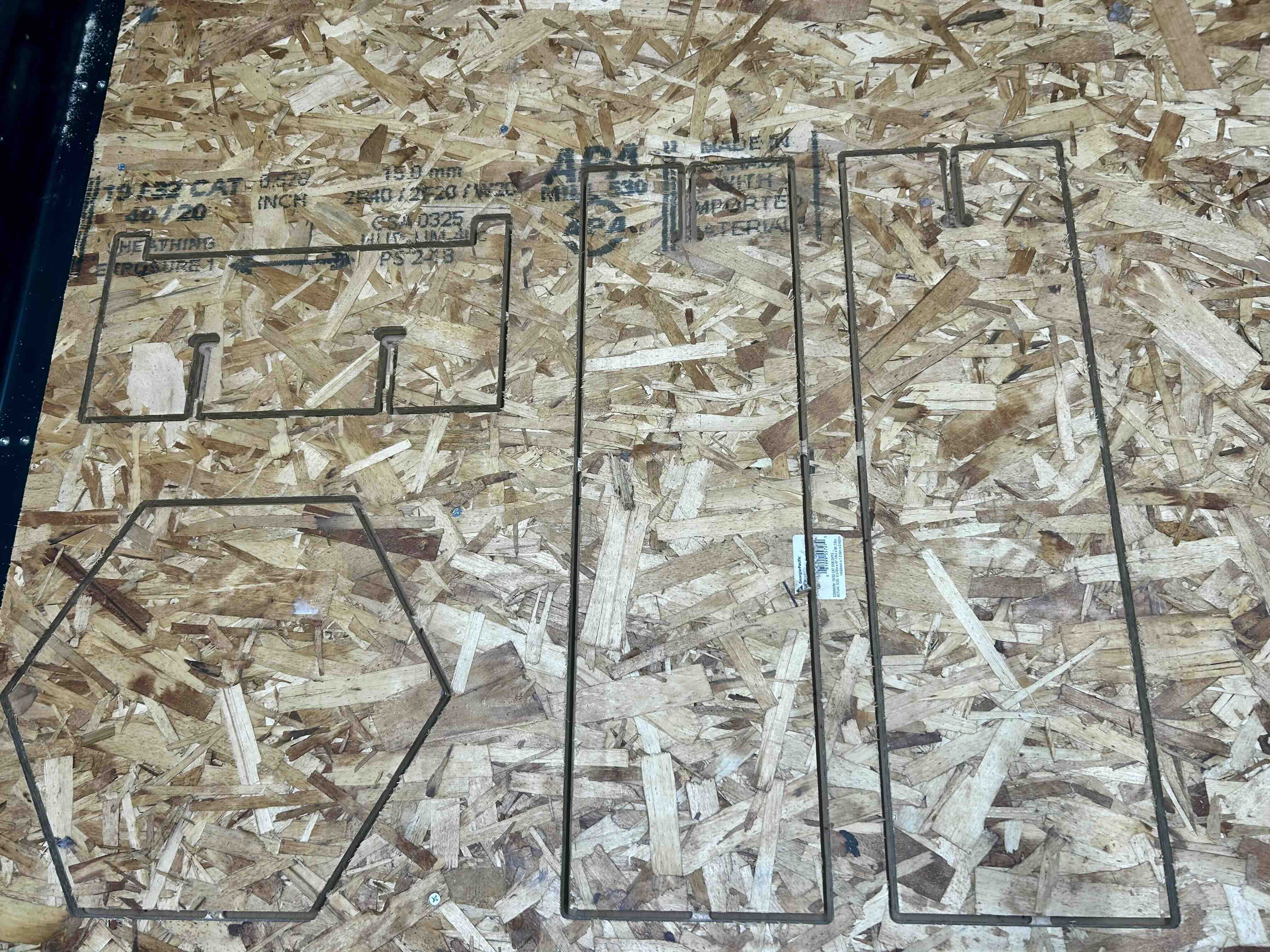
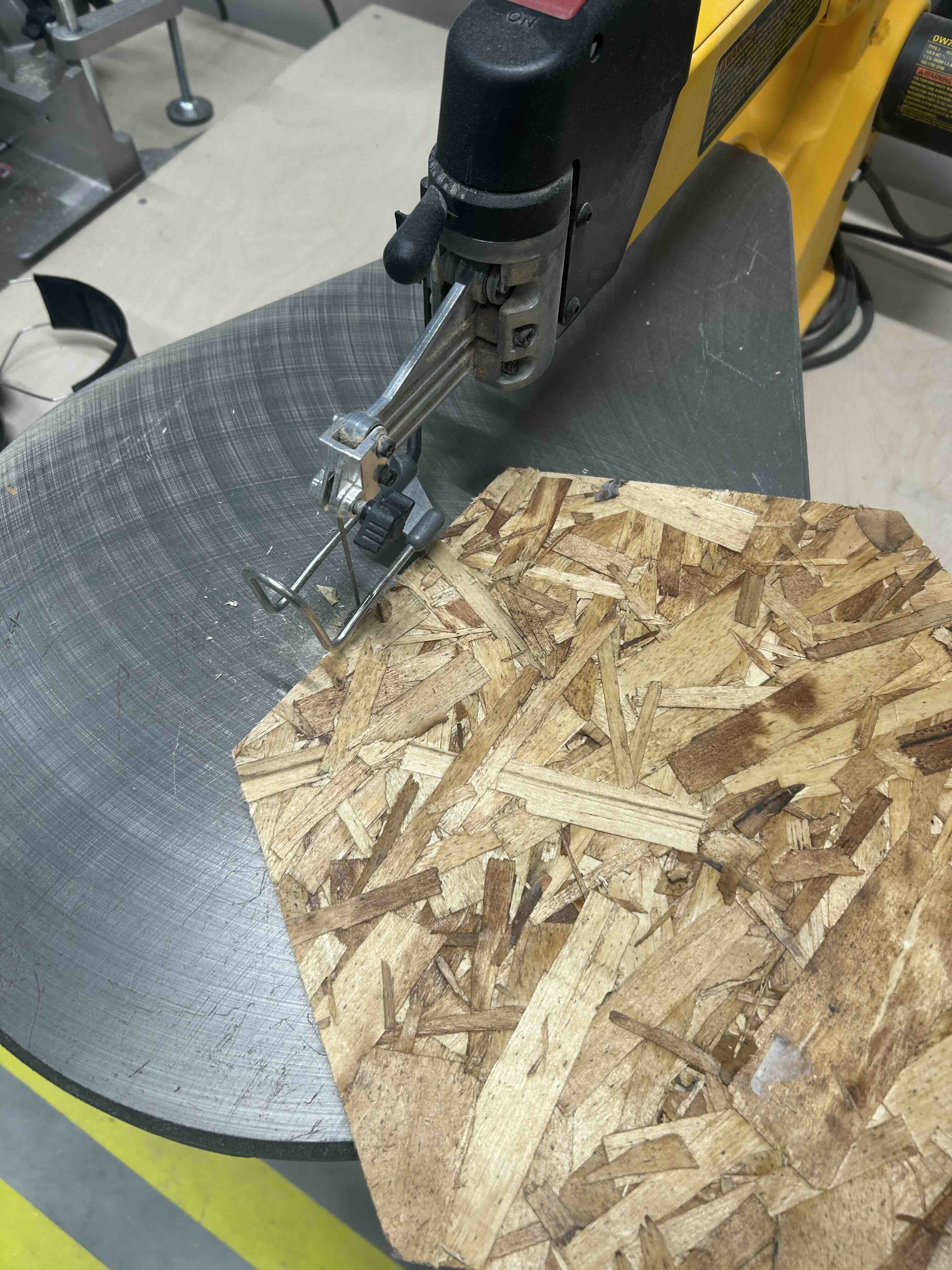
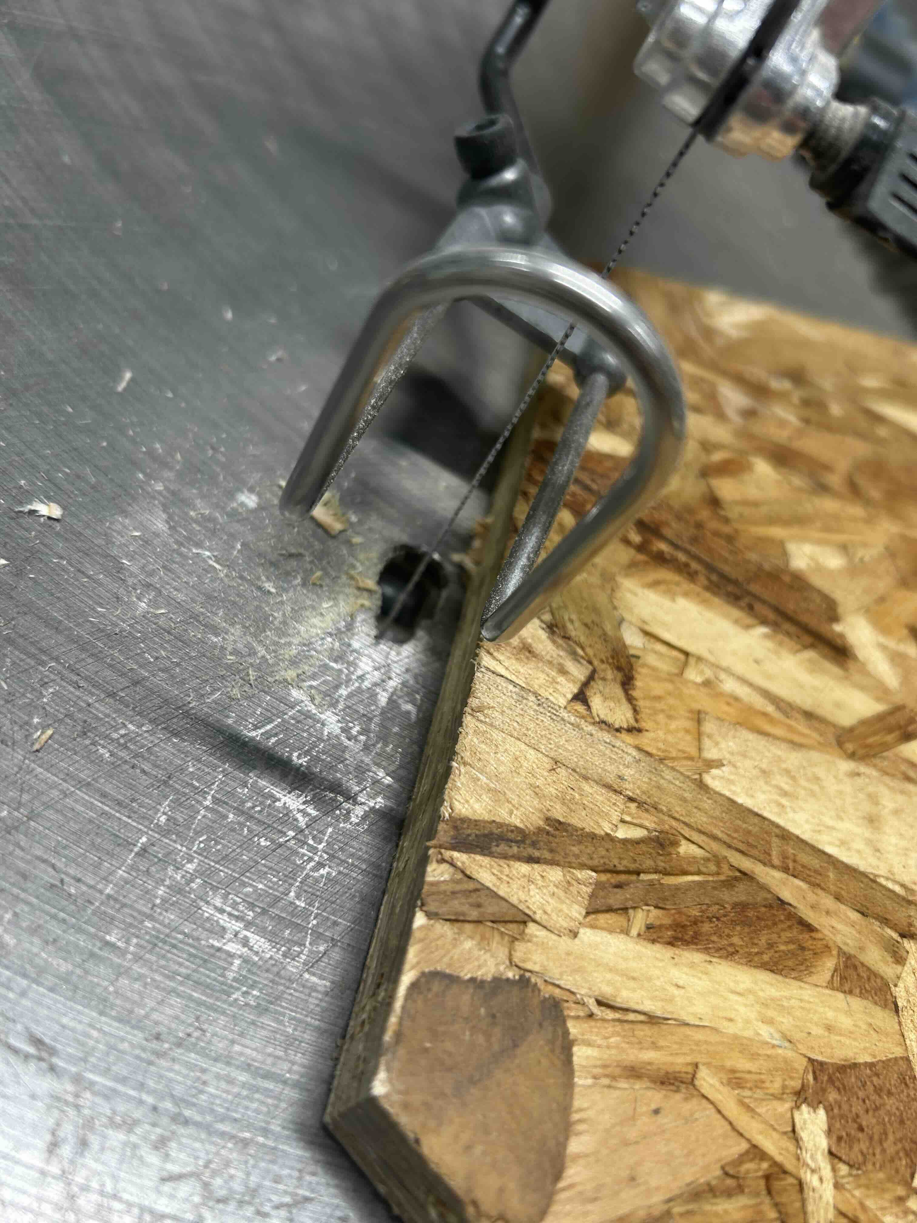
I cut off the tabs with a saw, and then did some cleanup work + sanding to get the pieces ready for assembly:
Part 5: Assembly
Finally, I assembled the pieces together, leaving me with a (slightly Frankenstein-y) side table!
